Table of Contents
Advertisement
Available languages
Available languages
Quick Links
BRUCIATORI A GAS AD UNA FIAMMA PER CALDAIE NORMALI/PRESSURIZZATE
SINGLE-STAGE GAS BURNERS FOR STANDARD AND PRESSURIZED BOILERS
BRULEURS A GAZ A UNE FLAMME POUR CHAUDIERES NORMALES/PRESSURISEES
EINFLAMMIGE GASBRENNER FÜR NORMAL-UND ÜBERDRUCKKESSEL
QUEMADORES DE GAS CON UNA LLAMA PARA CALDERAS NORMALES/PRESURIZADAS
EM 16-E / EM 26-E
MANUALE DI
INSTALLATION AND
NOTICE
INSTALLATIONS-
MANUAL PARA LA
ΕΓΧΕΙΡΙΔΙΟ
INSTALLAZIONE E
MAINTENANCE
D'INSTALLATION
UND
INSTALACIÓN Y EL
ΕΓΚΑΤΑΣΤΑΣΗΣ
MANUTENZIONE
MANUAL
WARTUNGSANLEITUNG
MANTENIMIENTO
ΚΑΙ
ΣΥΝΤΗΡΗΣΗΣ
ET D'ENTRETIEN
Advertisement
Table of Contents

Subscribe to Our Youtube Channel
Related Manuals for Lamborghini Caloreclima EM 26-E


Summary of Contents for Lamborghini Caloreclima EM 26-E
- Page 1 SINGLE-STAGE GAS BURNERS FOR STANDARD AND PRESSURIZED BOILERS BRULEURS A GAZ A UNE FLAMME POUR CHAUDIERES NORMALES/PRESSURISEES EINFLAMMIGE GASBRENNER FÜR NORMAL-UND ÜBERDRUCKKESSEL QUEMADORES DE GAS CON UNA LLAMA PARA CALDERAS NORMALES/PRESURIZADAS EM 16-E / EM 26-E MANUALE DI INSTALLATION AND NOTICE...
- Page 3 ITALIANO Leggere attentamente le istruzioni ed avvertenze contenute sul presente libretto in quanto forniscono importanti indicazioni riguardanti la sicurezza d’installazione, d’uso e di manutenzione. Conservare con cura questo libretto per ogni ulteriore consultazione. L’installazione deve essere effetuata da per- sonale qualificato che sarà responsabile del rispetto delle norme di sicurezza vigenti.
- Page 4 ... per l’ottima scelta. La ringraziamo per la preferenza accordata ai nostri prodotti. LAMBORGHINI CALORECLIMA è un'Azienda quotidianamente impegnata nella ricerca di soluzioni tecniche inno- vative, capaci di soddisfare ogni esigenza. La presenza costante dei nostri prodotti sul mercato italiano ed interna- zionale, è...
-
Page 5: Norme Generali
NORME GENERALI • Il presente libretto costituisce parte integrante ed essenziale del prodotto e dovrà essere consegnato all’installatore. Leggere attentamente le avvertenze contenute nel presente libretto in quanto forniscono importanti indicazioni riguar- danti la sicurezza d’installazione, d’uso e manutenzione. Conservare con cura questo libretto per ogni ulteriore consul- tazione. - Page 6 • Il locale del bruciatore deve essere sempre mantenuto pulito e libero da sostanze volatili, che potrebbero venire aspirate all’interno del ventilatore ed otturare i condotti interni del bruciatore o della testa di combustione. La polvere e estrema- mente dannosa, particolarmente se vi e la possibilità che questa si posi sulle pale del ventilatore, dove andrà a ridurre la ventilazione e produrrà...
-
Page 7: Componenti Principali
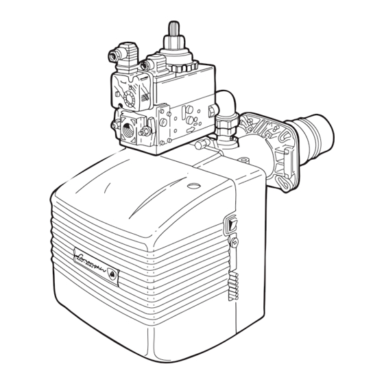
3/4” EM 16-E 3/4” EM 16/L-E 1” EM 26-E * Le dimensioni sono relative al bruciatore con rampa da 20 mbar installata. COMPONENTI PRINCIPALI Legenda 1 Pressostato gas 7 Motore 13 Ventola 2 Valvola di funzionamento 8 Pressostato aria... -
Page 8: Caratteristiche Tecniche
CARATTERISTICHE TECNICHE DESCRIZIONE EM 16-E EM 26-E min. Portata B/P max. min. 12,9 Portata gas Metano max. 16,1 24,6 min. max. Potenza termica min. 68.800 110.940 kcal/h max. 137.600 210.700 kcal/h Motore Trasformatore 10/20 - 15/40 10/20 - 15/4 0... -
Page 9: Curve Pressione/Portata Gas
CURVE PRESSIONE/PORTATA GAS Indicano la pressione del gas in mbar, (nei punti Pi e Pt della rampa gas) necessaria per ottenere una determinata portata in m /h. Le pressioni sono misurate con bruciatore in funzione e si intendono con camera di combustione a 0 mbar. Se la camera è... -
Page 10: Montaggio Alla Caldaia
MONTAGGIO ALLA CALDAIA Fissare la flangia 2 alla caldaia con n° 4 viti 3 interponendo la guarnizione isolante 4 e l’eventuale corda isolante 5. Infilare il bruciatore nella flangia in modo che il boccaglio penetri nella camera di combustione secondo le indicazioni del costruttore della caldaia. -
Page 11: Posizione Elettrodi
In caso contrario perderebbero la loro funzione, compromettendo il funzionamento del bruciatore. È opportuno verificare la corretta posizione dopo ogni intervento sulla testa di combustione. EM 16-E Elettrodo di controllo EM 26-E Elettrodo di controllo - 11... -
Page 12: Collegamenti Elettrici
COLLEGAMENTI ELETTRICI SCHEMA ELETTRICO BRUCIATORE EM 16-E I collegamenti da effettuare a cura dell’installatore sono: - linea di alimentazione - linea termostatica - eventuale lampada di blocco al morsetto S3 - eventuale contaore al morsetto B4 Linea alimentazione 230V-50Hz Legenda Elettrodo di controllo MPE Morsettiera apparecchiatura Termostato di sicurezza... - Page 13 SCHEMA ELETTRICO BRUCIATORE EM 26-E I collegamenti da effettuare a cura dell’installatore sono: - linea di alimentazione - linea termostatica - eventuale lampada di blocco al morsetto S3 - eventuale contaore al morsetto B4 Linea alimentazione 230V-50Hz Legenda Elettrodo di controllo...
-
Page 14: Ciclo Di Funzionamento
CICLO DI FUNZIONAMENTO Inizia alla chiusura della linea termostatica e del PG. Il PA deve essere in posizione di riposo. È il tempo di attesa e di autoverifica e dura 2,5 sec. Inizia con l’avviamento del motore e con la fase di preventilazione: dura 5 sec., entro i quali il pressostato aria PA deve dare il consenso. -
Page 15: Allacciamento Gas
In caso di blocco bruciatore nel pulsante di blocco sarà fissa la luce rossa. Premendo il pulsante trasparente si procede allo sblocco del dispositivo di comando e controllo. Premendo per più di 3 sec. la fase di diagnosi verrà attivata (luce rossa con lampeggio rapido), nella tabella sottostante viene riportato il significato della causa di blocco o malfunzionamento in funzione del numero di lampeggi (sempre di colore rosso). -
Page 16: Regolazione Aria Di Combustione
La sua regolazione avviene tramite la vite A, in base alle indicazioni segnalate dall’indice. Indice di riferimento REGOLAZIONE TESTA DI COMBUSTIONE EM 26-E - Allentare i pomelli B. - Agendo su di essi si modifica la posizione del boccaglio rispetto alla testa di combustione. - Page 17 REGOLAZIONE VALVOLA MULTIBLOC MB-DLE.../B01 1 Regolazione velocità d’apertura 2 Regolazione portata 3 Regolazione stabilizzatore 4 Vite di bloccaggio Dopo aver allentato la vite 4, ruotare la ghiera 2 in senso orario per una portata minima, in senso antiorario per una portata massima.
- Page 18 0,4 - 3 GW 150 A2 5 - 150 GW 150 A5 5 - 120 EM 26-E LGW 3 AP 0,4 - 3 CONTROLLO CORRENTE DI IONIZZAZIONE APPARECCHIATURA Deve essere rispettato il valore minimo di 3 A e non presentare forti oscillazioni.
-
Page 19: Funzionamento Con Diversi Tipi Di Gas
CONTROLLO COMBUSTIONE Al fine di ottenere i migliori rendimenti di combustione e nel rispetto dell’ambiente, si raccomanda di effettuare con gli adeguati strumenti, controllo e regolazione della combustione. Valori fondamentali da considerare sono: . Indica con quale eccesso d’aria si svolge la combustione. Se si aumenta l’aria il valore di CO % diminuisce, se si diminuisce l’aria di combustione il CO aumenta. - Page 20 EM 26-E Togliere gli elettrodi G dal gruppo testa. Allentare le viti H e sostituire il gruppo testa I. Montare gli elettrodi attenendosi alle misure riportate nel manuale. PORTATA GAS Per quanto riguarda la portata del gas, mancando in genere la possibilità di controllo diretto (contatore), si può empirica- mente procedere attraverso i valori della temperatura fumi della caldaia.
-
Page 21: Manutenzione
- Agganciare la piastra portacomponenti nella posizione di servizio 5 ed eseguire la manutenzione alla testa di combustione (fig.3). EM 26-E Per accedere ai componenti principali è sufficiente togliere il cofano (fig.4). La manutenzione alla testa di combustione si esegue nel seguen- te modo: - Svitare le viti 1 e togliere il cofano 2 (fig.4). -
Page 22: Irregolarità Di Funzionamento
IRREGOLARITÀ DI FUNZIONAMENTO DIFETTO CAUSA RIMEDIO 1 IL BRUCIATORE NON SIA AV- A. Mancanza di energia elettrica. A. Controllare i fusibili della linea di VIA. B. Non arriva gas al bruciatore. alimentazione. Controllare il fusi- bile dell’apparecchiatura elettrica. Controllare la linea dei termostati e del pressostato del gas. - Page 23 - 23...
- Page 24 ... on your excellent choice. Thank you for choosing our products. LAMBORGHINI CALORECLIMA is daily committed to seeking innovative technical solutions to satisfy every need. Constant presence of our products on the Italian and international markets is assured by a widespread network of Agents and Dealers assisted by “LAMBORGHINI SERVICE”...
-
Page 25: General Instructions
GENERAL INSTRUCTIONS • This booklet constitutes an integral and essential part of the product and should be supplied to the installer. Read the instructions contained in this booklet carefully as they give important directions regarding the safety of installation, use and maintenance. - Page 26 • The room where the burner is housed should be kept clean at all times, and there should be no volatile substances in the vicinity, substances which could be sucked into the fan and could block up the internal ducts of the burner or combustion head.
-
Page 27: Dimensions (Mm)
EM 16-E 3/4” 3/4” EM 16/L-E EM 26-E 1” * The dimensions refer to a burner with a 20 mbar gas train fitted. MAIN COMPONENTS Legend 1 Gas pressure switch 7 Motor 13 Fan 2 Operation valve... -
Page 28: Technical Features
TECHNICAL FEATURES DESCRIPTION EM 16-E EM 26-E min. B/P delivery max. min. 12,9 Methane delivery max. 16,1 24,6 min. max. Thermal output min. 68.800 110.940 kcal/h max. 137.600 210.700 kcal/h Motor Transformer kV/mA 10/20 - 15/40 10/20 - 15/40 Total absorbed power... -
Page 29: Pressure Curves/Gas Delivery
PRESSURE CURVES/GAS DELIVERY These curves show the gas pressure, in millibars, (at points Pi and Pt along the gas train) necessary to produce a given delivery in m /h. The pressures have been measured with the burner working and with a pressure of 0 mbar in the com- bustion chamber. - Page 30 ASSEMBLY ONTO THE BOILER Fix flange 2 to the boiler using 4 screws 3 interposing the insulation gasket 4 and the possible insulating cord 5. Insert the burner in the flange so that the draught tube penetrates into the combustion chamber by the length suggested by the boiler manufacturer.
-
Page 31: Electrodes Adjustment
If this were to happen they would no longer work, thus impairing operation of the burner itself. The position of the electrodes should always be checked after any work on the combustion head. EM 16-E Control electrode EM 26-E Control electrode - 31... -
Page 32: Wiring Diagrams
WIRING DIAGRAMS WIRING DIAGRAM - EM 16-E BURNER The connections to be carried out by the installer are: - Main supply line - Thermostatic line - Lock-out lamp at terminal S3 (if present) - Hour counter at terminal B4 (if present) Mains supply 230V-50Hz Legend... - Page 33 WIRING DIAGRAM - EM 26-E BURNER The connections to be carried out by the installer are: - Main supply line - Thermostatic line - Lock-out lamp at terminal S3 (if present) - Hour counter at terminal B4 (if present) Mains supply...
-
Page 34: Operating Cycle
OPERATING CYCLE Begins with the closure of the thermostatic line or the PG. The PA must be in the rest position. This is the waiting and self-test time lasting for 2,5 seconds. Begins when the motor starts up and with the pre-purge phase;... -
Page 35: Gas Connection
If the burner is locked out, there will be a steady red light on the lock out pushbutton. By pressing the transparent pushbutton, the control and checking device will be released. By pressing it for more than 3 seconds, the diagnosis stage will be activated (red light flashes rapidly). The table below describes the causes of the lock out or fault in relation to the number of flashes (always red). -
Page 36: Combustion Air Adjustment
Adjust the combustion head by acting on the screw A according to the indications shown on the index. Reference index COMBUSTION HEAD ADJUSTMENT EM 26-E - Loosen the knobs B. - Acting on these modifies the position of the draught tube with respect to the combustion head. - Page 37 VALVE ADJUSTMENT MULTIBLOC MB-DLE.../B01 1 Opening speed adjustment 2 Delivery adjustment 3 Stabilizer adjustment 4 Locking screw After loosening screw 4, turn the locknut 2 clockwise to obtain minimum delivery, anticlockwise for maximum delivery. Once adjustment is completed block screw 4 again. CHECKING THE QUANTITY OF GAS AT IGNITION To check the quantity of gas at ignition, apply the following formula: Ts x Qs...
- Page 38 0,4 - 3 GW 150 A2 5 - 150 GW 150 A5 5 - 120 EM 26-E LGW 3 AP 0,4 - 3 CHECKING CONTROL BOX IONIZATION CURRENT The minimum value of 3 A should be observed, and large oscillations are to be avoided.
-
Page 39: Operation With Different Types Of Gas
CHECKING COMBUSTION In order to obtain optimum combustion efficiency and to safeguard the environment, we recommend to check, and regulate combustion using the appropriate instruments. The most important levels to be checked are: . The level of CO indicates the excess of air during combustion. If the quantity of air is increased, then the CO level decreases, while a decrease in combustion air leads to an increase in CO . - Page 40 EM 26-E Remove the electrodes G from the head assembly. Loosen the screws H and replace the head assembly I. Fit the electro- des as per the instructions given in the manual. GAS DELIVERY Per quanto riguarda la portata del gas, mancando in genere la possibilità di controllo diretto (contatore), si può empirica- mente procedere attraverso i valori della temperatura fumi della caldaia.
-
Page 41: Maintenance
- Unscrew the screws 3 and the central pin 4 (fig.2). - Hang the component holder plate into the service position 5 and effect combustion head maintenance (fig.3). EM 26-E To gain access to the main components, remove the cover (fig.4). Combustion head maintenance should be made as follows: - Unscrew the screws 1 and remove the cover 2 (fig.4). -
Page 42: Fault-Finding Chart
FAULT-FINDING CHART FAULT CAUSE REMEDY 1 T H E B U R N E R D O E S N O T A. No electricity. A. Check the main fuses. START. B. Gas fails to reach the burner. Check the control box fuse. Check thermostats line and gas pressure switch. - Page 43 - 43...
- Page 44 ... pour votre choix d’excellence! Nous vous remercions pour avoir choisi nos produits. LAMBORGHINI CALORECLIMA s’active quotidiennement dans la recherche de solutions techniques innovantes et performantes. Les Agents et Concessionnaires de notre réseau assurent leur présence constante et la diffusion de nos produits sur le marché...
-
Page 45: Normes Generales
NORMES GENERALES • Ce livret est partie intégrante et essentielle du produit et il doit être remis à l’installateur. Lire attentivement les conseils conte- nus dans le présent livret car ils fournissent des indications importantes sur la sécurité d’installation, l’utilisation et l’entretien. Bien conserver ce livret pour toute consultation ultérieure. - Page 46 • La pièce du brûleur doit toujours être propre et ne doit absolument pas contenir de substances volatiles, qui pourraient être aspirées à l’intérieur du ventilateur et obstruer les conduits internes du brûleur ou de la tête de combustion. La poussière est extrêmement nuisible, en particulier lorsqu’elle se dépose sur les pales du ventilateur, réduisant la ven- tilation et donnant lieu à...
-
Page 47: Composants Principaux
3/4” EM 16-E EM 16/L-E 3/4” EM 26-E 1” * Les dimensions sont en proportion avec le brûleur équipé de rampe de 20 mbars. COMPOSANTS PRINCIPAUX Légende 1 Pressostat du gaz 7 Moteur 13 Ventilateur 2 Vanne de fonctionnement 8 Pressostat de l’air... -
Page 48: Caracteristiques Tecniques
CARACTERISTIQUES TECNIQUES DESCRIPTION EM 16-E EM 26-E min. Débit B/P max. min. 12,9 Débit Méthane max. 16,1 24,6 min. max. Puissance thermique min. 68.800 110.940. kcal/h max. 137.600 210.700 kcal/h Moteur Transformateur kV/mA 10/20 - 15/40 10/20 - 15/40 Puissance totale absorbée Pression Méthane... -
Page 49: Courbes De Pression/Debit Du Gaz
COURBES DE PRESSION/DEBIT DU GAZ Elles indiquent la pression du gaz en mbars (aux points Pi et Pt de la rampe de gaz) nécessaire pour obtenir un débit donné en m /h. Les pressions sont mesurées avec le brûleur en marche, lorsque la chambre de combustion est à 0 mbar. Si la chambre est en pression, la pression de gaz nécessaire s’obtient en ajoutant la valeur de la pression de la chambre à... -
Page 50: Installation Sur La Chaudiere
INSTALLATION SUR LA CHAUDIERE Fixer la bride 2 à la chaudière à l’aide des 4 vis 3 en interposant le joint isolant 4 et éventuellement la bande isolante 5. Enfiler le brûleur dans la bride de manière à ce que l’embout pénètre dans la chambre de combustion selon les indications du fabricant de la chaudière. -
Page 51: Position Des Electrodes
Il convient de vérifier la bonne position des électrodes après toute intervention effectuée sur la tête de combustion. EM 16-E Electrode de contrôle EM 26-E Electrode de contrôle - 51... -
Page 52: Connexions Electriques
CONNEXIONS ELECTRIQUES SCHEMA ELECTRIQUE BRULEUR EM 16-E L’installateur devra effectuer les connexions suivantes: - la ligne d’alimentation. - la ligne thermostatique. - la lampe témoin d’arrêt éventuelle à la borne S3. - le compteur éventuel à la borne B4. Ligne d’alimentation 230V-50Hz Légende Electrode de contrôle... - Page 53 SCHEMA ELECTRIQUE BRULEUR EM 26-E L’installateur devra effectuer les connexions suivantes: - la ligne d’alimentation. - la ligne thermostatique. - la lampe témoin d’arrêt éventuelle à la borne S3. - le compteur éventuel à la borne B4. Ligne d’alimentation 230V-50Hz Légende...
-
Page 54: Cycle De Fonctionnement
CYCLE DE FONCTIONNEMENT Commence à la fermeture de la ligne ther- mostatique et du PG. PA doit être dans la position de repos. C’est le temps d’attente et d’autocontrôle, d’une durée de 2,5 secondes. Commence au moment du démarrage du moteur et avec la phase de préventilation: durée 5 secondes. -
Page 55: Branchement Du Gaz
En cas de mise en sécurité du brûleur, la lumière rouge du bouton de mise en sécurité sera fixe. En enfonçant le bouton transparent, on débloque le dispositif de commande et de contrôle. Une pression d’une durée supérieure à 3 secondes active la phase de diagnostic (lumière rouge à intermittence rapide). Les causes à... - Page 56 Son réglage se fait au moyen de la vis A, sur la base des indications fournies par le repère. Repère REGLAGE DE LA TETE DE COMBUSTION EM 26-E - Desserrer les pommeaux B. - En agissant sur ces derniers, on modifie la position de la tuyère par rapport à la tête de combustion.
- Page 57 REGLAGE DE LA VANNE MULTIBLOC MB-DLE.../B01 1 Réglage de la vitesse d’ouverture 2 Réglage du débit 3 Réglage du stabilisateur 4 Vis de blocage Après avoir desserré la vis 4, tourner la frette 2 dans le sens des aiguilles d’une montre pour un débit minimum et dans le sens contraire des aiguilles d’une montre pour un débit maxi- mum.
- Page 58 0,4 - 3 GW 150 A2 5 - 150 GW 150 A5 5 - 120 EM 26-E LGW 3 AP 0,4 - 3 CONTROLE DU COURANT D’IONISATION DU COFFRET DE SECURITE Il faut respecter la valeur minimale de 3 A et il ne doit pas y avoir de fortes oscillations.
-
Page 59: Fonctionnement Avec Differents Types De Gaz
CONTROLE DE LA COMBUSTION Pour obtenir d’excellents rendements de combustion et pour la sauvegarde de l’environnement, nous recommandons d’effectuer le contrôle et le réglage de la combustion au moyen des instruments appropriés. Tenir compte des valeurs fondamentales suivantes: . Indique la quantité excessive d’air présente lors de la combustion. Si on augmente l’air, la valeur du taux de CO diminue, par contre si on diminue l’air de combustion, le CO augmente. - Page 60 EM 26-E Enlever les électrodes G du groupe tête. Desserrer les vis H et remplacer le groupe tête I. Monter les électrodes en res- pectant les mesures mentionnées dans la notice. REGLAGE DU DEBIT GAZ En ce qui concerne le débit du gaz, comme il est habituellement impossible de contrôler directement (compteur), procéder de façon empirique à...
-
Page 61: Entretien
- Enclencher la plaque porte-éléments dans sa position de service 5 et procéder à l’entretien de la tête de combustion (fig.3). EM 26-E Pour accéder aux éléments principaux, il suffit de retirer le coffre comme indiqué à la (fig.4). Pour l’entretien de la tête de combustion, procéder comme suit: - Dévisser les vis 1 et retirer le coffre 2 (fig.4). -
Page 62: Anomalies De Fonctionnement
ANOMALIES DE FONCTIONNEMENT PANNE CAUSE REMEDE 1 LE BRULEUR NE DEMARRE A. Absence d’énergie électrique. A. Contrôler les fusibles de la ligne PAS. B. Le gaz n’arrive pas au brûleur. d’alimentation. Contrôler le fusible du coffret électrique. Contrôler la ligne des thermostats et du pres- sostat du gaz. - Page 63 - 63...
- Page 64 ... zu Ihrer ausgezeichneten Wahl. Wir danken Ihnen für das unseren Produkten entgegengebrachte Vertrauen. LAMBORGHINI CALORECLIMA ist seit 1959 aktiv in Italien und der Welt vertreten mit einem feinmaschigen Netz von Vertretern und Vertragshändlern, die die ständige Anwesenheit des Produkts auf dem Markt gewährlei- sten.
-
Page 65: Allgemeine Vorschriften
ALLGEMEINE VORSCHRIFTEN • Das vorliegende Handbuch stellt einen wesentlichen und grundlegenden Bestandteil des Produkts dar und muß dem Installateur übergeben werden. Die hier enthaltenen Anweisungen sind genau durchzulesen, da sie wichtige Hinweise zur Installations-, Betriebs- und Wartungssicherheit liefern. Dieses Handbuch muß für ein späteres Nachlesen sor- gfältig aufbewahrt werden. - Page 66 • Der Heizraum ist stets sauber und frei von flüchtigen Stoffen zu halten, die in das Gebläseinnere gesaugt werden könnten und somit die Innenleitungen des Brenners oder des Brennerkopfes verstopfen könnten. Besonders schädlich ist Staub, insbesondere wenn die Möglichkeit besteht, daß er sich auf den Schaufeln des Gebläses absetzt, wodurch die Belüftung vermindert wird und bei der Verbrennung Verschmutzungen entstehen.
- Page 67 Ø* min. max. min. max. 3/4” EM 16-E EM 16/L-E 3/4” EM 26-E 1” * Die Abmessungen beziehen sich auf den Brenner mit installiert Rampe von 20 mbar. HAUPTBESTANDTEILE Erläuterung 1 Gasdruckwächter 7 Motor 13 Gebläse 2 Betriebsventil 8 Luftdruckwächter 14 Gelenkflansch 3 Zündtransformator...
-
Page 68: Technische Daten
TECHNISCHE DATEN BESCHREIBUNG EM 16-E EM 26-E min. Durchsatz B/P max. min. 12,9 Durchsatz Erdgas max. 16,1 24,6 min. max. Wärmeleistung min. 68.800 110.940 kcal/h max. 137.600 210.700 kcal/h Motor Transformator kV/mA 10/20 - 15/40 10/20 - 15/40 Gesamt-Leistungsaufnahme Druck Erdgas... - Page 69 GASDRUCK-/GASDURCHSATZKURVEN Angegeben wird der Gasdruck in mbar (an den Punkten Pi und Pt der Gasrampe), der zum Erzielen eines bestimmten Durchsatzes in m /h erforderlich ist. Der Druck wird bei laufendem Brenner gemessen und versteht sich bei Brennkammer mit 0 mbar. Wenn die Brennkammer unter Druck steht, entspricht der erforderliche Gasdruck dem im Diagramm angege- benen Wert plus dem Druckwert in der Brennkammer.
-
Page 70: Montage Am Kessel
MONTAGE AM KESSEL Den Flansch 2 mit 4 Schrauben 3 am Kessel befestigen und dazwischen die Isolierdichtung 4 und eventuell den Isolierzopf 5 einfügen. Den Brenner in den Flansch einsetzen, so daß das Flammrohr gemäß den Angaben des Kesselherstellers in die Brennkammer hineinragt. -
Page 71: Position Der Elektroden
ACHTUNG: Die Zünd- und Überwachungselektroden dürfen keinesfalls die Stauscheibe, das Flammrohr oder andere Metallteile berühren, da sie sonst ihre Funktion verlieren und somit den Betrieb des Brenners gefährden würden. Die korrekte Position der Elektroden sollte nach jedem Eingriff am Brennerkopf überprüft werden. EM 16-E Überwachungselektrode EM 26-E Überwachungselektrode - 71... - Page 72 ELEKTROANSCHLÜSSE STROMLAUFPLAN EM 16-E Folgende Anschlüsse sind vom Installateur herzustellen: - Versorgungsleitung - Thermostatenleitung - Eventuelle Störungsanzeigelampe an Klemme S3 - Eventueller Stundenzähler an Klemme B4 Versorgungsleitung 230V-50Hz Erläuterung Überwachungselektrode MPE Klemmenbrett Steuereinheit Sicherheitsthermostat Schmelzsicherung Luftdruckwächter Sicherheits-Hauptventil Störschutzfilter PGm Druckwächter Mindestgasdruck 2.
- Page 73 STROMLAUFPLAN EM 26-E Folgende Anschlüsse sind vom Installateur herzustellen: - Versorgungsleitung - Thermostatenleitung - Eventuelle Störungsanzeigelampe an Klemme S3 - Eventueller Stundenzähler an Klemme B4 Versorgungsleitung 230V-50Hz Erläuterung Überwachungselektrode Lampe Schalter Thermostat Kessel Brennermotor Zündtransformator Schmelzsicherung Störschutzfilter MPE Klemmenbrett Steuereinheit...
- Page 74 BETRIEBSZYKLUS Diese Phase beginnt mit der Schließung der Thermostatleitung und des PG. Der PA muß sich in Ruhestellung befinden. Diese Wartephase und Selbstkontrolle dauert 2,5 sec. Diese Phase beginnt mit dem Starten des Motors und der Vorspülzeit; sie dauert 5 sec, in denen die Freigabe durch den Luftdruckwächter PA erfolgen muß.
- Page 75 Bei blockiertem Brenner ist das rote Licht in der Freigabetaste ständig eingeschaltet. Wir die durchsichtige Taste gedrückt, wird die Steuer- und Kontrollvorrichtung freigegeben. Wird länger als 3 Sekunden gedrückt, wird die Diagnosephase eingeschaltet (das rote Licht blinkt schnell). In der nach- stehenden Tabelle wird die Ursache der Blockierung oder der Störung abhängig von der Blink-Anzahl (immer rotes Licht) angegeben.
-
Page 76: Einstellung Verbrennungsluft
Seine Einstellung erfolgt mit Hilfe der Schraube A gemäß den aufgezeichneten Hinweisen. Einstellzeiger EINSTELLUNG BRENNERKOPF EM 26-E - Die Kugelgriffe B lockern. - Mit diesen wird die Position des Flammrohrs gegen den Brennerkopf verän- dert. Die Kugelgriffe auf die Werte 1, 2 oder 3 positionieren, entsprechend dem Mindest-, Mittel- und Höchstdurchsatz des Brenners. - Page 77 EINSTELLUNG MAGNETVENTIL MULTIBLOC MB-DLE .../B01 1 Einstellung Öffnungsgeschwindigkeit 2 Einstellung Durchsatz 3 Einstellung Stabilisator 4 Feststellschraube Nach Lösen der Schraube 4 die Drehschraube 2 für minima- len Durchsatz im Uhrzeigersinn und für maximalen Durchsatz gegen den Uhrzeigersinn drehen. Nach erfolgter Einstellung die Schraube 4 wieder anziehen.
- Page 78 0,4 - 3 GW 150 A2 5 - 150 GW 150 A5 5 - 120 EM 26-E LGW 3 AP 0,4 - 3 ÜBERWACHUNG DES IONISATIONSSTROMS Der Mindestwert von 3 A muß eingehalten werden; es dürfen keine starken Schwingungen auftreten.
-
Page 79: Betrieb Mit Unterschiedlichen Gasarten
ÜBERPRÜFUNG DER VERBRENNUNG Zum Erzielen einer optimalen Verbrennungsleistung und zum Schutz der Umwelt sollte die Verbrennung mit geeigneten Instrumenten überprüft und reguliert werden. Zu berücksichtigen sind die folgenden Basiswerte: . Dieser Wert gibt an, mit wieviel Luftüberschuß die Verbrennung abläuft. Bei Erhöhung der Luftzufuhr vermindert sich der CO2-Wert in Prozent, bei Verminderung der Verbrennungsluft erhöht sich der CO -Anteil. - Page 80 EM 26-E Die Elektroden G vom Kopfaggregat abnehmen. Die Schrauben H lockern und das Kopfaggregat I auswechseln. Die Elektroden anbringen und sich dabei an die im Handbuch angegebenen Maße halten. GASDURCHSATZ Da im allgemeinen die Möglichkeit der direkten Überwachung des Gasdurchsatzes (Zähler) nicht gegeben ist, kann diese empirisch über die Rauchgastemperaturwerte des Heizkessels vorgenommen werden.
-
Page 81: Wartung
- Die Platte mit den Komponenten in die Wartungsposition 5 einhängen und die Wartung des Brennerkopfs durchführen (Abb.3). EM 26-E Um Zugang zu den Hauptbestandteilen zu bekommen, braucht nur die Haube abgenommen zu werden, wie in (Abb.4) gezeigt. Die Wartung des Brennerkopfs wird auf folgende Weise durchgeführt:... - Page 82 BETRIEBSSTÖRUNGEN DEFEKT URSACHE ABHILFE 1 DER BRENNER SPRINGT NICHT A. Kein Strom. A. Die Schmelzsicherungen der Stromversorgungsleitung über- B. Keine Gaszufuhr zum Brenner. prüfen. Die Schmelzsiche-rungen der elektrischen Anlage überprüfen. Die Leitung der Thermostaten und des Gasdruck-wächters überprüfen. B. Die Öffnung der Absperr-vorrichtun- gen auf der Versor-gungsleitung überprüfen.
- Page 83 - 83...
- Page 84 ... por su óptima elección! Le damos las gracias por haber preferido uno de nuestros productos. LAMBORGHINI CALORECLIMA es una Empresa diariamente comprometida con la búsqueda de soluciones técnicas innovadoras y capaces de satisfacer cualquier exigencia. La presencia constante de nuestros productos en el mercado italiano e internacional está...
-
Page 85: Normas Generales
NORMAS GENERALES • El presente folleto forma parte integrante y esencial del producto y hay que entregarlo al instalador. Lean detenida- mente las advertencias que contiene el presente folleto ya que dan indicaciones importantes relativas a la seguridad de la instalación, al uso y al mantenimiento. Conserven con cuidado este prospecto para cualquier ulterior consulta. La instalación del quemador tiene que efectuarla el personal técnico cualificado, respetando las normas vigentes, según las instrucciones del fabricante. - Page 86 • El local del quemador tiene que estar siempre limpio y sin substancias volátiles, que podrían ser aspiradas dentro del ventilador y obstruir los conductos internos del quemador o de la cabeza de combustión. El polvo puede causar muchos daños, sobre todo si existe la posibilidad de que se deposite en las aletas del ventilador, reduciendo de esta manera la ventilación y contaminando durante la combustión.
-
Page 87: Componentes Principales
EM 16-E 3/4” EM 16/L-E 3/4” EM 26-E 1” * Las dimensiones corresponden al quemador con una rampa de 20 mbar instalada. COMPONENTES PRINCIPALES Descripción 1 Presóstato gas 7 Motor 13 Ventilador 2 Válvula de funcionamiento... -
Page 88: Características Técnicas
CARACTERÍSTICAS TÉCNICAS DESCRIPCIÓN EM 16-E EM 26-E mín. Caudal B/P max. mín. 12,9 Caudal gas natural max. 16,1 24,6 mín. max. Potencia térmica mín. 68.800 110.940 kcal/h max. 137.600 210.700 kcal/h Motor Transformador 10/20 - 15/40 10/20 - 15/4 0... -
Page 89: Curvas Presión/Caudal Gas
CURVAS PRESIÓN/CAUDAL GAS Indican la presión del gas, en mbar, (en los puntos Pi y Pt de la rampa gas) necesaria para obtener un determinado caudal en m /h. Las presiones se miden con el quemador funcionando y con una cámara de combustión a 0 mbar. Si la cámara tiene una presión positiva, la presión del gas necesaria será... -
Page 90: Montaje En La Caldera
MONTAJE EN LA CALDERA Sujeten la brida 2 en la caldera con 4 tornillos 3 interponiendo la junta aislante 4 y la eventual cuerda aislante 5. Metan el quemador en la brida de manera que el cañon penetre en la cámara de combustión según las indicaciones del fabricante de la caldera. -
Page 91: Posición De Los Electrodos
Si las tocaran, perderían su función, comprometiendo el funcionamiento del quemador. Es conveniente comprobar la correcta posición después de cada intervención en la cabeza de combustión. EM 16-E Electrodo de control EM 26-E Electrodo de control - 91... -
Page 92: Conexiones Eléctricas
CONEXIONES ELÉCTRICAS ESQUEMA ELÉCTRICO QUEMADOR EM 16-E Las conexiones eléctricas que tiene que realizar el instalador son: - la línea de alimentación - la línea termostática - la lámpara de bloqueo (si la hubiera) al borne S3 - el cuenta horas (si lo hubiera) al borne B4 Línea de alimentación 230V-50Hz Descripción... - Page 93 ESQUEMA ELÉCTRICO QUEMADOR EM 26-E Folgende Anschlüsse sind vom Installateur herzustellen: - Versorgungsleitung - Thermostatenleitung - Eventuelle Störungsanzeigelampe an Klemme S3 - Eventueller Stundenzähler an Klemme B4 Línea de alimentación 230V-50Hz Descripción Electrodo de control Lámpara interruptor Termostato caldera Motor quemador...
-
Page 94: Ciclo De Funcionamiento
CICLO DE FUNCIONAMIENTO Empieza cuando cierra la línea termostática y los PG. El PA tiene que estar en posi- ción de descanso. Es el tiempo de espera y de autocontrol, y dura 2,5 seg. Empieza cuando arranca el motor y con la fase de prebarrido: dura 5 seg., y el presóstato del aire PA tiene que dar la auto- rización antes de estos segundos. -
Page 95: Conexión Gas
En caso de bloqueo del quemador en el pulsador de bloqueo la luz roja aparecerá fija. Apretando el pulsador transparente se desbloquea el dispositivo de mando y control. Apretando más de 3 seg. la fase de diagnóstico se activará (luz roja con destellos rápidos), en la tabla de debajo se ilustra el significado de la causa de bloqueo o mal funcionamiento en función del número de destellos (siempre de color rojo). - Page 96 Su regulación tiene lugar mediante el tornillo A, en función de las indicaciones señaladas en el índice. Índice de referencia REGULACIÓN DE LA CABEZA DE COMBUSTIÓN EM 26-E - Aflojen las tuercas B. - Mediante ellas se modifica la posición del cañón respecto a la cabeza de com- bustión.
- Page 97 REGULACIÓN DE LA VÁLVULA MULTIBLOC MB-DLE.../B01 1 Regulación de la velocidad de apertura 2 Regulación del caudal 3 Regulación del estabilizador 4 Tornillo de bloqueo Después de haber aflojado el tornillo 4, giren la tuerca 2 en el sentido de las agujas del reloj para un caudal mínimo y en el sentido contrario de las agujas del reloj para un caudal máximo.
- Page 98 GW 150 A2 5 - 150 GW 150 A5 5 - 120 EM 26-E LGW 3 AP 0,4 - 3 CONTROL DE LA CORRIENTE DE IONIZACIÓN DE LA CAJA DE CONTROL Hay que respetar el valor mínimo de 3 A y hacer que no hayan fuertes oscilaciones.
-
Page 99: Funcionamiento Con Distintos Tipos De Gas
CONTROL DE LA COMBUSTIÓN Con el fin de obtener los mejores rendimientos de combustión y para respetar el medioambiente, se aconseja efectuar el control y la regulación de la combustión con los instrumentos adecuados. Los valores fundamentales que hay que considerar son: . - Page 100 EM 26-E Quiten los electrodos G del grupo de la cabeza. Aflojen los tornillos H y cambien el grupo cabeza I. Monten los electrodos ateniéndose a las medidas indicadas en el manual. CAUDAL DEL GAS Por lo que respecta al caudal del gas, como generalmente no existe la posibilidad de un control directo (contador), se puede proceder empíricamente a través de los valores de la temperatura de los humos de la caldera.
-
Page 101: Mantenimiento
- Enganchen la placa portacomponentes en la posición de servicio 5 y efectúen el mantenimiento en el cabezal de combustión (fig.3). EM 26-E Para acceder a los componentes principales es suficiente quitar la tapa protectora (fig.4). El mantenimiento en la cabeza de combustión se efectúa de la siguiente manera:... -
Page 102: Irregularidades En El Funcionamiento
IRREGULARIDADES EN EL FUNCIONAMIENTO DEFECTO CAUSA SOLUCIÓN 1 EL QUEMADOR NO ARRANCA. A. Falta de energía eléctrica. A. Controlen los fusibles de la línea de B. No llega el gas al quemador. alimentación. Controlen el fusible de la caja de control. Controlen la línea de los termostatos y del presostato del gas. - Page 103 - 103...
- Page 104  ÈÏÔÁ‹. ™  ÚÈÛÙԇ̠ÁÈ ÙËÓ ÚÔÙ›ÌËÛË Ô ‰Â›Í Ù ÁÈ Ù ÚÔ ÓÙ Ì LAMBORGHINI CALORECLIMA Â›Ó È ÙÔ 1959 ÂÓÂÚÁ¿ ÚÔ‡Û ÛÙËÓ Ù Ï› Î È ÛÙÔÓ Î ÛÌÔ Ì ¤Ó ‰›ÎÙ Ô ¶Ú ÎÙ Ú Ó Î È ÓÙÈ ÚÔÛÒ...
- Page 105 ° ¡ ¡ ¡ ™ • Ô Ú Ó ÂÁ ÂÈÚ›‰ÈÔ ÔÙÂÏ› Ó Û ÛÙÔ Î È Ô ÛÈ ÛÙÈΠ̤ÚÔ ÙÔ ÚÔ ÓÙÔ Î È Ú¤ ÂÈ Ó Ú ‰Ô › ÛÙÔÓ Ù ÓÈÎ ÂÁÎ Ù¿ÛÙ ÛË . ¢È ‚¿ÛÙ ÚÔÛÂÎÙÈο...
- Page 106 • Î ÛÙ‹Ú Ú¤ ÂÈ Ó Â›Ó È ÚÔÛÙ Ù ̤ÓÔ ¿ÓÙ ÙË ‚ÚÔ ‹, ÙÔ È ÓÈ Î È ÙÔÓ ¿ÁÔ. • ÒÚÔ ÙÔ Î ÛÙ‹Ú Ú¤ ÂÈ ¿ÓÙ Ó ‰È ÙËÚÂ›Ù È Î Ú Î È Ú› ÙËÙÈΤ Ô Û›Â , Ô Ì...
- Page 107 ªÔÓÙ¤ÏÔ Ø F Ø G Ø* min. max. min. max. EM 16-E 3/4” EM 26-E 1” * È ‰È ÛÙ¿ÛÂÈ Ó Ê¤ÚÔÓÙ È Û ΠÛÙ‹Ú Ì ÂÁÎ ÙÂÛÙË̤ÓË Ú¿Ì Ù Ó 20 mba. Àƒ ª ƒ À ÌÓËÌ 1 ¶ÚÂÛÔÛÙ¿ÙË...
- Page 108 á à ƒ ƒ ™ EM 16-E EM 26-E min. ¶ ÚÔ ‹ B/P max. min. 12,9 ¶ ÚÔ ‹ ÂÚ›Ô ªÂ Ó›Ô max. 16,1 24,6 min. max. £ÂÚÌÈ΋ ÈÛ ‡ min. 68.800 110.940 kcal/h max. 137.600 210.700 kcal/h ÈÓËÙ‹Ú...
- Page 109 ª¶À§ ™ ¶ ™ ™/¶ ƒ à ™ ƒ À ¢Â› ÓÔ Ó ÙËÓ ›ÂÛË ÙÔ ÂÚ›Ô Û mbar, (ÛÙ ÛËÌ› Pi Î È Pt ÙË Ú¿Ì ÂÚ›Ô ) Ó ÁÎ › ÁÈ Ó Â ÈÙ › Û ÁÎÂÎÚÈ̤ÓË ÚÔ ‹ Û m3/h. È...
- Page 110 ™À¡ ƒª § ° ™ ™ § ™ÙÂÚÂÒÛÙ ÙËÓ ÊÏ¿ÓÙ 2 ÛÙÔ Ï¤‚ËÙ Ì n‹ 4 ‚›‰Â 3 ÚÂÌ‚¿ÏÏÔÓÙ ÙÔ Ú¤Ì‚ ÛÌ ÛÙÂÁ ÓÔ Ô›ËÛË 4 Î È ÙÔ ÂӉ ÌÂÓÔ ÌÔÓ ÙÈÎ Û ÔÈÓ› 5. ¿ÏÙ ÙÔÓ Î ÛÙ‹Ú ÛÙËÓ ÊÏ¿ÓÙ ¤ÙÛÈ...
- Page 111 ÏÂÈÙÔ ÚÁ› ÙÔ Î ÛÙ‹Ú . ›Ó È ÛÎ ÈÌÔ ÂϤÁÍÙ ÙË Û ÛÙ‹ ¤ÛË ÌÂÙ¿ ο   ¤Ì‚ ÛË ÛÙËÓ ÎÂÊ Ï‹ Î ‡ÛË . EM 16-E ÏÂÎÙÚ ‰ÈÔ ÂϤÁ Ô EM 26-E ÏÂÎÙÚ ‰ÈÔ ÂϤÁ Ô - 111...
- Page 112 § ƒ ™ ™À¡¢ ™ ™ § ƒ ™Ã ¢ À™ ƒ EM 16-E È ÚÔ ÂÎÙ¤ÏÂÛË Û Ó‰¤ÛÂÈ ÙÔÓ Ù ÓÈÎ ÂÁÎ Ù¿ÛÙ ÛË Â›Ó È: - ÁÚ ÌÌ‹ ÙÚÔÊÔ‰ÔÛ› - ÂÚÌÔÛÙ ÙÈ΋ ÁÚ ÌÌ‹ - ÂӉ ÌÂÓË Ï Ó›...
- Page 113 § ƒ ™Ã ¢ À™ ƒ EM 26-E È ÚÔ ÂÎÙ¤ÏÂÛË Û Ó‰¤ÛÂÈ ÙÔÓ Ù ÓÈÎ ÂÁÎ Ù¿ÛÙ ÛË Â›Ó È: - ÁÚ ÌÌ‹ ÙÚÔÊÔ‰ÔÛ› - ÂÚÌÔÛÙ ÙÈ΋ ÁÚ ÌÌ‹ - ÂӉ ÌÂÓË Ï Ó› Ì ÏÔÎ Ú›ÛÌ ÙÔ ÛÙÔÓ ÎÚÔ‰¤ÎÙË S3 - ÂÓ‰Â...
- Page 114 À § ™ § Àƒ° ™ ÍÂÎÈÓ¿ÂÈ ÛÙÔ ÎÏ›ÛÈÌÔ ÙË ÂÚÌÔÛÙ ÙÈ΋ ÁÚ ÌÌ‹ Î È ÙÔ Ô PA Ú¤ ÂÈ Ó Â›Ó È Û ¤ÛË Ó¿ Ï . ›Ó È Ô Ú ÓÔ Ó ÌÔÓ‹ Î È ÙÔÂϤÁ Ô Î È ‰È ÚΛ 2,5 sec.
- Page 115 3 sec. 3 sec. . LME Κακή λειτουργία πρεσσοστάτη αέρα Εξαφάνιση σήματος πρεσσοστάτη αέρα μετά Τ10 Ανοικτή επαφή πρεσσοστάτη αέρα Ανοικτή γραμμή θερμοστατών ™À¡¢ ™ ƒ À ÂÁÎ Ù¿ÛÙ ÛË Ú¤ ÂÈ Ó Â›Ó È Ï‹ÚË Ù Ó ÍÂÛÔ ¿Ú Ô ÁÔÚ‡ÔÓÙ...
- Page 116 ÂÚÈ ÌÂÓ . ™ ÁÎÚÈÙÈÎ ¶›Ó Î ƒÀ£ª ™ º § ™ À™ ™ EM 26-E - •ÂÛÊ›ÍÙ ÙÈ Ï ‚¤ B. ÓÂÚÁÒÓÙ Û ٤ ÙÚÔ Ô ÔÈÂ›Ù È Ë ¤ÛË ÙÔ ÎÚÔÛÙÔÌ›Ô ÛÂ Û ¤ÛË Ì ÙËÓ ÎÂÊ Ï‹ Î ‡ÛË . Ô Ô ÂÙ‹ÛÙ ÙÈ Ï ‚¤ Î Ù’ ÓÙÈÛÙÔÈ › Ù Ó ÙÈÌÒÓ 1,2,3, ÓÙ›ÛÙÔÈ...
- Page 117 ƒÀ£ª ™ § ¢ ™ MULTIBLOC MB-DLE.../B01 1 ƒ‡ ÌÈÛË Ù ‡ÙËÙ ÓÔ›ÁÌ ÙÔ 2 ƒ‡ ÌÈÛË ÚÔ ‹ 3 ƒ‡ ÌÈÛË ÛÙ ÂÚÔ ÔÈËÙ‹ ›‰ ÛÊ¿ÏÈÛË ÊÔ‡ ÍÂÛÊ›ÍÂÙ ÙË ‚›‰ 4, ÛÙÚ¤„Ù ÙÔ ‰ ÎÙ‡ÏÈÔ 2 ‰ÂÍÈ ÛÙÚÔÊ ÁÈ ÂÏ¿ ÈÛÙË ÚÔ...
- Page 118 EM 16-E LGW 3 A2 0,4 - 3 GW 150 A2 5 - 150 GW 150 A5 5 - 120 EM 26-E LGW 3 AP 0,4 - 3 § °Ã ™ ƒ Àª ™ ¡ ™ª À ™À™ À ™...
- Page 119 § °Ã ™ À™ ™ °È Ó ÂÙ‡ ÂÙ ÙÈ Î Ï‡ÙÂÚ ԉ ÛÂÈ Î ‡ÛË Î È Û‚ ÌÂÓÔÈ ÙÔ ÂÚÈ‚¿ÏÏÔÓ, Û ÛÙ‹ÓÂÙ È Ó ‰ÈÂÓÂÚÁ›Ù Ì ٠ΠٿÏÏËÏ ÚÁ Ó , ¤ÏÂÁ Ô Î È Ú‡ ÌÈÛË ÙË Î ‡ÛË . £ Ú¤...
- Page 120 EM 26-E Á¿ÏÙ ٠ËÏÂÎÙÚ ‰È G ÙË ÌÔÓ¿‰ ÎÂÊ Ï‹ . •ÂÛÊ›ÍÙ ÙÈ ‚›‰Â H Î È ÓÙÈÎ Ù ÛÙ‹ÛÙ ÙË ÌÔÓ¿‰ ÎÂÊ Ï‹ I. ªÔÓÙ¿ÚÂÙ ٠ËÏÂÎÙÚ ‰È ÂÊ ÚÌ ÔÓ٠٠̤ÙÚ Ô Ó Ê¤ÚÔÓÙ È ÛÙÔ ÂÁ ÂÈÚ›‰ÈÔ.
- Page 121 - ° ÓÙ ÒÛÙ ÙËÓ Ï¿Î Ô Ê¤ÚÂÈ Ù ÂÍ ÚÙ‹Ì Ù ÛÙË ¤ÛË ËÚÂÛ› 5 Î È ÂÎÙÂϤÛÙ ÙË Û ÓÙ‹ÚËÛË ÛÙËÓ ÎÂÊ Ï‹ Î ‡ÛË (ÂÈÎ.3). EM 26-E °È Ú Û‚ ÛË Û٠·ÚÈ ÂÍ ÚÙ‹Ì Ù ÚΛ Ó ‚Á¿ÏÂÙ ÙÔ Î...
- Page 122 ¡øª § ™ § Àƒ° ™ § øª §À™ Î ÛÙ‹Ú ‰ÂÓ ›ÚÓÂÈ Ì ÚÔ . Ô Û› ËÏÂÎÙÚÈ΋ ÂÓ¤ÚÁÂÈ Ï¤ÁÍÙ ÙÈ ÛÊ¿ÏÂÈ ÙË ÁÚ ÌÌ‹ ÙÚÔÊÔ‰ÔÛ› . ϤÁÍÙ ÙËÓ ÛÊ¿ÏÂÈ B. ¢ÂÓ ÊÙ¿ÓÂÈ ¤ÚÈÔ ÛÙÔÓ Î ÛÙ‹Ú . ÙË ËÏÂÎÙÚÈ΋ Û ÛΠ‹ . ϤÁÍÙ ÙË...
- Page 124 BRUCIATORI CALDAIE MURALI E TERRA A GAS GRUPPI TERMICI IN GHISA E IN ACCIAIO GENERATORI DI ARIA CALDA TRATTAMENTO ACQUA CONDIZIONAMENTO Le illustrazioni e i dati riportati sono indicativi e non impegnano. La LAMBORGHINI si riserva il diritto di apportare senza obbligo di preavviso tutte le modifiche che ritiene più...
Need help?
Do you have a question about the EM 26-E and is the answer not in the manual?
Questions and answers