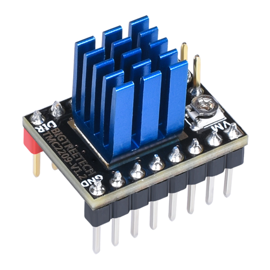
BIGTREETECH TMC2209 V1.2 - Stepper Motor Drive Module Manual
- Manual (9 pages)
Advertisement
Product Introduction
- TMC2209 is an ultra-silent motor driver IC for two-phase stepper motors. Its continuous drive current is 2A and peak current is 2.8A. Compared with TMC2208, the driving current of this IC is not only improved by 0.6a-0.8a, but also this IC increases the function of locked-motor test.
- Voltage Range: 4.75V - 28V DC
This IC have some patent technologies:
SpreadCycle™ (highly dynamic motor control chopper)
StealthChop2™ (ultra-quiet technology)
MicroPlyer™ (microstep control)
StallGuard4™ (locked-motor test)
CoolStep™ (current dynamic control) - The Flexible microPlyer interpolation unit can provide 256 microsteps. Stallguard4™locked-motor test can provide an abnormal signal when the motor rotates abnormally. CoolStep™ current dynamic control can save 75% energy. The sinusoidal control can be perfectly realized even in the system with limited pulse frequency. Since stealthChop2™ ultra-quiet technology is widely used in 3D printing, the design of these components is also compatible with existing 3D printer electronic devices, and it eliminates the expensive cost of redesigning. The module has a standard step/dir interface, it's easy to use.
Product Parameters
Product size: 15.24mm*20.32mm;
Power voltage(VM):4.75V---28V DC;
Peak current: 2.8A;
Current RMS:2A;
Microstep setting: 2, 4, 8, 16(can be divided into 256 parts)
Max microstep: 256
Operating mode: STEP/DIR or UART
Product Advantages
- The motor is difficult to lose steps.
- Ultra-quiet mode;
- The module has a large-area cooling pad, it can lower the temperature when drive is working.
- The module can prevent the motor from shaking.
- The module support locked-motor test.
- The module support STEP/DIR and UART mode.
Drive Size and Cooling Pad Size

Pin Instruction
Pin Designation

Pin Mode
| J1 | Mode | J2 | Mode | |
| 1 | (EN)Enable | 1 | (VM)Power voltage | |
| 2 | (MS1)Microstep setting | 2 | (GND)Ground | |
| 3 | (MS2)Microstep setting | 3 | (A2)Phase A | |
| 4 | (PDN)UART | 4 | (A1)Phase A | |
| 5 | (PDN)UART | 5 | (B1)Phase B | |
| 6 | (CLK)clock | 6 | (B2)Phase B | |
| 7 | (STEP)Pulse input | 7 | (VCC_IO)Logic voltage | |
| 8 | (DIR)Direction input | 8 | (GND)Ground | |
| DIAG | Diagnostic and StallGuard output. Hi level upon stall detection or; driver error. Reset error condition by ENN=high. | |||
| VREF | Analog reference voltage for current scaling or reference current for; use of internal sense resistors (optional mode) | |||
| INDEX | Configurable index output. Provides index pulse. | |||
Microstep Setting

Drive Current Formula

- Vref: 0.2V – 2.2V
- Factory default Vref: 1.2V ±0.1V
- Factory default current: 0.9A
- Potentiometer regulation instructions
Rotate the potentiometer clockwise to reduce the Vref voltage and the drive current can be reduced.
Rotate the potentiometer clockwise to reduce the Vref voltage and the drive current can be reduced.
Rotate the potentiometer counterclockwise to increase the Vref voltage and the drive current can be increased.
Operating Mode
Pin setting of UART mode
The factory has connected the UART Pin to the fourth Pin, namely the PDN_UART Pin shown on the left side of the figure below. If the fifth Pin is used as the UART Pin, the resistance shall be removed and welded to the following two pads, as shown on the right side of the figure below.
PDN is welded to select pins corresponding to UART mode;

UART mode wiring diagram

Mute mode and anti-shake mode selection
The default mode used by the factory is mute mode, as shown in the picture on the left of the following figure. If anti-shake mode is needed, remove the resistance and weld it to the following two pads, as shown in the picture on the right of the picture below.

Matters needing attentions
- Before installing the drive, make sure disconnect the power supply to prevent the drive from burning out.
- Before installing the drive, user must confirm the drive direction, to prevent back connection caused by the drive burning.
- Pay attention to the wiring sequence and I/O port when wiring. If the wrong line is connected, the driver will not work directly, please connect carefully as shown above.
- Do not plug and unplug the drive module when the device is working in order to avoid damage.
- When user install the heat sink, make sure the heat sink is not connected to the pin. We need prevent driving short circuit.
- The product is sensitive to static electricity, please handle it carefully. It is better that remove the package before using.
- Make sure to do heat dissipation treatment for the drive before using. (cooling pad, cooling fan)
Shenzhen Biqu Technology Co., Ltd.
www.BIGTREE-TECH.com
Documents / Resources
References
Download manual
Here you can download full pdf version of manual, it may contain additional safety instructions, warranty information, FCC rules, etc.
Download BIGTREETECH TMC2209 V1.2 - Stepper Motor Drive Module Manual
Advertisement


Need help?
Do you have a question about the TMC2209 V1.2 and is the answer not in the manual?
Questions and answers