Kobold NBK-R Operating Instructions Manual
Limit switch
Hide thumbs
Also See for NBK-R:
- Operating instructions manual (21 pages) ,
- Operating instructions manual (15 pages) ,
- Operating instructions manual (15 pages)
Table of Contents
Advertisement
Quick Links
Advertisement
Table of Contents

Subscribe to Our Youtube Channel
Related Manuals for Kobold NBK-R


Summary of Contents for Kobold NBK-R
- Page 1 Operating Instructions Limit switch Model: NBK-R NBK-RM NBK-RT NBK-RV/RN...
-
Page 2: Table Of Contents
Order Codes ....................12 Illustrations ....................13 Disposal ...................... 14 EU Declaration of Conformance (NBK-R/NBK-RM/NBK-RT) ...... 15 EU Declaration of Conformance (NBK-RV/RN) .......... 16 Manufactured and sold by: Kobold Messring GmbH Nordring 22-24 D-65719 Hofheim Tel.: +49 (0)6192-2990... -
Page 3: Note
Please read these operating instructions before unpacking and putting the unit into operation. Follow the instructions precisely as described herein. The instruction manuals on our website www.kobold.com are always for currently manufactured version of our products. Due to technical changes, the instruction manuals available online may not always correspond to the product version you have purchased. -
Page 4: Regulation Use
4.1 Electrical limit switch For standard applications NBK-R/NBK-RM: Bistable changeover contact fitted in a polycarbonate housing with 3 m connection cable For high temperature applications NBK-RT200/-RT400: Bistable changeover contact fitted in an aluminium die cast housing with terminal connectors. -
Page 5: Operating Principle
NBK-R... 5. Operating Principle Kobold Bypass Limit Transmitter are used for the monitoring of limit values in tanks or vessels. They are firmly attached with mounting plates and ribbon clamps to the Bypass Level Indicator, model NBK, and can be moved to any position on the bypass- tube within the measuring length. -
Page 6: Mechanical Connection
NBK-R... 6. Mechanical Connection NBK-R/NBK-RM Mount and tighten the reed switch (NBK-R, NBK-RM) - if available - on the bypass tube at the opposite side of the roller indicator with the provided fastening clamps. The height of the switch contacts may be selected at will. The cable connection must point downwards. - Page 7 The heat protection shield is situated between the switch box and the mounting bracket. ON (contact closed) level OFF (contact open) fig.3 : Mounting NBK-Rx200NO OFF (contact open) level ON (contact closed) fig.4 : Mounting NBK-Rx200NC NBK-R... K10/0523 page 7...
-
Page 8: Electrical Connection
NBK-R... 7. Electrical Connection Limit switch NBK-R, NBK-RM, NBK-RT Attention! Observe the allowed electrical ratings for the limit switch. NBK-R NBK-RT NBK-RM High Maximum values temperature Standard- contact contact Switching capacity: 60 W/VA 80 VA Switching current: 230 V 250 V... - Page 9 With switching voltages greater than 60V (NBK-RV200Nx), the aluminum housing must be firmly connected to PE. The usual protective measures must be taken for the reed contact. Fig. 6: Electrical connection NBK-RN200NO/NC Fig. 7: Protective measures for DC and AC voltage NBK-R... K10/0523 page 9...
-
Page 10: Commissioning Nbk-R
NBK-R... 8. Commissioning NBK-R Commissioning of the electrical reed switch Function of switches All switches have three connection poles (black (2), blue (3) and brown (1)). The black wire (2) is the common pole for both switching functions (N/C and N/O contact). -
Page 11: Technical Information
NBK-R... 9. Technical Information Limit contact, model NBK-R/NBK-RM Contact operation: bistable changeover contact Switching hysteresis: approximately 15 mm Max. switching capacity: 60 W/VA; 230 V ; 1 A AC/DC Contact resistance: 100 m Medium temperature: max. 100 °C Ambient temperature: max. -
Page 12: Order Codes
NBK-RM contact changeover NBK-RT200 High temperature limit contact, t 200 °C, bistable contact changeover NBK-RT400 High temperature limit contact, t 400 °C, bistable contact NBK-RV200NO Reed contact, bistable NBK-RV200NC NBK-RN200NO Reed contact bistable, NAMUR compliant NBK-RN200NC page 12 NBK-R... K10/0523... -
Page 13: Illustrations
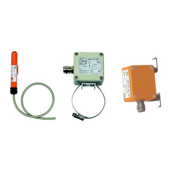
NBK-R... 11. Illustrations NBK-R/NBK-RM NBK-RT NBK-RV/RN NBK-R... K10/0523 page 13... -
Page 14: Disposal
(Cd, Hg, Li or Pb) of the heavy metal that is decisive for the classification as containing pollutants: 1. „Cd" stands for cadmium 2. „Hg" stands for mercury 3. „Pb" stands for lead 4. „Li" stands for lithium Electrical and electronic equipment page 14 NBK-R... K10/0523... -
Page 15: Eu Declaration Of Conformance (Nbk-R/Nbk-Rm/Nbk-Rt)
NBK-R... 13. EU Declaration of Conformance (NBK-R/NBK- RM/NBK-RT) We, KOBOLD Messring GmbH, Hofheim-Ts, Germany, declare under our sole responsibility that the product: Limit Contact model: NBK-R / NBK-RM / NBK-RT to which this declaration relates is in conformity with the standards noted below:... -
Page 16: Eu Declaration Of Conformance (Nbk-Rv/Rn)
NBK-R... 14. EU Declaration of Conformance (NBK-RV/RN) We, KOBOLD Messring GmbH, Hofheim-Ts, Germany, declare under our sole responsibility that the product: Magnetic Contact model: NBK-RV200NO/NC and NBK-RN200NO/NC to which this declaration relates is in conformity with the standards noted below:...
Need help?
Do you have a question about the NBK-R and is the answer not in the manual?
Questions and answers