enorossi DM 4 Use And Maintenance Manual
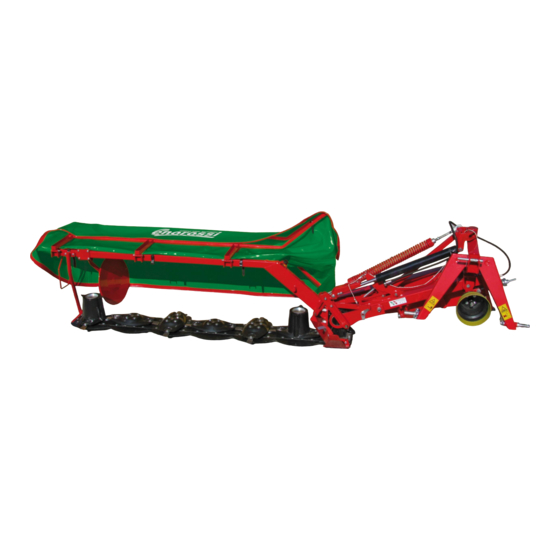
Disc mower
Hide thumbs
Also See for DM 4:
- User and maintenance manual (52 pages) ,
- Use and maintenance manual (44 pages)
Table of Contents
Advertisement
TRANSLATION
TRANSLATION
OF THE ORIGINAL
OF THE ORIGINAL
INSTRUCTIONS
INSTRUCTIONS
ENOAGRICOLA ROSSI s.r.l. - Via Cortonese s.n. - Calzolaro di Umbertide 06019 - Pg Italia Tel. (39) 075-930 22 22 Telefax (39) 075-930 23 28 -enorossi@enorossi.it info@enorossi.it
DM 4 - 5 - 6
Disc Mower
USE and MAINTENANCE MANUAL
Issue 4d – 7/2019
Advertisement
Table of Contents

Related Manuals for enorossi DM 4


Summary of Contents for enorossi DM 4
- Page 1 TRANSLATION OF THE ORIGINAL OF THE ORIGINAL INSTRUCTIONS INSTRUCTIONS Issue 4d – 7/2019 ENOAGRICOLA ROSSI s.r.l. - Via Cortonese s.n. - Calzolaro di Umbertide 06019 - Pg Italia Tel. (39) 075-930 22 22 Telefax (39) 075-930 23 28 -enorossi@enorossi.it info@enorossi.it...
-
Page 2: Ec Declaration Of Conformity
It’s forbidden reproducing or coping any parts of this manual, in e-mail: enorossi@enorossi.it - info@enorossi.it any form, without the explicit permission signed by ENOROSSI. The contents of this web: http://www.enorossi.it - http://www.enoagricolarossi.com manual can only be modified by the Manufacturer and without notifying the Customer. -
Page 3: Table Of Contents
use and maintenance manual - spare parts CONTENT EC DECLARATION OF CONFORMITY ............................... 2 INTRODUCTION ....................................5 Information about the disc mower............................... 5 Information about the manual ..............................5 Identification plate and CE mark ..............................6 Technical data and main components ............................7 Warranty ..................................... - Page 4 use and maintenance manual - spare parts...
-
Page 5: Introduction
A 2 I n f o r m a t i o n a b o u t t h e m a n u a l The ENOROSSI company (hereafter called Manufacturer) has designed and built the disc mower in obedience to appropriate safety regulations in order to protect both the operators which work with the equipment and its operating system. -
Page 6: A3 Identification Plate And Ce Mark
use and maintenance manual - spare parts The manual is updated to the characteristics of the disc mower and does not relate to earlier models. Nevertheless the Manufacturer reserves the right to modify the manual if new regulations were issued (Machine Directive) in the subject of technical content or only to improve comprehension without obligation to update the machines and preceding manuals. -
Page 7: A4 Technical Data And Main Components
A 4 T e c h n i c a l d a t a a n d m a i n c o m p o n e n t s MODEL TECHNICAL DATA DM 4 DM 4 3C DM 5 DM 6 DM 6 3C... - Page 8 use and maintenance manual - spare parts 1. Mobile chassis 10. Lifting lever 2. Multiplier (or transmission gear) 11. Slide 3. Spring 12. Stop lever 4. Safety hook 13. Protection frame 5. Jack (for lifting and lowering bar) 14. Side rake disc 6.
-
Page 9: A5 Warranty
A 5 W a r r a n t y The Enorossi company guarantees that the disc mower is exempt from defects in any kind since it has been submitted to testing before its delivery to the Customer. The warranty has a one-year validity starting from the indicated date on the fiscal document of delivery. - Page 10 use and maintenance manual - spare parts The warranty does not apply if: the machine is used by personnel inadequately trained; the instructions and rules contained in this manual are not followed; the prescribed maintenance tasks are not performed; ...
-
Page 11: Safety
use and maintenance manual - spare parts SAFETY B 1 G e n e r a l r u l e s In this manual are described those necessary for the use of the disc mower. Most accidents at work occur because the most elementary safety rules are not observed. - Page 12 use and maintenance manual - spare parts Movements: before moving it is necessary to verify that all safety and locking devices are present and integral. If one was missing or not integral, it is forbidden both the transport and the use of the equipment.
- Page 13 use and maintenance manual - spare parts 2. turn front guard I (fig. 20) backward until the fastening point with hook L; 3. bracket E must be turned upwards (fig. 22); 4. lift the bar using the tractor’s hydraulic lift, positioning lower slide M (fig. 21) at about 30-40 cm from the ground; Fig.
- Page 14 use and maintenance manual - spare parts For movements within fields, the machinery (tractor and disc mower) does not act any light or sound signals, or any signs to be displayed. Instead, if the movements are effected on public roads, it is important that the following obligations are observed: rear dimensions: the operator should apply the relevant signs on the disc mower to indicate the rear dimensions of the tractor.
- Page 15 use and maintenance manual - spare parts before reversing with the tractor, he should check that the disc mower is not in the working configuration. If It was, the equipment must be momentarily disposed in the end field configuration, that is similar to the transport one described in the chapter “Use and Operation”.
- Page 16 use and maintenance manual - spare parts do not use the equipment if on it are present breakings or damages; dangerous zone the lifting of the equipment to ground by the tractor hydraulic lift must be gently performed. A violent impact could damage components and/or structural parts of the equipment;...
-
Page 17: B4 Reasonably Foreseeable Misuse And Limit Of Employ
use and maintenance manual - spare parts The working process must be stopped immediately if: the equipment is near to resistant objects as manholes, guard-rails, railway tracks etc. The impact could cause the blade breaking and its splinters will be thrown over the place at high speed; wires, chains or anything else are twisted round the one or more disc rotors. -
Page 18: B5 Operator's Responsibility And Safety
use and maintenance manual - spare parts the parking brake, remove the starting keys from the dashboard and provide to eject the intruder. At the same way during the adjusting and/or maintenance tasks, the people must not stay or move in the proximity of the equipment. Do not use the disc mower if: the forage to mow results damp. - Page 19 use and maintenance manual - spare parts Further to the instruction in this manual, there are adhesive labels on different parts of the equipment to make the job easier for the operators and that. These labels represent the safety rules to observe. They have the purpose to draw attention and to inform the personnel about them dangerous grade.
- Page 20 use and maintenance manual - spare parts H. danger of upper or lower limb amputations. absolutely forbidden to approach hands or feet to rotating discs when these are operating. The interventions to discs must be performed with the P.T.O. disengaged, the tractor engine off and the keys removed from the dashboard;...
-
Page 21: B6 Noisiness
use and maintenance manual - spare parts B 6 N o i s i n e s s The noise produced from the equipment is due to mechanical movements of its rotating discs. Therefore, it results of low intensity respect to ones produced from the tractor on which it is installed. -
Page 22: Installation
use and maintenance manual - spare parts INSTALLATION C 1 A s s e m b l y o f d i s c m o w e r To facilitate shipments of the machines, several parts have been disassembled to reduce the shipping dimensions. To reassemble, proceed as follows: open the case and lay the mower disc bar flat, as indicated in fig.C1;... - Page 23 use and maintenance manual - spare parts 2. Assembly of the protection bar: Position the protection bar E in support A (fig.C4b) and fasten it with six screws F (screw T.E. M10x35), six washers, and six self- locking nuts G M10 (only on DM-P series).
- Page 24 use and maintenance manual - spare parts fig.C5 3. Assembly of the support rod and support for high grass: Mount support rod H and support for high grass W (fig.C5), and fasten respectively by screws Y (T.E. M10x70 + 2 self-locking nut M10 and washers), and screws V (T.E.
- Page 25 use and maintenance manual - spare parts 5. Assembly of the internal cone disc: mount internal cone disc M (fig. C7) so that the largest dimension is oriented perpendicular to that of the nearby disc, as shown in figure. fig.C7 fig.C8a fig.C8b 6.
- Page 26 use and maintenance manual - spare parts 8. Assembly of the belt protection case: Mount case U (fig.C10), fasten with screws V (T.E. M10x120), washers and self-blocking nuts (M10). 9. Assembly of the compensating spring: Hook spring W (fig.C11) on pin Y of the protection support and fasten it with an elastic pin Ø...
- Page 27 use and maintenance manual - spare parts 11. Assembly of protection guards: Mount front guard H (fig.C14) on the three hinges and fasten with screws I (T.E. M10x85) and self- locking nuts M10 + washer. Mount rear guard L (fig.C14) with six screws M (TTQS M10x25) and self-locking nuts M10.
-
Page 28: C2 Installation Of The Disc Mower To The Tractor And Working Configuration
use and maintenance manual - spare parts 15. Assembly of bearing foot (fig.20): Place the support of bearing foot (49) on the equipment chassis, as shown in figure, and fix by using the relevant screws (48) and nuts (46); Remove the split pin (50) and the safety pin (51) from the bearing foot. – Insert the bearing foot (52) in its support (49). - Page 29 use and maintenance manual - spare parts 2. Insert the adjustable tie rod of tractor C in the seat of the three point of the disc mower. Insert the locking pin (D - fig.C21A) and lock it with the relative safety-pin; 3.
- Page 30 use and maintenance manual - spare parts 7. Adjustment of frame height from the ground a. for tractors equipped with hydraulic lift position control: Position the tractor on level ground and lower the hydraulic lift until the lifting lever F (fig.C24) is positioned at a distance of 8/10 mm from the edge, as shown in (fig.C24). After that, set the lift control from the tractor driver seat.
-
Page 31: C3 Removal Of The Mower From The Tractor
use and maintenance manual - spare parts C 3 R e m o v a l o f t h e m o w e r f r o m t h e t r a c t o r 1. -
Page 32: C4 Storage Of The Disc Mower
use and maintenance manual - spare parts C 4 S t o r a g e o f t h e d i s c m o w e r Park the equipment in a safe and covered site and that it be a solid and flat surface. Nota: avoid to park the equipment in sites not covered because the humidity, also if it does not effect its operation, allows in way more evident the rusty formation on the parts. -
Page 33: Operation And Use
use and maintenance manual - spare parts OPERATION and USE D 1 P r e l i m i n a r y c h e c k s An appropriate and optimum use of the disc mower, other than to prevent the accidents, is the one way to obtain a high productivity so to individuate its true potentiality and performances. -
Page 34: D2 Operation
use and maintenance manual - spare parts pull cord O (fig.C30) to free the bar from safety hook P1; lower mower using hydraulic cylinder until it reaches the work position; turn the front tarpaulin carrier over forward (fig.C31). Check the height of the chassis from the ground. -
Page 35: D3.1 Adjustment Of Cutting Height
use and maintenance manual - spare parts the advancement speed must be appropriate for the working conditions. Before changing of direction reduce the speed; IMPORTANT : do not mow in extremely stony or rocky areas ; end field: it will not be necessary to put the disc mower in transport configuration, but it will be enough to lift the bar with the discs, as shown fig.C32. -
Page 36: D3.2 Adjustment Of The Side Rake Disc
use and maintenance manual - spare parts D 3 . 2 A d j u s t m e n t o f t h e s i d e r a k e d i s c Position the rake disc in order to have the greatest distance between the uncut forage and the windrow. -
Page 37: D3.4 Wear Proof Skids Kit
use and maintenance manual - spare parts D 3 . 4 W e a r p r o o f s k i d s k i t The cutter bar has been designed to assembled wear proof skids. They are offered as an option. The kit includes: - Longer screws (1) and nut (3);... -
Page 38: Maintenance
use and maintenance manual - spare parts MAINTENANCE E . 1 M a i n t e n a n c e i n s t r u c t i o n s The Manufacturer, following to operational tests, has foreseen some maintenance programmes which permit, if respected and performed with care by the Customer, to maintain unchanged the machine efficiency and capacity preserving the disc mower from every operating damages. -
Page 39: Checks, Adjustments And Replacements
The discs, blades, and fastening screws are made of a special high-quality steel and heat- treated to increase their durability and resistance to wear. Worn or damaged parts must be immediately replaced with ENOROSSI original parts, otherwise it will not be possible to make any warranty claims or requests. - Page 40 - spare parts Use ENOROSSI original spare parts. For your safety, and for a better cutting quality, make systematic checks of the wear condition of the blades before every use of the mower. Change blades immediately if they are damaged, because if work is done occasionally in difficult conditions, the risk of accidents increases, the cutting quality decreases, and vibrations may also damage the disc support.
-
Page 41: Lubrification
use and maintenance manual - spare parts E . 3 L u b r i f i c a t i o n Lubrication of the mowing bar (contains oil) Oil level check: check the oil level before starting to mow for the first time, and in normal conditions (no oil leaks) every year. Lift the bar using the hydraulic hitch as indicated in fig. - Page 42 use and maintenance manual - spare parts quantity: fig.E9 DM4: 2 litres DM5: 2.5 litres DM6: 3 litres NOTE: during work, it is normal for the oil in the tank and the gear case to heat up; there are no problems if the discs turn freely when turned by hand.
- Page 44 ENOAGRICOLA ROSSI s.r.l. 06019 Calzolaro di Umbertide Perugia Italia Tel. (39) 075-930 22 22 - Telefax (39) 075-930 23 28 e-mail: enorossi@enorossi.it – info@enorossi.it web: http://www.enorossi.it - http://www.enoagricolarossi.com...
Need help?
Do you have a question about the DM 4 and is the answer not in the manual?
Questions and answers