Table of Contents
Advertisement
Quick Links
TABLE OF CONTENTS
1 Safety Precautions----------------------------------------------- 3
1.1. General Guidelines---------------------------------------- 3
1.2. Caution For AC Cord (For EB) ------------------------- 4
1.3. Safety Parts Information --------------------------------- 4
2 Warning -------------------------------------------------------------- 5
to Electrostatically Sensitive (ES) Devices---------- 5
(PbF)---------------------------------------------------------- 5
3 Specifications ----------------------------------------------------- 7
4 Location of Controls and Components ------------------- 8
5 Troubleshooting Guide ----------------------------------------- 9
5.1. No Power ---------------------------------------------------- 9
5.2. LED Blinking ----------------------------------------------- 11
5.3. No Sound (Large humming noise) -------------------12
5.4. Turntable Does Not Operate (No rotation) ---------13
5.5. LED No Illumination--------------------------------------14
6 Disassembly and Assembly Instructions ---------------16
Direct Drive Turntable System
SL-1200MK7PP
Model No.
SL-1210MK7EB
SL-1210MK7EG
Product Color: (K)...Black Type
PAGE
6.1. Types of Screws------------------------------------------ 17
6.2. Disassembly Flow Chart ------------------------------- 18
6.3. Main Components and P.C.B. Locations----------- 18
Ass'y--------------------------------------------------------- 19
Knob--------------------------------------------------------- 19
6.6. Disassembly of Insulators------------------------------ 19
6.7. Disassembly of Bottom Chassis Ass'y-------------- 20
6.8. Disassembly of DC Motor------------------------------ 20
6.9. Disassembly of Phono Out P.C.B. ------------------- 20
Knob and Armrest Ass'y-------------------------------- 21
6.11. Disassembly of Main P.C.B. --------------------------- 22
6.12. Disassembly of Pitch P.C.B. Ass'y------------------- 24
6.14. Disassembly of SMPS P.C.B. ------------------------- 25
© Panasonic Corporation 2019. All rights reserved.
Unauthorized copying and distribution is a violation
of law.
PSG1904002CE
A6
PAGE
Advertisement
Table of Contents

Related Manuals for Technics SL-1200MK7PP


Summary of Contents for Technics SL-1200MK7PP
-
Page 1: Table Of Contents
PSG1904002CE Direct Drive Turntable System SL-1200MK7PP Model No. SL-1210MK7EB SL-1210MK7EG Product Color: (K)...Black Type TABLE OF CONTENTS PAGE PAGE 1 Safety Precautions----------------------------------------------- 3 6.1. Types of Screws------------------------------------------ 17 1.1. General Guidelines---------------------------------------- 3 6.2. Disassembly Flow Chart ------------------------------- 18 1.2. Caution For AC Cord (For EB) ------------------------- 4 6.3. - Page 2 6.15. Disassembly of Operation Ass’y --------------------- 25 6.16. Disassembly of SW P.C.B.----------------------------- 26 6.17. Disassembly of Panel P.C.B. -------------------------- 26 6.18. Disassembly of Strobe P.C.B. ------------------------- 26 7 Measurements and Adjustments -------------------------- 27 7.1. Service Mode Startup Procedure -------------------- 27 7.2.
-
Page 3: Safety Precautions
1 Safety Precautions 1.1. General Guidelines 1. IMPORTANT SAFETY NOTICE There are special components used in this equipment which are important for safety. These parts are marked by in the Schematic Diagrams, Circuit Board Layout, Exploded Views and Replacement Parts List. It is essential that these critical parts should be replaced with manufacturer’s specified parts to prevent X-RADIATION, shock, fire, or other hazards. -
Page 4: Caution For Ac Cord (For Eb)
1.2. Caution For AC Cord (For EB) A 10-ampere fuse is fitted in this plug. (10 ampere) Figure 1-2 1.3. Safety Parts Information Safety Parts List: There are special components used in this equipment which are important for safety. These parts are marked by in the Schematic Diagrams, Exploded View &... -
Page 5: Warning
2 Warning 2.1. Prevention of Electrostatic Discharge (ESD) to Electrostatically Sensi- tive (ES) Devices Some semiconductor (solid state) devices can be damaged easily by static electricity. Such components commonly are called Elec- trostatically Sensitive (ES) Devices. The following techniques should be used to help reduce the incidence of component damage caused by electrostatic discharge (ESD). - Page 6 Service caution for repair work using Lead Free Solder (PbF) • The lead free solder has to be used when repairing the equipment for which the lead free solder is used. (Definition: The letter of “PbF” is printed on the PCB using the lead free solder.) •...
-
Page 7: Specifications
3 Specifications General Power supply AC 120 V, 60 Hz (1200MK7PP) AC 110 V to 240 V, 50/60 Hz (1210MK7EB/EG) Power consumption 8.0 W (Power ON) Approx 0.2 W (Power OFF) Dimensions (W x H x D) 453 mm x 169 mm x 353 mm (17 - ”... -
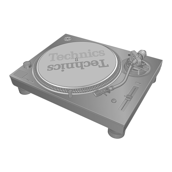
Page 8: Location Of Controls And Components
4 Location of Controls and Components Arm clamp Arm rest EP record adaptor Front Centre spindle Head shell stand START-STOP button Balance weight Stylus pressure Tone arm ON/OFF (power) control Locking nut Strobe light Head shell Arm lock Anti-skating control Cue lever Speed select buttons Arm-height... -
Page 9: Troubleshooting Guide
5 Troubleshooting Guide 5.1. No Power No power AC power supply cord Plug the cord in firmly. plugged in? Is AC INLET AC power supply cord part damaged? damaged? Replace AC CORD. Replace SMPS PCB. (No rotation, spinning around, etc.) Is Power Knob operating normally? - Page 10 No power (from the previous section) Is the correct voltage presented between CK2111 (+24V) and Replace MAIN PCB. CK2113 (GND) on MAIN PCB to confirm Power knob operation? CK2111 CK2113 (+22.8 to +25.2 V) (GND) MAIN PCB CK2113 Pin 3 of IC2105 Pin 3 of IC2102 (GND) (+4.6 to +5.0 V)
-
Page 11: Led Blinking
5.2. LED Blinking LED Blinking of LED Blinking of 2 times LED Blinking of 33 LED 45 LED both 33 and 45 LED Abnormal speed or Abnormal FG signal or Abnormal +24 V. reverse rotation Abnormal Hallsensor signal Replace MAIN PCB. Is the pulse signal (0-5V) output between... -
Page 12: No Sound (Large Humming Noise)
5.3. No Sound (Large humming noise) No sound (Large humming noise) Are the PHONO cable Connect the PHONO cable and and PHONO earth Lead PHONO earth Lead correctly. correctly connected? Is the PHONO cable or PHONO earth Lead damaged? Is the PHONO output terminal or PHONO earth terminal damaged? -
Page 13: Turntable Does Not Operate (No Rotation)
5.4. Turntable Does Not Operate (No rotation) Turntable does not operate (No rotation) Does turntable rotate smoothly NO (Not rotated smoothly) when rotated with hand in power OFF condition? Is the turntable correctly YES (rotated) attached? Replace MAIN PCB. Attach the turntable correctly. Does the turntable rotate when the power is turned ON after the connector... -
Page 14: Led No Illumination
5.5. LED No Illumination 5.5.1. Strobe light --- No Illumination X1001 : 17.6904MHz Strobe light --- No Illumination Is the clock (X1001) for microcomputer (IC1001) oscillated? Replace MAIN PCB. MAIN PCB IC1001 microcomputer Pin 1 (Probe) Pin 2 (GND) X1001 : 17.6904MHz Is the correct voltage presented at Pin 3 (CK2152) or... - Page 15 5.5.2. Stylus light --- No Illumination Stylus light --- No Illumination Turn the Unit ON and press the stylus light to rise up. Does stylus light illuminate? Replace STYLUS LIGHT UNIT ASS’Y. Normal condition. Finish. 5.5.3. LED for speed select button ([33] or [45]) --- No Illumination LED for 33 or 45 --- No Illumination Is the clock (X1001) for microcomputer...
-
Page 16: Disassembly And Assembly Instructions
6 Disassembly and Assembly Instructions Caution Note: • This section describes the disassembly and/or assembly procedures for all major printed circuit boards & main compo- nents for the unit. (You may refer to the section of “Main components and P.C.B Locations” as described in the service manual) •... -
Page 17: Types Of Screws
Note for assembly and disassembly • Replace the PCB, etc. from the bottom cover side. • When turning the unit over, be sure to close the dust cover or put a cardboard as a base, and place the unit on a soft thick cloth or cushion, etc, to prevent cracking. -
Page 18: Disassembly Flow Chart
6.2. Disassembly Flow Chart Slip Mat Ass'y and Turntable Ass’y Insulators Bottom Chassis Ass’y Main P.C.B. Pitch Knob and Pitch P.C.B. Ass’y Power SW Knob Stylus Light Unit Ass’y Phono Out P.C.B. SMPS P.C.B. Operation Ass’y DC Motor Unit (With LED P.C.B.) and Stylus SW P.C.B. -
Page 19: Disassembly Of Slip Mat Ass'y And Turntable Ass'y
6.4. Disassembly of Slip Mat Ass’y Note: When replacing the Pitch Knob, insert the Pitch Knob at the edge of the Pitch Control Volume. (Inserting it and Turntable Ass’y at the center will increase the load due to the distance from the fixing screw of the Pitch Control Volume). -
Page 20: Disassembly Of Bottom Chassis Ass'y
6.7. Disassembly of Bottom Chas- 6.9. Disassembly of Phono Out sis Ass’y P.C.B. • Refer to “Disassembly of Slip Mat Ass’y and Turntable • Refer to “Disassembly of Slip Mat Ass’y and Turntable Ass’y”. Ass’y”. • Refer to “Disassembly of Insulators”. •... -
Page 21: Disassembly Of Tone Arm All Ass'y, Queuing Knob And Armrest Ass'y
6.10. Disassembly of Tone Arm All Step 6 Remove 2 screws and Arm Wire Ground Plate. Step 7 Unsolder 5P Wire on Phono Out P.C.B.. Ass’y, Queuing Knob and Arm- Step 8 Remove Phono Out P.C.B.. rest Ass’y Caution: During assembling of 5P Wires, ensure wires properly seated on top of arm wire cushion. -
Page 22: Disassembly Of Main P.c.b
6.10.2. Removing the Armrest Ass’y Note: When using a commercially sold Board Ratchet Driver, use a driver suitable for working in the gap of 25 Step 1 Turn the arm height adjustable ring to raise to the height of 6mm (max). Step 2 Remove screw. - Page 23 Step 5 Detach 5P Wire at connector (P2101) on Main P.C.B.. • 3P wire is soldered directly at P1006 on Main P.C.B. in some Step 6 Detach 11P Wire at connector (P3101) on Main P.C.B.. units. Step 7 Detach 2P Wire at connector (P2103) on Main P.C.B.. •...
-
Page 24: Disassembly Of Pitch P.c.b. Ass'y
6.12. Disassembly of Pitch P.C.B. Step 3 Remove 2 screws. Step 4 Remove Pitch P.C.B. Ass’y as arrow shown. Ass’y • Refer to “Disassembly of Slip Mat Ass’y and Turntable Ass’y”. • Refer to “Disassembly of Pitch Knob and Power SW Knob”... -
Page 25: Disassembly Of Smps P.c.b
Step 4 Remove 3 screws. Step 4 Remove 7 screws. Step 5 Detach 2P Wire at connector (P401) on Stylus SW Step 5 Detach 5P Wire at connector (P1730) on SMPS P.C.B.. P.C.B.. Step 6 Remove SMPS P.C.B.. Step 6 Remove Stylus SW P.C.B.. 6.14. -
Page 26: Disassembly Of Sw P.c.b
6.17. Disassembly of Panel P.C.B. Note: When assembing the Operation Ass’y, insert as arrow shown • Refer to “Disassembly of Slip Mat Ass’y and Turntable Ass’y”. • Refer to “Disassembly of Insulators”. • Refer to “Disassembly of Bottom Chassis Ass’y”. •... -
Page 27: Measurements And Adjustments
7 Measurements and Adjustments Use the Service Mode to adjust this unit (PITCH ADJ Center Position Adjustment and Automatic Adjustment). • PITCH ADJ center position adjustment: Perform this adjustment when the PITCH CONTROL UNIT (PITCH PCB) or MAIN PCB is replaced. •... -
Page 28: Pitch Adj Center Position Adjustment
7.2. PITCH ADJ Center Position Adjustment <Status Check before Adjustment> • Check if the unit is in the following conditions. Item Condition Remarks Turntable Unit Attached to the main unit Slip Mat Ass’y Attached to the main unit Record Not present Tone Arm Fixed to the arm rest <PITCH ADJ Center Position Adjustment Procedure>... -
Page 29: Automatic Adjustment
7.3. Automatic Adjustment This adjustment is automatically performed based on the learning function of the microcomputer. The following items of measurement/adjustment are automatically performed. • Rotation accuracy (The reference voltage value) • Start-up time • FG Wow and flutter • Stop angle •... -
Page 30: Block Diagram
8 Block Diagram TONE ARM UNIT PHONO OUT PCB SMPS PCB MAIN PCB JK4001 RESISTANCE DIVISION FUSE 2A P1730 P2101 STYLUS LIGHT UNIT STYLUS SW PCB (STYLUS LED PCB) FUSE 0.3A P2103 P900 P400 P401 REVERSE BLUE AC IN RESISTANCE DIVISION DC MOTOR UNIT Motor PWM+ Driver... -
Page 31: Wiring Connection Diagram
PHONO OUT P.C.B. SMPS P.C.B. DC MOTOR UNIT WHITE BLUE TO TONE ARM ALL ASS’Y BROWN PIPE BLACK TO EARTH WIRE P1700 AC120 V, 60 Hz (PP) AC110 V - 240 V, 50/60 Hz (EB/EG) SL-1200MK7PP, SL-1210MK7EB/EG WIRING CONNECTION DIAGRAM... -
Page 32: Exploded View And Replacement Parts List
10 Exploded View and Replacement Parts List 10.1. Electrical Replacement Parts List Safety Ref. Part No. Part Name & Qty Remarks Description PRINTED CIRCUIT BOARDS PCB1 TNPA7005AA MAIN P.C.B. PRINTED CIRCUIT BOARDS PCB2 TNPA7007AA STYLUS SW P.C.B. PRINTED CIRCUIT BOARDS PCB3 TNPA7008AA STROBE P.C.B. -
Page 33: Mechanical Replacement Part List
10.2. Mechanical Replacement Part List Safety Ref. Part No. Part Name & Qty Remarks Description Safety Ref. Part No. Part Name & Qty Remarks TXP0100 TONEARM ALL ASSY Description 21-1 RMH0241-K1 QUEUING KNOB CABINET 21-2 RYQ1630-K1 ARMREST ASSY CHASSIS 21-3 TZSM04009 REST SCREW... - Page 34 OI (En) TAQ0036 SIGNAL CABLE ASSY TPH0339 EP ADAPTER UNIT BLACK TTFA0454 DUST COVER UNIT TTV0022 CARTRIGE SCREW TYL0295 BALANCE WEIGHT ASSY TYL0332 TURNTABLE ASSY EB EG TYL0333 TURNTABLE ASSY TYL0330 SLIP MAT ASS'Y TYL0331 SHELL ASS'Y TBMA7331 TECHNICS LABEL...
-
Page 35: Cabinet Parts Location
10.3. Cabinet Parts Location 1 21-1 21-2 21-3 (STROBE P.C.B.) (SW P.C.B.) (STYLUS SW P.C.B.) (PHONO OUT P.C.B.) (PANEL P.C.B.) (SMPS P.C.B.) (MAIN P.C.B.) (PITCH P.C.B.) SL-1200MK7PP SL-1210MK7EB/EG NOTE: " * " PART IS NOT SUPPLIED. CABIENT DRAWING... -
Page 36: Cabinet Parts Location
10.4. Cabinet Parts Location 2 SL-1200MK7PP SL-1210MK7EB/EG NOTE: " * " PART IS NOT SUPPLIED. CABIENT DRAWING... -
Page 37: Packaging
10.5. Packaging ACCESSORIES BAG *1 : P7 (FOR EB ONLY) SL-1200MK7/ (FOR PP ONLY) SL-1210MK7 (FOR EG ONLY) *1 : P7 FRONT POLYFOAM *1 : P7 REAR POLYFOAM SL-1200MK7PP SL-1210MK7EB/EG *2 : THIS PART IS NOT SUPPLIED. PACKAGING DRAWING MMH1904...
Need help?
Do you have a question about the SL-1200MK7PP and is the answer not in the manual?
Questions and answers