Table of Contents
Advertisement
Quick Links
Advertisement
Table of Contents

Related Manuals for Poweramp LMP Series


Summary of Contents for Poweramp LMP Series
- Page 1 LMP-Series Dock Leveler Owner’s/User’s Manual POWERAMP • Division of Systems, Inc. • W194 N11481 McCormick Drive • Germantown, WI 53022 800.643.5424 • fax: 262.257.7399 • www.docksystemsinc.com • techservices@docksystemsinc.com Printed in U.S.A. Manual No. 4111-0013 Copyright 2014 December 2014 ©...
-
Page 2: Table Of Contents
Table of Contents Page Safety Recognize Safety Information ............. 1 General Operational Safety Precautions ..........1 Operational Safety Precautions ............2 Maintenance Safety Precautions ............4 Safety Decals ..................5 Owner’s/User’s Responsibilities ............6 Introduction General Information ................7 Dock Leveler Stock Specifications ............. 7 Component Identification .............. -
Page 3: Safety
SAFETY Recognize Safety Information General Operational Safety Precautions Safety-Alert Symbol The Safety-Alert Symbol identifies important safety messages on equipment, safety signs, in manuals, or elsewhere. When you see this symbol, be alert to the possibility of personal injury or death. Follow Read and understand the operating instructions and the instructions in the safety message. -
Page 4: Operational Safety Precautions
SAFETY Operational Safety Precautions Learn the safe way to operate this equipment. Read and understand the manufacturer’s instructions. If you have any questions, ask your supervisor. Stay clear of dock leveling device when transport Chock/restrain all transport vehicles carriers. vehicle carrier is entering or leaving area. Never remove the wheel chocks until loading or unloading is finished and transport vehicle driver has been given permission to drive away. - Page 5 SAFETY Do not use dock leveling device if transport vehicle is too high or too low. Do not overload the dock leveling device. Do not operate any equipment while under the influence of alcohol or drugs. Do not leave equipment or material unattended on dock leveling device.
-
Page 6: Maintenance Safety Precautions
SAFETY Maintenance Safety Precautions DO NOT grind or weld if hydraulic fluid or other flammable liquid is present on the surface to be ground or welded DO NOT grind or weld if uncontained hydraulic fluid or other flammable liquid is present. Stray sparks can ignite spills or leaks near the work area. -
Page 7: Safety Decals
SAFETY Safety Decals Every 90 days (quarterly) inspect all safety labels and tags to ensure they are on the dock leveler and are easily legible. If any are missing or require replacement, please call 1-800-643-5424 DANGER CRUSH HAZARD for replacements. Maintenance prop must support leveler behind bar. -
Page 8: Owner's/User's Responsibilities
OWNER’S/USER’S RESPONSIBILITIES 1. The owner/ user should recognize the inherent dangers of the interface between the loading dock and the transportation vehicle. The owner/ user should, therefore, train and instruct all operators in the safe operation and use of the loading dock equipment in accordance with manufacturer’s recommendations and industry standards. -
Page 9: Introduction
40,000 lb (18 144 kg) mechanical dock leveler. * CIR (Comparative Industry Rating) Designed by Poweramp to be a marvel of simplicity Call Poweramp for your specific needs. and efficiency, your dock leveler, when properly installed, will provide many years of trouble- free performance with an absolute minimum of maintenance. -
Page 10: Component Identification
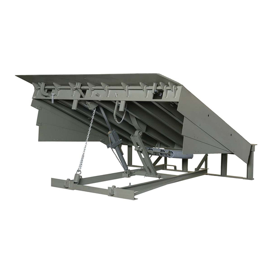
INTRODUCTION Component Identification G H J A — Lip F — Platform Release Ring L — Platform Maintenance Prop R— Safety Leg Linkage B — Lip Prop G — Ratchet Pawl M— Hold-Down Mechanism S — Safety Leg Pull Ring C —... -
Page 11: Installation
INSTALLATION Prepare Pit A— Distance (Pit Width) B — Distance (Dock Floor-to-Pit C — Distance (Pit Length) D — Distance (Pit Corner-to-Corner) (Front and Rear) Floor) (All Four Corners) (Both Sides of Pit) (Top, Bottom, and Both Sides) Before lowering the dock leveler into the pit, the following must be performed: Post safety warnings and barricade the work 1. -
Page 12: Prepare Dock Leveler
Prepare Dock Leveler A— Lifting Bracket (2 used) B — Shipping Bands Poweramp dock levelers are designed with installation in mind. Each unit is shipped with lifting brackets (A) fastened to the platform side joists. The dock leveler is heavy. Use a lifting device and chains with the appropriate lifting capacity and reach. - Page 13 INSTALLATION Placard Installation Instructions • Owner is responsible for the installation and placement of placards. • Make sure placard is in plain view of dock leveler operations. • Suggested placement of placard is near control box attached to electrical conduit by using nylon tie. If there is no control box present, mount placard on wall to the immediate left of leveler at eye level.
-
Page 14: Install Dock Leveler
INSTALLATION Install Dock Leveler Shim Stacking Methods A— Distance (Leveler Frame H— Rear Hinge Frame Angle Height) I— Shim Locations (Under Lift Arm) B— Shim Locations (Under Rear J— Distance (Dock Floor to Floor) Vertical Supports) K— Shim Stack C— Shim Location (Under L—... - Page 15 INSTALLATION NOTE: Systems, Inc. dock levelers are designed with a nominal 1/2 in. (12.7 mm) shimming The dock leveler is heavy. Use chains and a distance to allow for pit inconsistencies. lifting device with the appropriate lifting capacity 1. Determine height of shim stack (K) for each shim and reach.
- Page 16 (if equipped) will not bind during dock leveler operation. 12. If leveler cannot be squared and made level as instructed in steps 8 – 10, contact Poweramp 9. If gap (D) cannot be obtained equally at both Technical Services.
- Page 17 6 in. (152 mm) space or remove shims as necessary. Raise and lower between each weld. platform again. If platform still binds, contact Poweramp Technical Services for further Alternate welding locations to distribute heat. Welding sequentially from one end to the other instructions.
- Page 18 INSTALLATION A— Safety Leg Chain Pull Ring B— Platform Maintenance Prop C — Shim Location (Under Lift Arm Pivot) D — Locking Device E— Lip Prop F— Platform Release Ring 21. Pull the release ring to raise platform. Engage 25. Remove the lifting brackets from the platform the platform maintenance prop (B) in the service side joists.
-
Page 19: Operation
OPERATION Theory 1 — Lip 6 — Hold Down Release Ring 10 — Platform Maintenance Prop 15 — Safety Leg Below Dock 2 — Lip Maintenance Prop 7— Ratchet Pawl 11— Main Base Frame Control 3 — Platform 8— Ratchet Bar 12 —... -
Page 20: Operating Instructions
OPERATION Operating Instructions 12 in. (305 mm) Stay clear of dock leveler when transport vehicle is entering or leaving dock area. DO NOT raise or lower the dock leveler if anyone is under or in front of leveler. 12 in. (305 mm) Keep hands and feet clear of pinch points. -
Page 21: Ramp Loading/Unloading Instructions
OPERATION Operating Instructions — Continued Ramp Loading/Unloading Instructions NOTE: If end unloading is required, see End 7. Make sure that the lip is fully extended and Loading/Unloading Instructions on page 20. supported on the transport vehicle along the entire width of the platform with at least 4 in. (102 mm) 1. -
Page 22: End Loading/Unloading Instructions
OPERATION Operating Instructions — Continued End Loading/Unloading Instructions NOTE: End loading or unloading can be done with the dock at the cross-traffic position or below-dock position depending on the height of the transport vehicle bed. 1. Check to make sure transport vehicle is positioned squarely against dock bumpers. -
Page 23: Maintenance
MAINTENANCE Service Dock Leveler Safely A— Platform Release Ring B — Platform Maintenance C— Lip Prop D— Prop Pin and Clip E— Safety Leg Pull Chain Prop Whenever maintenance is to be performed under the dock leveler platform, support the platform with the Always post safety warnings and barricade the platform maintenance prop (B). -
Page 24: Periodic Maintenance
MAINTENANCE Periodic Maintenance • A —Lip Hinge Lug Area D — Platform Lug Area G — Lift Arm Pivot K — Lip Assist Pin B — Maintenance Prop Pivot E — Lift Arm Roller Bushing H — Hold-Down Pivot/Pulley L — Hold Down-to-Platform Pin C —... - Page 25 MAINTENANCE Regular maintenance must be performed on a weekly and quarterly schedule. Follow all safety precautions. Weekly Maintenance Quarterly Maintenance • Operate the dock leveler through the complete • Weekly Maintenance operating cycle to maintain lubrication. • Lubricate the following areas with light-weight machine oil: NOTE: To thoroughly inspect the platform hinge area, position the platform in the full...
-
Page 26: Adjustments
ADJUSTMENTS Adjust Lift Arm Spring and Lip Assist Spring Tension A — Jam Nut C — Lip Assist Spring E — Lift Spring Bolt B — Adjustment Nut D — Lift Springs F — Hold-Down Mechanism The platform maintenance prop MUST be in the Always post safety warnings and barricade the service position when working under the dock work area at dock level and ground level to prevent... - Page 27 ADJUSTMENTS NOTE: Adjusting the tension of lift springs (D) usually 3. After lift spring adjustment is completed, check requires that the lip assist spring (C) also be operation of the lip. adjusted. • If the lip folds before the platform can be If the platform does not rise fully and/or lip does not walked down, tension of lip assist spring (C) extend fully, the lift spring tension may be set too low.
-
Page 28: Non-Adjustable Lip Stop
ADJUSTMENTS Adjust Lip Stop Bolt Always post safety warnings and barricade the work area at dock level and ground level to prevent unauthorized use of the dock leveler before maintenance is complete. Failure to do this may result in serious personal injury or death. Always stand clear of the dock leveler lip when working in front of the dock leveler. -
Page 29: Troubleshooting
Dock leveler binds. Check for visible obstructions that could cause binding. Check weather seal if equipped. If no obstructions found, call Poweramp Technical Services. See inside back cover for phone number and address. Platform rises slowly or Heavy object(s) on platform. Remove object(s) from platform. - Page 30 TROUBLESHOOTING Symptom Possible Cause Solution Platform rises to full Lip assist chain Connect or replace chain. height, but lip does not disconnected or broken. fully extend. Insufficient main spring Increase tension on main lift springs. (See Adjust tension. Lift Arm Spring and Lip Assist Spring Tension in the Adjustments section.) Insufficient lip assist force.
-
Page 31: Parts
PARTS Hold-Down Mechanism Item Quantity Part Number Description DOTH-2563 Hold Down Assembly Complete, 31.5” Ratchet Bar DOTH-2564 Hold Down Assembly Complete, 34.5” Ratchet Bar DKIT-2575 Ratchet Bar and Pawl Assembly 31.5” Ratchet Bar DKIT-2576 Ratchet Bar and Pawl Assembly 34.5” Ratchet Bar 1751-0043 Decal, Warning DOTH-2559... -
Page 32: Frame Components
PARTS Frame Components 4111-0013 — December 2014... - Page 33 PARTS Frame Components Item Quantity Part Number Description DFRA-____ Frame, Welded Assembly DFRA-____ Frame, Clean Sweep, Welded Assembly (Optional) DOTH-2555 Spring, Snubber DOTH-2418 Hook, S. DPLA-2128 Chain, Lip Assist Link DOTH-2416 Link,Lap DFRA-0326 Plate, Spring Tensioner 6 foot long DFRA-0327 Plate, Spring Tensioner 8 foot long DOTH-2222 Washer...
-
Page 34: Platform Components
PARTS Platform Components M N R P G H i 4111-0013 — December 2014... - Page 35 PARTS Platform Components DPLA-0338 LIP BANGER ASSY. DPLA-0341 DPLA-0343 BELOW DOCK CONTROL ASSY. DOTH-2382 PIN, COTTER LIP SHAFTS DPLA-0316 6.0 FOOT DPLA-0394 6.5 FOOT DPLA-0317 7.0 FOOT DPLA-0353 BELOW DOCK CHAIN ASSY. DPLA-0360 BDC PUSH ROD ASSY DOTH-2060 BOLT SHOULDER DOTH-2131 LOCK NUT DOTH-6406...
-
Page 36: Toe Guard/Weather Seal-Optional
Toe Guard/Weather Seal—Optional Item Quantity Part Number Description DOTH-2818 Channel, Weather Seal, 84” DOTH-2824 T-Rubber, Weather Seal, 84” DOTH-2820 Extrusion, Brush Weather Seal, 84” DOTH-2822 Brush Weather Seal, 1.58” x 84” DOTH-2043 Cap Screw DOTH-2207 Washer DOTH-2131 Nut, Nylon Lock Toe Guard / Weather Seal Options DKIT-9178 Full Range Toe Guard Assembly, 5’... - Page 37 PARTS This page intentionally left blank 4111-0013 — December 2014...
- Page 38 NOTES This page intentionally left blank 4111-0013 — December 2014...
-
Page 39: Miscellaneous
Name ___________________________________ number decal (A) becomes lost or damaged. Address _________________________________ Also, write down Poweramp ’s job number, the company that installed the dock leveler, and the _________________________________ original owner’s name. This will all help to identify the specific dock leveler if more information is required. -
Page 40: Warranty
STANDARD PRODUCT WARRANTY SYSTEMS, INC. warrants that its products will be free from defects in design, materials and workmanship for a period of one (1) year from the date of shipment. All claims for breach of this warranty must be made within 30 days after the defect is or can with reasonable care, be detected.
Need help?
Do you have a question about the LMP Series and is the answer not in the manual?
Questions and answers