Table of Contents
Advertisement
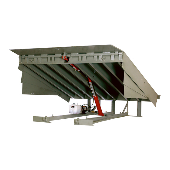
LHP Series
Dock Leveler
Owner's/User's Manual
Poweramp • Division of Systems, LLC • W194 N11481 McCormick Drive • Germantown, WI 53022
800.643.5424 • fax: 262.255.5917 • www.poweramp.com • techservices@poweramp.com
Printed in U.S.A.
Manual No. 4111-0012
© 2018 Systems, LLC - All Rights Reserved
Sept. 2018
Advertisement
Table of Contents

Related Manuals for Poweramp LHP Series


Summary of Contents for Poweramp LHP Series
- Page 1 LHP Series Dock Leveler Owner’s/User’s Manual Poweramp • Division of Systems, LLC • W194 N11481 McCormick Drive • Germantown, WI 53022 800.643.5424 • fax: 262.255.5917 • www.poweramp.com • techservices@poweramp.com Printed in U.S.A. Manual No. 4111-0012 © 2018 Systems, LLC - All Rights Reserved...
-
Page 2: Table Of Contents
Table of Contents Page Precautions Recognize Precautionary Information ..........1 General Operational Precautions ............1 Operational Precautions ..............2 Safety Decals ..................4 Placard ....................5 Owner’s/User’s Responsibilities ............6 Introduction General Information ................8 Component Identification ..............9 Installation Installation Precautions .............. -
Page 3: Precautions
PRECAUTIONS Recognize Precautionary Information General Operational Precautions Safety-Alert Symbol The Safety-Alert Symbol is a graphic representation intended to convey a safety message without the Read and understand the Owner’s/User’s Manual and use of words. When you see this symbol, be alert become thoroughly familiar with the equipment and its to the possibility of death or serious injury. -
Page 4: Operational Precautions
PRECAUTIONS Operational Precautions Learn the safe way to operate this equipment. Read and understand the manufacturer’s instructions. If you have any questions, ask your supervisor. Stay clear of dock leveling device when transport Chock/restrain all transport vehicles. Never vehicle is entering or leaving area. remove the wheel chocks or release the restraining device until loading or unloading is finished, and transport driver has been given... - Page 5 PRECAUTIONS Operational Precautions Do not use dock leveling device if transport vehicle is too high or too low. Do not overload the dock leveling device. Do not operate any equipment while under the influence of alcohol or drugs. Do not leave equipment or material unattended on dock leveling device.
-
Page 6: Safety Decals
1751-0731 Rev A 1751-0731 Serial Tag Left Platform Side File Name: 1751-0731 Rev A Decal Size: 5.05 x 2.40 Right Platform Side Right Platform Side Decal Placement for LHP Series Figure 2 4111-0012 — Sept. 2018 © 2018 Systems, LLC... -
Page 7: Placard
PRECAUTIONS Placard O P E R AT I N G DANGER INSTRUCTIONS POWERED DOCK LEVELERS • Read follow instructions, warnings, and NORMAL OPERATION maintenance schedules in 1. Raise the platform by depressing and the manual and on placards. holding the RAISE button. •... -
Page 8: Owner's/User's Responsibilities
OWNER’S/USER’S RESPONSIBILITIES 1) The manufacturer shall provide to the initial the owner’s/user’s company policies, operating purchaser and make the following information conditions and the manufacturer’s specific readily available to the owners/users and their instructions provided with the dock leveling agents, all necessary information regarding device. - Page 9 OWNER’S/USER’S RESPONSIBILITIES 7) Loading dock safety equipment should never instructions, labels, decals and placards or be used outside of its vertical working range, or their equivalent. Written documentation of outside the manufacturer’s rated capacity. It shall maintenance, replacement parts or damage also be compatible with the loading equipment should be kept.
-
Page 10: Introduction
* CIR (Comparative Industry Rating) To illustrate which connections are to be made in the field at installation, electrical drawings are included Call Poweramp to discuss available voltages, phases with each order or by contacting Systems, LLC and options to meet your specific needs. -
Page 11: Component Identification
INTRODUCTION Component Identification Inspect package and all components. Report any missing or damaged items immediately and note on the shipping Bill Of Lading (BOL). Figure 4 A — Lip D — Powerpack (Motor/Pump/Reservoir) G — Main Frame J — Full Range Toe Guards B —... -
Page 12: Installation
INSTALLATION Installation Precautions It is recommended and good safety practice to use DO NOT connect the dock leveler electrical wiring an additional means to support the dock platform and ground connections until all welding has been and lip anytime when physically working in front of completed. - Page 13 INSTALLATION This page intentionally left blank. 4111-0012 — Sept. 2018 © 2018 Systems, LLC...
-
Page 14: Prepare Pit
INSTALLATION Prepare Pit 10” 14” Figure 5 A—Pit Width B— Dock Floor-to-Pit Floor C— Pit Length D— Pit Corner-to-Corner (Front and Rear) (All Four Corners) (Both Sides of Pit) (Top, Bottom, and Both Sides) Before lowering the dock leveler into the pit, the following must be performed: 1. -
Page 15: Prepare Dock Leveler
INSTALLATION Prepare Dock Leveler Figure 6 A— Lifting Bracket (2 used) B — Shipping Bands Systems, LLC dock levelers are shipped with lifting 3. Attach lifting chains to lifting brackets (A) and to brackets (A) fastened to the platform side joists, a lifting device (i.e., hoist or fork truck) having the and shipping bands (B) around the platform lip and appropriate lifting capacity and reach. -
Page 16: Install Dock Leveler
INSTALLATION Install Dock Leveler Figure 7 Figure 9 Figure 8 A— Distance (Leveler Frame D— Shim Locations (Under H— Rear Hinge Frame Angle L— Distance (Top of Shim Height) Lip Keepers) J— Shims Location(Under Stack-to-Dock Floor) B— Shim Locations (Under E—... - Page 17 INSTALLATION Install Dock Leveler (continued) Shim Stacking Methods Note: Systems, LLC dock levelers are designed with a nominal 1/2” (12.7 mm) shimming distance to allow for pit inconsistencies. 1. Determine height of shim stack (M) for each shim Pyramid Stepped location (B) by performing the following: (Preferred) (Acceptable)
- Page 18 INSTALLATION 3/8 in. 6 in. (9.5 mm) (152 mm) Figure 11 A— Front of Dock Pit C— Side Pit Curb Angle E— Pry Locations G— Rear Pit Curb Angle B— Dock Leveler Frame D— Gap [3/4 in. (19 mm) F— Rear Hinge Frame H—...
- Page 19 INSTALLATION Install Dock Leveler (continued) 12. With the rear hinge frame angle (F) tight against the rear pit curb angle (G), weld the rear hinge frame angle (F) to the rear pit curb angle (G) using a 3/8 in. DO NOT weld continuously along the full length (9.5 mm) flare bevel skip weld —...
- Page 20 INSTALLATION Figure 12 A — Platform Joists D — Maintenance Prop B — Shim Location (Under Platform Cylinder Trunnions) E — Shim Location (Under Maintenance Prop) C — Removable “Clean Sweep” Frame Section 17. Shim and weld the maintenance prop: 18.
- Page 21 INSTALLATION Install Dock Leveler (continued) Shim Stacking Methods 20. Remove the Shipping Bar (C) by grinding the tack welds that hold it in place during transport. Pyramid Stepped LH models are shipped with a front frame section (Preferred) (Acceptable) (C) installed. This temporary frame holds the leveler frame at the correct dimensions until the leveler is permanently anchored into place.
-
Page 22: Install Control Panel And Wiring
INSTALLATION Install Control Panel and Wiring Where indicated, all components must be connected Make sure that the power source has been locked to a SAFETY EARTH GROUND that conforms to out and tagged according to OSHA regulations and the 1999 National Electrical Code Section 250-50 approved local electrical codes. - Page 23 INSTALLATION Danfoss Control Panel Wiring (1-Phase) Jumper wire (L1 to 95) Jumper wire (A1 to L2) Voltage Motor FLA 115V 13.8A 208V 6.9A 230V 6.9A Note: All Danfoss control boxes require jumper wires shown to be added for push button to function. Danfoss Control Panel Wiring (3-Phase) Jumper wire (L1 to 95)
- Page 24 INSTALLATION Placard Installation Instructions Placard Installation Instructions • Owner/Users are responsible for the installation and placement of product • Owner/Users are responsible for the installation and placement of product • Owner/Users are responsible for the installation and placement of product placards.
- Page 25 INSTALLATION This page intentionally left blank. 4111-0012 — Sept. 2018 © 2018 Systems, LLC...
-
Page 26: Put New Dock Leveler Into Service
INSTALLATION Put New Dock Leveler Into Service Note: For dock levelers equipped with the Auto Return To Dock (ARTD), the platform will automatically return to the cross-traffic position if A hard hat or other applicable head protection the ARTD is enabled. When the platform is at the should always be worn when working under or full below-dock position, there is a six-second delay around a dock leveler. -
Page 27: Operation
OPERATION Operational Precautions Stay clear of dock leveler and vehicle restraint 12 in. (305 mm) when transport vehicle is entering or leaving dock area. DO NOT move or use the dock leveler or restraint if 12 in. (305 mm) anyone is under or in front of leveler. Keep hands and feet clear of pinch points. -
Page 28: Operating Instructions
OPERATION Operating Instructions Ramp Loading/Unloading 1. Check to make sure the transport vehicle is positioned squarely against dock bumpers. 2. Instruct driver to remain at the dock until the loading or unloading process has been completed. 3. Chock the transport vehicle wheels, or use a vehicle restraint if available. -
Page 29: Optional Equipment
OPERATION Operating Instructions (continued) End Loading/Unloading Note: When end unloading is finished and access to the rest of the transport vehicles is still required, 1. Check to make sure the transport vehicle is the platform lip will need to be extended. See Ramp positioned squarely against dock bumpers. -
Page 30: Maintenance
MAINTENANCE Maintenance Precautions Figure 22 Figure 20 Figure 21 A— Tag Out Device B —Lock Out Device C — Maintenance Prop D— Header When working with electrical or electronic controls, make sure that the power source has been tagged (A) and locked out (B) according to OSHA regulations * Unless the dock leveler is equipped with a tethered and approved local electrical codes (see Figure 21). - Page 31 MAINTENANCE This page intentionally left blank. 4111-0012 — Sept. 2018 © 2018 Systems, LLC...
-
Page 32: Periodic Maintenance
MAINTENANCE Periodic Maintenance Figure 23 A— Lip Area C— Main Cylinder Pins B— Platform Hinge Area D— Lip Cylinder Pins To ensure normal operation of the dock leveler, use only aircraft hydraulic fluid designed to meet or exceed Weekly Maintenance military specification MIL-H-5606-G. - Page 33 MAINTENANCE Quarterly Maintenance • Complete Weekly Maintenance. 3 in. • Inspect the following for damage/abnormal wear: • Check welds for cracks. • Cylinder pins and mounting holes. • Lip hinge pins and rear hinge pins. • Check full range toe guards (if equipped) for free movement.
-
Page 34: Adjustments
ADJUSTMENTS Adjust Main Pressure Relief Unless the dock leveler is equipped with a tethered remote, two people are required to engage the maintenance prop: one person to operate the unit, the other person to engage the maintenance prop. In addition, it is recommended and good safety practice to use an additional means to support the dock platform and lip anytime when physically working in front of or under the dock leveler. -
Page 35: Adjust Lip Function
ADJUSTMENTS Adjust Lip Function 5. Adjust hex adjusting screw (B) as follows: • If the lip opens as the platform begins to rise, turn sequence valve clockwise in 1/4 turn adjustments until operation is satisfactory. • If the lip will not fully retract when the platform returns to the stored position, turn sequence valve counterclockwise in 1/4 turn increments. -
Page 36: Troubleshooting
TROUBLESHOOTING Unless the dock leveler is equipped with a tethered When service under the dock leveler is required, remote, two people are required to engage the always lock all electrical disconnects in the OFF maintenance prop: one person to operate the unit, position after raising the platform and engaging the the other person to engage the maintenance prop. - Page 37 TROUBLESHOOTING Symptom Possible Cause Solution Check for blown fuses at branch circuit disconnect. Replace fuse. Determine cause of blown fuse. Check motor starter as follows: 1. Disconnect wires at load side of starter. 2. Energize the starter. No voltage is present on 3.
- Page 38 TROUBLESHOOTING Symptom Possible Cause Solution Add fluid, see pages 30-31 for proper fluid level and Low hydraulic fluid. type. Clean and inspect valves. Flush contaminated oil Contaminated hydraulic from hydraulic system. Fill system with new oil. See system. pages 30-31. Platform rises slowly.
- Page 39 TROUBLESHOOTING Symptom Possible Cause Solution Lip does not stay extended when leveler Faulty lip cylinder. Replace lip cylinder. lowers. Platform DOES rise to full height, but lip DOES Sequence Valve requires Adjust valve as necessary. See page 33 for NOT extend or extend adjustment.
-
Page 40: Parts
PARTS Danfoss Control Box Part Number Voltage Phase Description 7141-0268 110v 1-Phase Danfoss Control Box (MTR 3627A) 7141-0269 230v 1-Phase Danfoss Control Box (MTR 3627C) 7141-0270 230v 3-Phase Danfoss Control Box (MTR 3627E) 7141-0271 460v 3-Phase Danfoss Control Box (MTR 3627F) * Provide dock leveler serial number, voltage, phase, and options when e-mailing, calling or faxing controller orders 4111-0012 —... -
Page 41: Optional Electrical Parts (Control Box)
PARTS Optional Electrical Parts (Control Box) Part Number Description Control Box w/Optional Equipment * Provide dock leveler serial number, voltage, phase, and options when e-mailing, calling or faxing controller orders 4111-0012 — Sept. 2018 © 2018 Systems, LLC... -
Page 42: Lip And Platform Parts
PARTS Lip and Platform Parts 4111-0012 — Sept. 2018 © 2018 Systems, LLC... - Page 43 PARTS Lip and Platform Parts LIPS ITEM QTY 25K CAPACITY 35K CAPACITY 40K CAPACITY 6.0 FOOT WIDTH 16” DLIP-1250 DLIP-1256 DLIP-1259 18” DLIP-1251 DLIP-1257 DLIP-1260 20” DLIP-1252 DLIP-1258 DLIP-1261 6.5 FOOT WIDTH 16” DLIP-1262 DLIP-1268 DLIP-1271 18” DLIP-1263 DLIP-1269 DLIP-1272 20”...
-
Page 44: Hydraulic Components
PARTS Hydraulic Components 4111-0012 — Sept. 2018 © 2018 Systems, LLC... - Page 45 PARTS Hydraulic Components Item Quantity Part Number Description DOTH-2852 Cylinder, Lip, 2” Bore x 6” Stroke 0521-0211 Cylinder, Main Hoist, 2.5” Bore x 14” Stroke DOTH-2814 Breather, Vent Plug, 3/8” Male - NPT DOTH-2792 Hose Assembly, Main, 1/4 x 30 OL (R-S) DOTH-2798 Hose Assembly, Lip, 1/4 x 70 OL (R-S) DOTH-2771...
-
Page 46: Weather Seals
PARTS Weather Seals Weather Seal Kits Item Quantity Part Number Description 0195-0021 Brush Kit (Includes Seal and Track), 1-1/2 in. 82" Lg. (Both Sides) 0195-0033 Rubber Kit (Includes Seal and Track), 1-1/2 in. 82" Lg. (Both Sides) Individual Replacement Seals Item Quantity Part Number... - Page 47 PARTS This page intentionally left blank. 4111-0012 — Sept. 2018 © 2018 Systems, LLC...
-
Page 48: Toe Guards
PARTS Toe Guards Item Quantity Part Number Description DKIT-9179 Toe Guard Kit, Sliding 6’ (Includes Both Sides) DKIT-9180 Toe Guard Kit, Sliding 8’ (Includes Both Sides) DKIT-9181 Toe Guard Kit, Sliding 10’ (Includes Both Sides) 0011-0052 Toe Guard, Middle (6 Foot) 0011-0054 Toe Guard, Middle (8 Foot) 0011-0056... - Page 49 PARTS This page intentionally left blank. 4111-0012 — Sept. 2018 © 2018 Systems, LLC...
-
Page 50: Miscellaneous
MISCELLANEOUS This page intentionally left blank. 4111-0012 — Sept. 2018 © 2018 Systems, LLC... -
Page 51: Customer Information
MISCELLANEOUS Customer Information Figure 28 Figure 27 NOTE: Refer to Figure 27 for left/right orientation of dock Dock Leveler Information leveler and Figure 28 for example of decal. The LEVELER model/serial number decal is Model ___________________________________ located on the left platform joist near the front (lip) of dock leveler (A). -
Page 52: Warranty
STANDARD PRODUCT WARRANTY SYSTEMS, LLC warrants that its products will be free from defects in design, materials and workmanship for a period of one (1) year from the date of shipment. All claims for breach of this warranty must be made within 30 days after the defect is or can with reasonable care, be detected.
Need help?
Do you have a question about the LHP Series and is the answer not in the manual?
Questions and answers