Table of Contents
Advertisement
Quick Links
Advertisement
Table of Contents
Troubleshooting

Related Manuals for Miller ProHeat 35 CE


Summary of Contents for Miller ProHeat 35 CE
- Page 1 OM-271146T 2022-03 Processes Induction Heating Description Induction Heating Power Source ProHeat 35 ™ CE And Non CE Models (For Stock Nos. 907689, and 907690) For product information, Owner’s Manual translations, and more, visit www.MillerWelds.com...
- Page 2 We know you don’t have time to do it any other way. That’s why when Niels Miller first started building arc welders in 1929, he made sure his products offered long-lasting value and superior quality.
-
Page 3: Table Of Contents
TABLE OF CONTENTS SECTION 1 − SAFETY PRECAUTIONS − READ BEFORE USING ....... . . 1-1. - Page 4 TABLE OF CONTENTS SECTION 7 − SETUP AND OPERATION ............7-4-1.
- Page 5 DECLARATION OF CONFORMITY for European Community (CE marked) products. MILLER Electric Mfg. LLC, 1635 West Spencer Street, Appleton, WI 54914 U.S.A. declares that the product(s) identified in this declaration, when used exclusively with MILLER induction heating cables and inductors, conform to the essential requirements and provisions of the stated Council Directive(s), Commission Regulation(s) and Standard(s).
- Page 6 DECLARATION OF CONFORMITY For United Kingdom (UKCA marked) products. MILLER Electric Mfg. LLC, 1635 West Spencer Street, Appleton, WI 54914 U.S.A. declares that the product(s) identified in this declaration, when used exclusively with MILLER induction heating cables and inductors, conform to the essential requirements and provisions of the stated Regulation(s) and Standard(s).
- Page 7 EMF DATA SHEET FOR INDUCTION HEATING POWER SOURCE MILLER Electric Mfg. Co., 1635 Spencer Street, Appleton, WI 54914 U.S.A. is voluntarily providing the following infor mation to assist European employers in carrying out their assessments to show compliance with Directive 2013/35/EU on the minimum health and safety requirements regarding the exposure of workers to the risks arising from physical agents (electromagnetic fields).
-
Page 9: Section 1 − Safety Precautions − Read Before Using
SECTION 1 − SAFETY PRECAUTIONS − READ BEFORE USING ihom _2022-01 Protect yourself and others from injury — read, follow, and save these important safety precautions and operating instructions. 1-1. Symbol Usage DANGER! − Indicates a hazardous situation which, if Indicates special instructions. -
Page 10: Additional Hazards For Installation, Operation, And Maintenance
FIRE OR EXPLOSION hazard. INDUCTION HEATING can burn. D Do not overheat parts. D Do not touch hot parts bare-handed. D Watch for fire; keep extinguisher nearby. D Allow cooling period before handling parts or equipment. D Keep flammables away from work area. Do not touch or handle induction head/coil during operation un- Do not locate unit on, over, or near combustible surfaces. -
Page 11: California Proposition 65 Warnings
For additional information on induction heating and EMF exposure, see following procedures in order to minimize exposure to EMF fields from the bulletin at this location: the welding circuit: https://www.millerwelds.com/−/media/miller−electric/files/pdf/safety/ bulletins/bulletin−on−induction−heating−and−emf−exposure.pdf 1. Keep cables close together by twisting or taping them, or using a About Implanted Medical Devices: cable cover. -
Page 12: Section 2 − Consignes De Sécurité − Lire Avant Utilisation
SECTION 2 − CONSIGNES DE SÉCURITÉ − LIRE AVANT UTILISATION ihom_2022-01_fre Pour écarter les risques de blessure pour vous−même et pour autrui — lire, appliquer et ranger en lieu sûr ces consignes relatives aux précautions de sécurité et au mode opératoire. 2-1. -
Page 13: Symboles De Dangers Supplémentaires En Relation Avec L'installation
chauffage peuvent déplacer l’air, abaisser le niveau d’oxygène et Une fois le travail achevé, assurez−vous qu’il ne reste aucune trace provoquer des lésions ou des accidents mortels. S’assurer que l’air d’étincelles incandescentes ni de flammes. ambiant ne présente aucun danger. Utiliser exclusivement des fusibles ou coupe−circuits appropriés. -
Page 14: Proposition Californienne 65 Avertissements
Tous les soudeurs doivent appliquer les procédures suivantes pour se reporter au communiqué suivant: minimiser l’exposition aux CEM provenant du circuit de soudage: https://www.millerwelds.com/−/media/miller−electric/files/pdf/safety/ 1. Rassembler les câbles en les torsadant ou en les attachant avec bulletins/bulletin−on−induction_heating−and−emf−exposure−fr.pdf du ruban adhésif ou avec une housse. -
Page 15: Section 3 − Definitions
SECTION 3 − DEFINITIONS 3-1. Additional Safety Symbols And Definitions Some symbols are found only on CE products. Warning! Watch Out! There are possible hazards as shown by the symbols. Safe1 2012−05 Wear dry insulating gloves. Do not wear wet or damaged gloves. Safe56 2017−04 Disconnect input plug or power before working on machine. - Page 16 Keep your head out of the fumes. Safe80 2017−04 Use forced ventilation or local exhaust to remove the fumes. Safe81 2012−07 Use ventilating fan to remove fumes. Safe82 2012−07 Always wear safety glasses or goggles during and around heating operations to prevent possible injury. Safe83 2012−07 Wear either safety glasses or full goggles depending on type of operation and nearby processes.
-
Page 17: Miscellaneous Symbols And Definitions
Hazardous voltage remains on input capacitors after power is turned off. Do not touch fully charged capacitors. Always wait 60 seconds after power is turned off before working on unit, AND check input ca- pacitor voltage, and be sure it is near 0 before touching any parts. >... -
Page 18: Section 4 − Specifications
4-3. Information About Default Weld Parameters And Settings NOTICE − Each welding application is unique. Although certain Miller Electric products are designed to determine and default to certain typical welding parameters and settings based upon specific and relatively limited application variables input by the end user, such default settings are for reference purposes only;... - Page 19 C. EU Ecodesign Information Do not discard product (where applicable) with general waste. Reuse or recycle Waste Electrical and Electronic Equipment (WEEE) by disposing at a designated collection facility. Contact your local recycling office or your local distributor for further information. Critical raw materials possibly present in indicative amounts higher than 1 gram at component level Component Critical Raw Material...
- Page 20 Ç Ç Ç Ç Ç Ç Ç Ç Ç Ç Ç Ç Ç Ç Ç Ç Ç NOTICE − The Miller ProHeat 35 Rolling Inductor is rated for operation between 14° F and 140° F (−10° C to 60° C). For operation at -40° F to 14°...
-
Page 21: Section 5 − Installation
SECTION 5 − INSTALLATION 5-1. Selecting A Location Do not move or operate unit Movement where it could tip. Location And Airflow Special installation may be required where gasoline or volatile liquids are present − see NEC Article 511 or CEC Section 20. -
Page 22: Electrical Service Guide
5-3. Electrical Service Guide Elec Serv 2020-02 CE-marked equipment shall only be used on a supply network that is a three-phase, four-wire system with an earthed neutral. Failure to follow these electrical service guide recommendations could create an electric shock or fire hazard. These recommendations are for a dedicated circuit sized for the rated output and duty cycle of the welding power source. -
Page 23: Connecting 3-Phase Input Power For 460/575 Volt Models
5-4. Connecting 3-Phase Input Power For 460/575 Volt Models GND/PE Earth Ground Tools Needed: 3/8 in. input3 2015−01 / 803994-E OM-271146 Page 15... - Page 24 5-4. Connecting 3-Phase Input Power For 460/575 Volt Models (continued) age available at site. Connect input conductors L1, L2 and L3 to Installation must meet all National welding power source line terminals. and Local Codes − have only qualified Input Power Conductors (Customer persons make this installation.
-
Page 25: Connecting 3-Phase Input Power For 400/460 Volt Iec And Ce Models
5-5. Connecting 3-Phase Input Power For 400/460 Volt IEC And CE Models GND/PE Earth Ground Tools Needed: 3/8 in. 5/32 in. Input3 2015-01 / 272715-A OM-271146 Page 17... -
Page 26: Coolant Jumper Connections
5-5. Connecting 3-Phase Input Power For 400/460 Volt IEC And CE Models (continued) age available at site. Connect input conductors L1, L2 and L3 to Installation must meet all National welding power source line terminals. and Local Codes − have only qualified Input Power Conductors (Customer persons make this installation. -
Page 27: Power Source Output Connections
Extension cables must be the same Do not move or disconnect cables length: 25 ft (7.6 m), 50 ft (15.2 m), or NOTICE − Use only Miller ProHeat acces- while output is on. 75 ft (22.8 m). sories with a Miller ProHeat power source. -
Page 28: Remote 14 Receptacle Rc14 Information And Connections
Remote 14 Receptacle RC14 (See Section 5-9) To connect to receptacle, align key- way, insert plug and tighten threaded collar. NOTICE − Use only Miller ProHeat accessories with a Miller ProHeat power source. C L N 803993-D 5-9. Remote 14 Socket Information... -
Page 29: Temperature Recorder Receptacle Rc9 Information And Connections
5-10. Temperature Recorder Receptacle RC9 Information And Connections Plug Threaded Collar Temperature Recorder Receptacle RC9 (See Section 5-11) To connect to receptacle, insert plug and tighten threaded collar. 803993-D 5-11. Temperature Recorder Socket Information Socket No. Socket Information Thermocouple No. 1 (TC1), 0-10 volt DC signal [0V = −50°F (−46° C), 10V = 1500°F (816°C)] Thermocouple No. -
Page 30: Secondary Insulation Protection
5-12. Secondary Insulation Protection Connect supplied ground lead(s) between workpiece and power source to provide proper secondary insulation protection. For single output, only one ground lead is required. For dual output , use both ground leads. Secondary insulation protection circuitry automatically shuts down the power source output if a potentially hazardous... -
Page 31: 115 Volt Ac Duplex Receptacle And Supplementary Protector
5-13. 115 Volt AC Duplex Receptacle And Supplementary Protector 115 VAC 2.5 A Single-Phase AC Receptacle RC1 Supplementary Protector CB1 (2.5 A) The receptacle supplies nominal 115 volts AC auxiliary power for use with the optional digital recorder. Maxi- mum output from receptacle is 2.5 amperes. - Page 32 The following describes the thermocouple routing from work to power source. Type K thermocouple wire (two wire) is attached directly to the workpiece using a Thermocouple Attachment Unit (see next section for information on attaching thermocouples). The other end is fitted with a 2-pin type K connector. The 2-pin connector plugs into the 3-pin composite extension cable.
-
Page 33: Attaching Welded Thermocouples
5-15. Attaching Welded Thermocouples Do NOT weld thermocouples while connected to power source. Attach thermocouples using a portable Thermocouple Attachment Unit (TAU). This unit spot welds thermocouple wire directly to the workpiece. This method of thermocouple attachment ensures accurate temperature measurement. Clean (file or grind) any loose scale or rust from the workpiece at the places where the wires will be attached. -
Page 34: Using Contact Thermocouple Sensors
5-16. Using Contact Thermocouple Sensors Blanket Contact Thermocouple Sensor (See Product Literature Sheet) The welded thermocouples discussed previously can be used for preheating or stress relieving. Welded thermo- couples are normally used in stress relieving applications because of their accuracy and ability to withstand high temperatures. -
Page 35: Section 6 − Components And Controls
SECTION 6 − COMPONENTS AND CONTROLS 6-1. Controls 803995-B LED lights to indicate a system limit 14 Parameter Button When a control panel button is pushed condition. the yellow lamp lights to indicate ac- Use button to display real time power Heat On LED tivation. -
Page 36: Section 7 − Setup And Operation
SECTION 7 − SETUP AND OPERATION 7-1. Safety Equipment Do not wear rings or watches during operation. Wear following during operation: Dry, Insulating Gloves Safety Glasses With Side Shields sb3.1* 1/94 7-2. System Description The ProHeat 35 Induction Heating Power Source is designed to function either as an air-cooled system or a liquid-cooled system. Depending on the system type (including Air-cooled, Liquid-cooled, and Rolling Inductor), the power source is automatically configured to operate and provide an output appropriate for the type of connected heating device. - Page 37 Possible selections: Degree Units: °F / °C Tolerance: ±5 to 99 in °F (±3 to 55 in °C) Control Mode: Temp / Remote / Time / Manual Temperature Mode S Initial kW value used in Rolling Inductor mode only S Uses IR to control power Time Mode S Does not use Initial kW setting S IR sensors can monitor temperature but not control power...
- Page 38 Set proper scaling for IR Sensor. Miller has supplied two different sensors for the Rolling Inductor. The scaling must be set correctly to display the proper temperatures on the temperature display. Present Sensor Original Sensor Part Number 283080 265076 IR Input Max 752°F (400°C)
-
Page 39: Factory Defaults
7-4-1. Factory Defaults To reset the system back to factory default settings, turn off the power source, and wait until the display goes blank. Turn on the power source. When the display lights, press and hold the Increase and Decrease buttons. - Page 40 7-5-1-2. Bake-Out The bake-out process allows the operator to program a temperature and soak time as well as a cooling rate from bake-out if desired. When this process is selected, the following screen appears on the display: Bake-Out Screen Mode..: Bake−Out Control TC:>1 Soak Temp.: Soak Time: 01:00:00...
- Page 41 The default position of the cursor is next to Control TC. Press the Increase or Decrease button to select the number of control thermocouples to be used for the program. Selections are as follows: 1, 1,2, 1,2,3, or 1,2,3,4. TC1 MUST always be a control thermocouple. TC2 thru TC4 can be used for controlling or monitoring.
- Page 42 7-5-1-4. PWHT Operation When a PWHT cycle is started, you may monitor where you are at in the cycle by selecting the Status Screen. From there you can determine what mode you are in, what the heat controller’s current calculated target temperature is, and see the Soak Timer Countdown. When using a single TC in the control loop, it is in control of the entire cycle.
- Page 43 7-5-1-5. Custom Program In Custom Program, the operator can create a custom program with multiple steps or nonsymmetrical heat treat programs where the heating and cooling rates and temperatures are different. When this process is selected, the following screen appears on the display: This is the screen for initial use of the system.
- Page 44 Ramp Function When type is set to Ramp, the following screen appears on the display: Custom Program Screen Mode..: Custom Program Segment..: Type..: Ramp 600 _/Hr Temperature: Ramp Rate: Use the Cursor button to move the cursor to the Temperature or Ramp Rate position and use the Increase or Decrease button to set the desired value.
- Page 45 The only changeable parameter in the End segment is selecting the number of thermocouples. Use the Cursor button to move the cursor to the Control TC position. Press the Increase or Decrease button to select the number of control thermocouples to be used for the program.
-
Page 46: Remote Control
Custom Program Screen Mode..: Custom Program Segment..: Type..: End Control TC.: 1 End segment ends the heat treat cycle. Controller is programmed to control the process using four thermocouples. 7-5-2. Remote Control Remote Control operates the system from a remote device which energizes or de−energizes output as well as setting the desired output power level as a function of the maximum output power setting in the system setup screen. -
Page 47: Manual Control
7-5-4. Manual Control Manual control allows programming of a specific power level for a specific period of time. When this process is selected, the following screen appears on the display: Manual Program Screen Mode..: Manual Power..: 0.0 KW Command.: 0.0 KW Current: Run Time: 00:03:00 Voltage:... - Page 48 To view the System Setup screen, simultaneously press the Parameters and Program buttons and the following screen will appear on the display: Press Cursor button to move cursor to the parameter to change. Press Increase or Decrease button to set parameters.
-
Page 49: Run Status
Press Program button once to enter the Rolling Inductor Program screen. The screen should look as shown below. Rolling Inductor Program Screen Mode..: Manual Power…: 0.0 KW Command.: >0.0 KW Current: 0 A Run Time: 00:03:00 Voltage: 0 V Frequency: 4.5 kHz Plug one end of the thermocouple extension cable into TC5 on the power source and the other end into the back of the Rolling Inductor. -
Page 50: Manual Control
7-6-2. Manual Control Run Status Screen Mode..: Manual TC5: Power..: 0.0 KW TC6: Countdown: −−:−−:−− TvlIPM(Off): Status...: Stopped During active operation, Power shows the actual power delivered from the power source, Countdown shows the time remaining in the heating cycle, and Status indicates if the system is running or stopped. -
Page 51: Cooler
Firmware Revision X.XX Copyright (c) 2005 − 2015 Miller Electric Mfg. Co. X.XX indicates the firmware revision number installed in the unit. If an error is detected during the check routine, the system fault LED illuminates and an error message screen appears on the display (see Section 10-5). - Page 52 The Stop button indicator LED illuminates to indicate no heating cycle is in process. The temperature displays indicate actual temperature from the TC’s (thermocouples). If no thermocouples are connected, the displays indicate OPEN. Control LEDs illuminate to indicate the number of control TC’s in the last program. The appropriate degree units (°F or °C) light illuminates.
- Page 53 To make changes to a program while in run mode, press the Hold button and the yellow indicator LED will illuminate, and the Run button yellow indicator LED will turn off. When in hold, the system will maintain the actual temperature of the hottest thermocouple while the program is being changed. Press the Program button and the yellow indicator LED will illuminate.
-
Page 54: System Operating Characteristics
7-10. System Operating Characteristics The power source delivers a high-frequency alternating current output that energizes the coil creating the magnetic field used to heat the workpiece. The power source output characteristics are a function of the configuration, type and number of coils used as shown in the following table: Table 7-1. - Page 55 Table 7-2. Rolling Inductor Output Characteristics Output Type Maximum Amperage Single Rolling Inductor 300 A 300 A Per Output Dual Rolling Inductor The system maximum power is 35 kW, so each output will have approximately 17.5 kW, which uses less than 300 A The Rolling Inductor can be operated Max Power Output Vs.
-
Page 56: Section 8 − Maintenance
SECTION 8 − MAINTENANCE 8-1. Routine Maintenance Disconnect power Maintain more often before maintaining. during severe conditions. n = Check Z = Change ~ = Clean l = Replace Reference * To be done by Factory Authorized Service Agent Daily n Visually inspect condi- tion of cords and cables. -
Page 57: Calibration Verification Equipment
Calibration Label Suggested connector from Fluke item 80CK−M or equivalent. Suggested label from Q−CEES item MILLER Part No. 300168 can be used to QCC306BU or equivalent. A length of type K thermocouple wire is connect the Recorder to the DC power required. -
Page 58: Finishing Procedure
8-3-3. Finishing Procedure If ProHeat 35 was set for Temp in Control Mode follow steps 8-3-1, steps 4.−6. to change it back to Temp. Turn ProHeat 35 power switch off. Have qualified person disconnect primary power. Remove precision DVM and TC calibrator. Complete calibration label &... - Page 59 OM-271146 Page 51...
- Page 60 OM-271146 Page 52...
-
Page 61: Section 9 − Safety Precautions For Servicing
SECTION 9 − SAFETY PRECAUTIONS FOR SERVICING Protect yourself and others from injury — read, follow, and save these important safety precautions and operating instructions. 9-1. Symbol Usage safety_ihtm 2022-01 DANGER! − Indicates a hazardous situation which, if Indicates special instructions. not avoided, will result in death or serious injury. -
Page 62: California Proposition 65 Warnings
For additional information on induction heating and EMF exposure, see the bulletin at this location: https://www.millerwelds.com/−/media/miller−electric/files/pdf/safety/ 1. Keep cables close together by twisting or taping them, or using a bulletins/bulletin−on−induction−heating−and−emf−exposure.pdf cable cover. About Implanted Medical Devices: Implanted Medical Device wearers should consult their doctor and the 2. -
Page 63: Section 10 − Diagnostics & Troubleshooting
SECTION 10 − DIAGNOSTICS & TROUBLESHOOTING The ProHeat 35 power source has on-board capabilities to aid in troubleshooting problems should any conditions occur during operation. This troubleshooting capability consists of the Fault LED, Limit LED, and message screens that appear on the front panel LCD display. 10-1. -
Page 64: Limit Conditions
10-2. Limit Conditions A limit condition indicates that the system has encountered an open thermocouple or is outside the range of its optimum operating conditions or parameters. Should a limit condition occur during operation, the yellow Limit LED will flash to indicate a problem. If the active screen on the LCD display is Run Status or Parameters, a message describing the particular limit condition will appear on the display. -
Page 65: Fault Conditions
Limit Condition Additional Information L11: Coolant Overtemp Limit Check coolant flow and level Clean coolant filters and heat exchanger Increase number of turns Verify appropriate insulation thickness L12: Power Source Overtemp Limit Check for blocked vents Clean wind tunnel heat sinks L13: Cable Connection Check for loose/open output connection Verify all output cables are same type... - Page 66 Fault Condition Additional Information F62: Isolation Fault Check for exposed conductor or for moisture on blanket Using conductive coolant in cooler (043810 low conductivity coolant is recommend). F63: Line Voltage Fault Check line voltage Check voltage values on diagnostic screen DIAG2 (see Section 10-7) F64: Power Source Overtemp Fault Verify power source vents and wind tunnel are unobstructed...
-
Page 67: Infrared Sensor Troubleshooting Guide
10-6. Infrared Sensor Troubleshooting Guide Problem Cause Potential Solution Infrared sensor is connected but Verify settings on ProHeat are set for IR 4−20 mA, and temp range is temperature is not in range. set to 212°F−752°F (100°C−400°C) if infrared sensor is attached. Verify settings on ProHeat are set for K TC if thermocouple measuring device is attached. - Page 68 Cable 2 − This is the cable type hooked up to output number two. Possible labels: AIR − for an air-cooled cable LQD − for a liquid-cooled cable PLUG − for a protective plug OPEN − no cable or plug in place ROLL −...
-
Page 69: Proheat 35 Firmware Versions And Compatibility
If possible, verify firmware revision levels prior to ordering circuit boards. If firmware revisions cannot be verified, contact Miller Service for instructions on updating firmware. All boards are compatible with firmware updates so the part number on old boards does not indicate firmware revision. -
Page 70: Measuring/Discharging Input Capacitor Voltage Before Working On Unit
10-9. Measuring/Discharging Input Capacitor Voltage Before Working On Unit Turn Off welding power source, disconnect input power. Significant DC voltage can Tools Needed: remain on capacitors after unit is Off. Always check the 5/16, 3/8 in. voltage as shown to be sure the input capacitors have discharged before working on unit. -
Page 71: Blowing Out Inside Of Unit
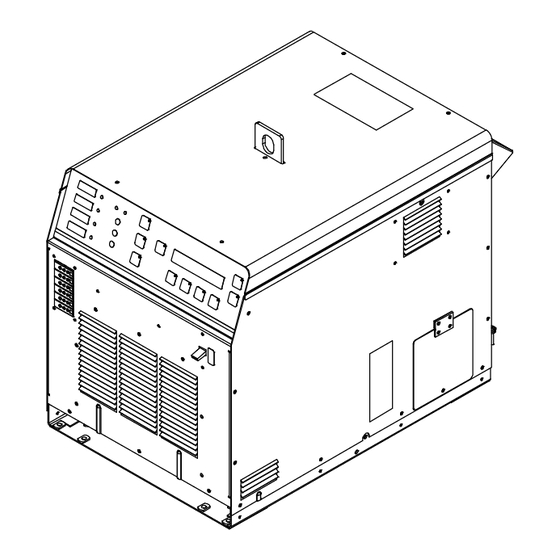
10-10. Blowing Out Inside Of Unit Do not remove case when blowing out inside of unit. To blow out unit, direct airflow through front and back louvers as shown. Ref. 803992-B Notes MATERIAL THICKNESS REFERENCE CHART 24 Gauge (.025 in.) 22 Gauge (.031 in.) 20 Gauge (.037 in.) 18 Gauge (.050 in.) -
Page 72: Section 11 − Electrical Diagram
SECTION 11 − ELECTRICAL DIAGRAM Figure 11-1. Circuit Diagram OM-271146 Page 64... - Page 73 271167-B OM-271146 Page 65...
- Page 74 Notes Work like a Pro! Pros weld and cut safely. Read the safety rules at the beginning of this manual.
- Page 75 Effective January 1, 2022 (Equipment with a serial number preface of NC or newer) This limited warranty supersedes all previous Miller warranties and is exclusive with no other guarantees or warranties expressed or implied. LIMITED WARRANTY − Subject to the terms and conditions...
- Page 76 Contact the Delivering Carrier to: File a claim for loss or damage during shipment. For assistance in filing or settling claims, contact your distributor and/or equipment manufacturer’s Transportation Department. © ORIGINAL INSTRUCTIONS − PRINTED IN USA 2022 Miller Electric Mfg. LLC 2022−01...
Need help?
Do you have a question about the ProHeat 35 CE and is the answer not in the manual?
Questions and answers