Table of Contents
Advertisement
Quick Links
Advertisement
Table of Contents
Troubleshooting

Subscribe to Our Youtube Channel
Related Manuals for Miller 907689


Summary of Contents for Miller 907689
- Page 1 OM-271146J 2018-06 Processes Induction Heating Description Induction Heating Power Source ProHeat 35 ™ CE And Non CE Models (For Stock Nos. 907689, and 907690) For product information, File: Induction Heating Owner’s Manual translations, and more, visit www.MillerWelds.com...
- Page 2 We know you don’t have time to do it any other way. That’s why when Niels Miller first started building arc welders in 1929, he made sure his products offered long-lasting value and superior quality.
-
Page 3: Table Of Contents
TABLE OF CONTENTS SECTION 1 − SAFETY PRECAUTIONS − READ BEFORE USING ....... . . 1-1. - Page 4 TABLE OF CONTENTS SECTION 7 − SETUP AND OPERATION ............7-5-2.
- Page 5 DECLARATION OF CONFORMITY for European Community (CE marked) products. MILLER Electric Mfg. Co., 1635 Spencer Street, Appleton, WI 54914 U.S.A. declares that the product(s) identified in this declaration conform to the essential requirements and provisions of the stated Council Directive(s) and Standard(s).
- Page 6 EMF DATA SHEET FOR INDUCTION HEATING POWER SOURCE MILLER Electric Mfg. Co., 1635 Spencer Street, Appleton, WI 54914 U.S.A. is voluntarily providing the following infor mation to assist European employers in carrying out their assessments to show compliance with Directive 2013/35/EU on the minimum health and safety requirements regarding the exposure of workers to the risks arising from physical agents (electromagnetic fields).
-
Page 7: Section 1 − Safety Precautions − Read Before Using
SECTION 1 − SAFETY PRECAUTIONS − READ BEFORE USING ihom _2018-01 Protect yourself and others from injury — read, follow, and save these important safety precautions and operating instructions. 1-1. Symbol Usage DANGER! − Indicates a hazardous situation which, if Indicates special instructions. -
Page 8: Additional Symbols For Installation, Operation, And Maintenance
FIRE OR EXPLOSION hazard. INDUCTION HEATING can burn. D Do not overheat parts. D Do not touch hot parts bare-handed. D Watch for fire; keep extinguisher nearby. D Allow cooling period before handling parts or equipment. D Keep flammables away from work area. Do not touch or handle induction head/coil during operation un- Do not locate unit on, over, or near combustible surfaces. -
Page 9: California Proposition 65 Warnings
READ INSTRUCTIONS. H.F. RADIATION can cause interference. D High-frequency (H.F.) can interfere with radio D Read and follow all labels and the Owner’s navigation, safety services, computers, and Manual carefully before installing, operating, or communications equipment. servicing unit. Read the safety information at the beginning of the manual and in each D Have only qualified person familiar with elec- section. -
Page 10: Section 2 − Consignes De Sécurité − Lire Avant Utilisation
SECTION 2 − CONSIGNES DE SÉCURITÉ − LIRE AVANT UTILISATION ihom_2018−01_fre Pour écarter les risques de blessure pour vous−même et pour autrui — lire, appliquer et ranger en lieu sûr ces consignes relatives aux précautions de sécurité et au mode opératoire. 2-1. -
Page 11: Dangers Supplémentaires En Relation Avec L'installation, Le Fonctionnement Et La Maintenance
Si la ventilation est médiocre, porter un respirateur anti-vapeurs ap- Ne pas couvrir les protections isolantes refroidies par air avec un prouvé. matériau pouvant entraîner leur surchauffe. Lire et comprendre les fiches de données de sécurité et les instructions Ne pas souder là où l’air ambiant pourrait contenir des poussières, du fabricant concernant les adhésifs, les revêtements, les nettoyants, gaz ou émanations inflammables (vapeur d’essence, par exemple). -
Page 12: Proposition Californienne 65 Avertissements
Demander seulement à des personnes qualifiées familiarisées avec L’EMPLOI EXCESSIF peut SUR- des équipements électroniques de faire fonctionner l’installation. CHAUFFER L’ÉQUIPEMENT. L’utilisateur est tenu de faire corriger rapidement par un électricien qualifié les interférences résultant de l’installation. D Prévoir une période de refroidissement Si le FCC signale des interférences, arrêter immédiatement l’appa- D Réduire le courant de sortie ou le facteur de mar- reil. -
Page 13: Section 3 − Definitions
SECTION 3 − DEFINITIONS 3-1. Additional Safety Symbols And Definitions Some symbols are found only on CE products. Warning! Watch Out! There are possible hazards as shown by the symbols. Safe1 2012−05 Wear dry insulating gloves. Do not wear wet or damaged gloves. Safe56 2017−04 Disconnect input plug or power before working on machine. - Page 14 Keep your head out of the fumes. Safe80 2017−04 Use forced ventilation or local exhaust to remove the fumes. Safe81 2012−07 Use ventilating fan to remove fumes. Safe82 2012−07 Always wear safety glasses or goggles during and around heating operations to prevent possible injury. Safe83 2012−07 Wear either safety glasses or full goggles depending on type of operation and nearby processes.
-
Page 15: Miscellaneous Symbols And Definitions
Hazardous voltage remains on input capacitors after power is turned off. Do not touch fully charged capacitors. Always wait 60 seconds after power is turned off before working on unit, AND check input ca- pacitor voltage, and be sure it is near 0 before touching any parts. >... -
Page 16: Section 4 − Specifications
SECTION 4 − SPECIFICATIONS 4-1. Serial Number and Rating Label Location The serial number and rating information for the power source is located on the front of the machine. Use the rating labels to determine input power requirements and/or rated output. For future reference, write serial number in space provided on back cover of this manual. 4-2. - Page 17 Ç Ç Ç Ç Ç Ç Ç Ç Ç Ç Ç Ç Ç Ç Ç Ç Ç NOTICE − The Miller ProHeat 35 Rolling Inductor is rated for operation between 14° F and 140° F (−10° C to 60° C). For operation at -40° F to 14°...
-
Page 18: Section 5 − Installation
SECTION 5 − INSTALLATION 5-1. Selecting A Location Do not move or operate unit Movement where it could tip. Location And Airflow Special installation may be required where gasoline or volatile liquids are present − see NEC Article 511 or CEC Section 20. -
Page 19: Electrical Service Guide
5-3. Electrical Service Guide Elec Serv 2017−01 This equipment shall only be used on a supply network that is a three-phase, four-wire system with an earthed neutral. Failure to follow these electrical service guide recommendations could create an electric shock or fire hazard. These recommendations are for a dedicated circuit sized for the rated output and duty cycle of the welding power source. -
Page 20: Connecting 3-Phase Input Power For 460/575 Volt Models
5-4. Connecting 3-Phase Input Power For 460/575 Volt Models GND/PE Earth Ground Tools Needed: 3/8 in. input3 2015−01 / 803994-E OM-271146 Page 14... - Page 21 5-4. Connecting 3-Phase Input Power For 460/575 Volt Models (continued) age available at site. Connect input conductors L1, L2 and L3 to Installation must meet all National welding power source line terminals. and Local Codes − have only qualified Input Power Conductors (Customer persons make this installation.
-
Page 22: Connecting 3-Phase Input Power For 400/460 Volt Iec And Ce Models
5-5. Connecting 3-Phase Input Power For 400/460 Volt IEC And CE Models GND/PE Earth Ground Tools Needed: 3/8 in. 5/32 in. Input3 2015-01 / 272715-A OM-271146 Page 16... -
Page 23: Coolant Jumper Connections
5-5. Connecting 3-Phase Input Power For 400/460 Volt IEC And CE Models (continued) age available at site. Connect input conductors L1, L2 and L3 to Installation must meet all National welding power source line terminals. and Local Codes − have only qualified Input Power Conductors (Customer persons make this installation. -
Page 24: Power Source Output Connections
Extension cables must be the same Do not move or disconnect cables length: 25 ft (7.6 m), 50 ft (15.2 m), or NOTICE − Use only Miller ProHeat acces- while output is on. 75 ft (22.8 m). sories with a Miller ProHeat power source. -
Page 25: Remote 14 Receptacle Rc14 Information And Connections
Remote 14 Receptacle RC14 (See Section 5-9) To connect to receptacle, align key- way, insert plug and tighten threaded collar. NOTICE − Use only Miller ProHeat accessories with a Miller ProHeat power source. C L N 803993-D 5-9. Remote 14 Socket Information... -
Page 26: Temperature Recorder Receptacle Rc9 Information And Connections
5-10. Temperature Recorder Receptacle RC9 Information And Connections Plug Threaded Collar Temperature Recorder Receptacle RC9 (See Section 5-11) To connect to receptacle, insert plug and tighten threaded collar. 803993-D 5-11. Temperature Recorder Socket Information Socket No. Socket Information Thermocouple No. 1 (TC1), 0-10 volt DC signal [0V = −50°F (−46° C), 10V = 1500°F (816°C)] Thermocouple No. -
Page 27: Secondary Insulation Protection
5-12. Secondary Insulation Protection Connect supplied ground lead(s) between workpiece and power source to provide proper secondary insulation protection from a short in the output circuit. For single output, only one ground lead is required. For dual output , use both ground leads. -
Page 28: 115 Volt Ac Duplex Receptacle And Supplementary Protector
5-13. 115 Volt AC Duplex Receptacle And Supplementary Protector 115 VAC 2.5 A Single-Phase AC Receptacle RC1 Supplementary Protector CB1 (2.5 A) The receptacle supplies nominal 115 volts AC auxiliary power for use with the optional digital recorder. Maxi- mum output from receptacle is 2.5 amperes. - Page 29 The following describes the thermocouple routing from work to power source. Type K thermocouple wire (two wire) is attached directly to the workpiece using a Thermocouple Attachment Unit (see next section for information on attaching thermocouples). The other end is fitted with a 2-pin type K connector. The 2-pin connector plugs into the 3-pin composite extension cable.
-
Page 30: Attaching Welded Thermocouples
5-15. Attaching Welded Thermocouples Do NOT weld thermocouples while connected to power source. Attach thermocouples using a portable Thermocouple Attachment Unit (TAU). This unit spot welds thermocouple wire directly to the workpiece. This method of thermocouple attachment ensures accurate temperature measurement. Clean (file or grind) any loose scale or rust from the workpiece at the places where the wires will be attached. -
Page 31: Using Contact Thermocouple Sensors
5-16. Using Contact Thermocouple Sensors Blanket Contact Thermocouple Sensor (See Product Literature Sheet) The welded thermocouples discussed previously can be used for preheating or stress relieving. Welded thermo- couples are normally used in stress relieving applications because of their accuracy and ability to withstand high temperatures. -
Page 32: Section 6 − Components And Controls
SECTION 6 − COMPONENTS AND CONTROLS 6-1. Controls 803995-B LED lights to indicate a system limit 14 Parameter Button When a control panel button is pushed condition. the yellow lamp lights to indicate ac- Use button to display real time power Heat On LED tivation. -
Page 33: Section 7 − Setup And Operation
SECTION 7 − SETUP AND OPERATION 7-1. Safety Equipment Do not wear rings or watches during operation. Wear following during operation: Dry, Insulating Gloves Safety Glasses With Side Shields sb3.1* 1/94 7-2. System Description The ProHeat 35 Induction Heating Power Source is designed to function either as an air-cooled system or a liquid-cooled system. Depending on the system type (including Air-cooled, Liquid-cooled, and Rolling Inductor), the power source is automatically configured to operate and provide an output appropriate for the type of connected heating device. - Page 34 Possible selections: Degree Units: °F / °C Tolerance: ±5 to 99 in °F (±3 to 55 in °C) Control Mode: Temp / Remote / Time / Manual Temperature Mode S Initial kW value used in Rolling Inductor mode only S Uses IR to control power Time Mode S Does not use Initial kW setting S IR sensors can monitor temperature but not control power...
-
Page 35: Factory Defaults
Turning off the Decouple Fault allows the system to run with poorly coupled coils. This feature is only available when using liquid cooled cables. A message will display each time the ProHeat is turned on to remind that the circuit is turned off. F73: Decoupled/Open Coil Fault Disabled for Liquid Cooled Cables Only... - Page 36 The default position of the cursor is next to Control TC. Press the Increase or Decrease button to select the number of control thermocouples to be used for the program. Selections are as follows: 1, 1,2, 1,2,3, or 1,2,3,4. TC1 MUST always be a control thermocouple. TC2 thru TC4 can be used for controlling or monitoring.
- Page 37 Maximum Temperature Message Screen Cannot enter Run mode Programmed temperature settings exceed air cooled limits (400 _F, 204 _C) 7-5-1-3. PWHT (Post-Weld Heat Treat) The post-weld heat treat process allows the operator to program a post-weld heat treat where ramp temperature (on increase and decrease) and ramp rates are the same.
- Page 38 Maximum Temperature Message Screen Cannot enter Run mode Programmed temperature settings exceed air cooled limits (400 _F, 204 _C) Maximum Temperature Message Screen Cannot enter Run mode Programmed temperature settings exceed air cooled limits (400 _F, 204 _C) 7-5-1-4. PWHT Operation When a PWHT cycle is started, you may monitor where you are at in the cycle by selecting the Status Screen.
- Page 39 7-5-1-5. Custom Program In Custom Program, the operator can create a custom program with multiple steps or nonsymmetrical heat treat programs where the heating and cooling rates and temperatures are different. When this process is selected, the following screen appears on the display: This is the screen for initial use of the system.
- Page 40 Ramp Function When type is set to Ramp, the following screen appears on the display: Custom Program Screen Mode..: Custom Program Segment..: Type..: Ramp 600 _/Hr Temperature: Ramp Rate: Use the Cursor button to move the cursor to the Temperature or Ramp Rate position and use the Increase or Decrease button to set the desired value.
- Page 41 The only changeable parameter in the End segment is selecting the number of thermocouples. Use the Cursor button to move the cursor to the Control TC position. Press the Increase or Decrease button to select the number of control thermocouples to be used for the program.
-
Page 42: Remote Control
Custom Program Screen Mode..: Custom Program Segment..: Type..: End Control TC.: 1 End segment ends the heat treat cycle. Controller is programmed to control the process using four thermocouples. 7-5-2. Remote Control Remote Control operates the system from a remote device which energizes or de−energizes output as well as setting the desired output power level as a function of the maximum output power setting in the system setup screen. -
Page 43: Manual Control
7-5-4. Manual Control Manual control allows programming of a specific power level for a specific period of time. When this process is selected, the following screen appears on the display: Manual Program Screen Mode..: Manual Power..: 0.0 KW Command.: 0.0 KW Current: Run Time: 00:03:00 Voltage:... - Page 44 To view the System Setup screen, simultaneously press the Parameters and Program buttons and the following screen will appear on the display: Press Cursor button to move cursor to the parameter to change. Press Increase or Decrease button to set parameters.
-
Page 45: Run Status
Press Program button once to enter the Rolling Inductor Program screen. The screen should look as shown below. Rolling Inductor Program Screen Mode..: Manual Power…: 0.0 KW Command.: >0.0 KW Current: 0 A Run Time: 00:03:00 Voltage: 0 V Frequency: 4.5 kHz Plug one end of the thermocouple extension cable into TC5 on the power source and the other end into the back of the Rolling Inductor. -
Page 46: Manual Control
7-6-2. Manual Control Run Status Screen Mode..: Manual TC5: Power..: 0.0 KW TC6: Countdown: −−:−−:−− TvlIPM(Off): Status...: Stopped During active operation, Power shows the actual power delivered from the power source, Countdown shows the time remaining in the heating cycle, and Status indicates if the system is running or stopped. -
Page 47: Cooler
Firmware Revision X.XX Copyright (c) 2005 − 2015 Miller Electric Mfg. Co. X.XX indicates the firmware revision number installed in the unit. If an error is detected during the check routine, the system fault LED illuminates and an error message screen appears on the display (see Section 10-5). - Page 48 The Stop button indicator LED illuminates to indicate no heating cycle is in process. The temperature displays indicate actual temperature from the TC’s (thermocouples). If no thermocouples are connected, the displays indicate OPEN. Control LEDs illuminate to indicate the number of control TC’s in the last program. The appropriate degree units (°F or °C) light illuminates.
- Page 49 To make changes to a program while in run mode, press the Hold button and the yellow indicator LED will illuminate, and the Run button yellow indicator LED will turn off. When in hold, the system will maintain the actual temperature of the hottest thermocouple while the program is being changed. Press the Program button and the yellow indicator LED will illuminate.
-
Page 50: System Operating Characteristics
7-10. System Operating Characteristics The power source delivers a high-frequency alternating current output that energizes the coil creating the magnetic field used to heat the workpiece. The power source output characteristics are a function of the configuration, type and number of coils used as shown in the following table: Table 7-1. - Page 51 Table 7-2. Rolling Inductor Output Characteristics Output Type Maximum Amperage Single Rolling Inductor 300 A 300 A Per Output Dual Rolling Inductor The system maximum power is 35 kW, so each output will have approximately 17.5 kW, which uses less than 300 A The Rolling Inductor can be operated Max Power Output Vs.
-
Page 52: Section 8 − Maintenance
SECTION 8 − MAINTENANCE 8-1. Routine Maintenance Disconnect power Maintain more often before maintaining. during severe conditions. n = Check Z = Change ~ = Clean l = Replace Reference * To be done by Factory Authorized Service Agent Daily n Visually inspect condi- tion of cords and cables. -
Page 53: Calibration Verification Equipment
Calibration Label Suggested connector from Fluke item 80CK−M or equivalent. Suggested label from Q−CEES item MILLER Part No. 300168 can be used to QCC306BU or equivalent. A length of type K thermocouple wire is connect the Recorder to the DC power required. -
Page 54: Finishing Procedure
8-3-3. Finishing Procedure If ProHeat 35 was set for Temp in Control Mode follow steps 8-3-1, steps 4.−6. to change it back to Temp. Turn ProHeat 35 power switch off. Have qualified person disconnect primary power. Remove precision DVM and TC calibrator. Complete calibration label &... - Page 55 OM-271146 Page 49...
- Page 56 OM-271146 Page 50...
-
Page 57: Section 9 − Safety Precautions For Servicing
SECTION 9 − SAFETY PRECAUTIONS FOR SERVICING Protect yourself and others from injury — read, follow, and save these important safety precautions and operating instructions. 9-1. Symbol Usage safety_ihtm 2018-01 DANGER! − Indicates a hazardous situation which, if Indicates special instructions. not avoided, will result in death or serious injury. -
Page 58: California Proposition 65 Warnings
FALLING EQUIPMENT can injure. H.F. RADIATION can cause interference. D Use lifting eye to lift unit only, NOT running D High-frequency (H.F.) can interfere with radio gear, gas cylinders, or any other accessories. navigation, safety services, computers, and communications equipment. D Use correct procedures and equipment of ade- quate capacity to lift and support unit. -
Page 59: Section 10 − Diagnostics & Troubleshooting
SECTION 10 − DIAGNOSTICS & TROUBLESHOOTING The ProHeat 35 power source has on-board capabilities to aid in troubleshooting problems should any conditions occur during operation. This troubleshooting capability consists of the Fault LED, Limit LED, and message screens that appear on the front panel LCD display. 10-1. -
Page 60: Limit Conditions
10-2. Limit Conditions A limit condition indicates that the system has encountered an open thermocouple or is outside the range of its optimum operating conditions or parameters. Should a limit condition occur during operation, the yellow Limit LED will flash to indicate a problem. If the active screen on the LCD display is Run Status or Parameters, a message describing the particular limit condition will appear on the display. -
Page 61: Fault Conditions
Limit Condition Additional Information L11: Coolant Overtemp Limit Check coolant flow and level Clean coolant filters and heat exchanger Increase number of turns Verify appropriate insulation thickness L12: Power Source Overtemp Limit Check for blocked vents Clean wind tunnel heat sinks L13: Cable Connection Check for loose/open output connection Verify all output cables are same type... - Page 62 Fault Condition Additional Information F62: Isolation Fault Check for exposed conductor or for moisture on blanket Using conductive coolant in cooler (043810 low conductivity coolant is recommend). F63: Line Voltage Fault Check line voltage Check voltage values on diagnostic screen DIAG2 (see Section 10-7) F64: Power Source Overtemp Fault Verify power source vents and wind tunnel are unobstructed...
-
Page 63: Infrared Sensor Troubleshooting Guide
10-6. Infrared Sensor Troubleshooting Guide Problem Cause Potential Solution Infrared sensor is connected but Verify settings on ProHeat are set for IR 4−20 mA, and temp range is temperature is not in range. set to 212°F−752°F (100°C−400°C) if infrared sensor is attached. Verify settings on ProHeat are set for K TC if thermocouple measuring device is attached. - Page 64 Cable 2 − This is the cable type hooked up to output number two. Possible labels: AIR − for an air-cooled cable LQD − for a liquid-cooled cable PLUG − for a protective plug OPEN − no cable or plug in place ROLL −...
-
Page 65: Proheat 35 Firmware Versions And Compatibility
If possible, verify firmware revision levels prior to ordering circuit boards. If firmware revisions cannot be verified, contact Miller Service for instructions on updating firmware. All boards are compatible with firmware updates so the part number on old boards does not indicate firmware revision. -
Page 66: Measuring/Discharging Input Capacitor Voltage Before Working On Unit
10-9. Measuring/Discharging Input Capacitor Voltage Before Working On Unit Turn Off welding power source, disconnect input power. Significant DC voltage can Tools Needed: remain on capacitors after unit is Off. Always check the 5/16, 3/8 in. voltage as shown to be sure the input capacitors have discharged before working on unit. -
Page 67: Blowing Out Inside Of Unit
10-10. Blowing Out Inside Of Unit Turn Off welding power source and disconnect input power. Remove wrapper and be sure input capacitors are discharged (see Section 10-9). Blow out inside of unit. Blow out fan motors in right side panel and front panel. -
Page 68: Section 11 − Electrical Diagram
SECTION 11 − ELECTRICAL DIAGRAM Figure 11-1. Circuit Diagram OM-271146 Page 62... - Page 69 271167-A OM-271146 Page 63...
-
Page 70: Section 12 − Parts List
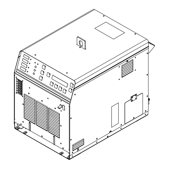
SECTION 12 − PARTS LIST Hardware is common and not available unless listed. See Figure 12-3 See Figure 12-2 Ref. 804218-E Figure 12-1. Wrappers Item Dia. Part Mkgs. Description Quantity Figure 12-1. Wrappers ... . . +217470 Panel, Side RH . - Page 71 Hardware is common and not available unless listed. Ref. 804219-D Figure 12-2. Front Panel Item Dia. Part Mkgs. Description Quantity Figure 12-2. Front Panel ....217323 ..Panel, Front .
- Page 72 Hardware is common and not available unless listed. 804220-B Figure 12-3. Rear Panel Item Dia. Part Mkgs. Description Quantity Figure 12-3. Rear Panel ....217324 Panel, Rear .
- Page 73 Hardware is common and not available unless listed. 272741-A Figure 12-4. Base w/Components Item Dia. Part Mkgs. Description Quantity Figure 12-4. Base w/Components ....217328 Frame, Lifting .
- Page 74 Hardware is common and not available unless listed. 272733-B Figure 12-5. Top Windtunnel Item Dia. Part Mkgs. Description Quantity Figure 12-5. Top Windtunnel ....218424 Windtunnel, Top .
- Page 75 Item Dia. Part Mkgs. Description Quantity Figure 12-5. Top Windtunnel (continued) ... . 220822 Xfmr, Current Bridge ..........
- Page 76 Hardware is common and not available unless listed. 272717-A Figure 12-6. Right Windtunnel Item Dia. Part Mkgs. Description Quantity Figure 12-6. Right Windtunnel ....216230 Windtunnel, RH .
- Page 77 Item Dia. Part Mkgs. Description Quantity Figure 12-6. Right Windtunnel (Continued) ....245842 Assy, Resistor ...........
- Page 78 Hardware is common and not available unless listed. 272731-A Figure 12-7. Right Windtunnel (400 V Model Only) Item Dia. Part Mkgs. Description Quantity Figure 12-7. Right Windtunnel (400 V Model Only) ....253366 Windtunnel, RH .
- Page 79 Item Dia. Part Mkgs. Description Quantity Figure 12-7. Right Windtunnel (400 V Model Only) (Continued) ....605339 Washer, Tooth .377 Id x 0.507 Od x .022t Stl Pld .
- Page 80 Hardware is common and not available unless listed. Figure 12-8. Left Windtunnel 272732-A Item Dia. Part Mkgs. Description Quantity Figure 12-8. Left Windtunnel ....216631 Windtunnel, Lh .
- Page 81 Item Dia. Part Mkgs. Description Quantity Figure 12-8. Left Windtunnel (Continued) ..PLG16, 121,122 ..131054 Housing Rcpt+Skts, (Service Kit) ........
- Page 82 Hardware is common and not available unless listed. 804300-A Figure 12-9. Hermaphroditic Blank Plug Assy Item Dia. Part Mkgs. Description Quantity Figure 12-9. Hermaphroditic Blank Plug Assy 224260 ....221440 O-Ring, .737 Id x .103 Cs .
- Page 83 804324-A Figure 12-10. Air−Cooled Output Extension Cables Item Dia. Part Mkgs. Description Quantity Figure 12-10. Air−Cooled Output Extension Cables 195404, 195405, And 300362 ....253841 Shell Assy, Connector −...
- Page 84 804411-A Figure 12-11. Liquid−Cooled Output Extension Cables Item Dia. Part Mkgs. Description Quantity Figure 12-11. Liquid−Cooled Output Extension Cables (195402, 195403, 300180, And 300598) ....253840 Connector Shell .
- Page 85 804404-A Figure 12-12. Heating Cables Item Dia. Part Mkgs. Description Quantity Figure 12-12. Heating Cables (300045, 300046, 300047, And 300049) ....254887 Connector Shell ..........
- Page 86 201432-G Figure 12-13. Quick Connect To Quick Connect Hose Item Dia. Part Mkgs. Description Quantity Figure 12-13. Quick Connect To Quick Connect Hose (204877) ....204955 Ftg, Plstc Coupler Qdisc x 1/4 Npt Female .
- Page 87 Hardware is common and not available unless listed. Replaceable Strap Strap Buckle Ref. 805176-C / Ref. 805174-C Figure 12-14. Induction Blanket And Sleeve Item Part Quantity Description Figure 12-14. Induction Blanket And Sleeve ..196666 Screw, 008−32 x 1.50 Rnd Hd−Slt Brs .
- Page 88 Item Part Description Quantity Figure 12-14. Induction Blanket And Sleeve (continued) ..195337 Induction Blanket Sleeve, 13-7/64 In. (229 mm) Wide, 41 In. (1041 mm) Long [8-5/8 In..... (219 mm) Dia Pipe] .
- Page 89 Hardware is common and not available unless listed. 24 22 Ref. 263983-C Figure 12-15. Rolling Inductor Complete Assembly Item Dia. Part Mkgs. Description Quantity Figure 12-15. Rolling Inductor Complete Assembly ... . . 262163 Plate, Side w/Pems Rolling Inductor .
- Page 90 Item Dia. Part Mkgs. Description Quantity Figure 12-15. Rolling Inductor Complete Assembly (Continued) ... . . 221099 ..Clamp, Strain Relief ..........
- Page 91 Item Dia. Part Mkgs. Description Quantity Figure 12-16. Rolling Inductor Mounting Arm Assembly ....263529 Plate, Swivel Induction Arm ........
- Page 92 Item Dia. Part Mkgs. Description Quantity Figure 12-17. Rolling Inductor Stand (Continued) ....269169 Plate, Locking Rolling Inductor Stand .......
- Page 93 Hardware is common and not available unless listed. 266226-B Figure 12-18. Travel Sensor Assembly w/Mounting Bracket Item Dia. Part Mkgs. Description Quantity Figure 12-18. Travel Sensor Assembly w/Mounting Bracket ....266229 O-Ring, 3.350 Id x 3.770 Od Silicone .
- Page 94 Hardware is common and not available unless listed. 265181-D Figure 12-19. IR Assembly w/Mounting Bracket Item Dia. Part Mkgs. Description Quantity Figure 12-19. IR Assembly w/Mounting Bracket ....265076 Sensor, Temperature IR Assembly .
- Page 95 Hardware is common and not available unless listed. 265916-F Figure 12-20. IR TC Control Box Item Dia. Part Mkgs. Description Quantity Figure 12-20. IR TC Control Box ....268033 Label, IR Connection Box .
- Page 96 Hardware is common and not available unless listed. 265149-C Figure 12-21. Regulator−Filter Air/Oil Separator Assembly Item Dia. Part Mkgs. Description Quantity Figure 12-21. Regulator−Filter Air/Oil Separator Assembly ....265146 Filter−Reg, 1/4 Npt 5 Micron 0−30psi Auto Drain w/N .
- Page 97 Effective January 1, 2018 (Equipment with a serial number preface of MJ or newer) This limited warranty supersedes all previous Miller warranties and is exclusive with no other guarantees or warranties expressed or implied. Warranty Questions? LIMITED WARRANTY − Subject to the terms and conditions below, 6 Months —...
- Page 98 Contact the Delivering Carrier to: File a claim for loss or damage during shipment. For assistance in filing or settling claims, contact your distributor and/or equipment manufacturer’s Transportation Department. © ORIGINAL INSTRUCTIONS − PRINTED IN USA 2018 Miller Electric Mfg. LLC 2018−01...
Need help?
Do you have a question about the 907689 and is the answer not in the manual?
Questions and answers