Sign In
Upload
Manuals
Brands
Miller Manuals
Heating System
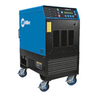
ProHeat 35 CE
Miller ProHeat 35 CE Manuals
Manuals and User Guides for Miller ProHeat 35 CE. We have
2
Miller ProHeat 35 CE manuals available for free PDF download: Owner's Manual
Miller ProHeat 35 CE Owner's Manual (98 pages)
Brand:
Miller
| Category:
Heating System
| Size: 2 MB
Table of Contents
Table of Contents
3
Declaration of Conformity
5
Section 1 − Safety Precautions − Read before Using
7
Symbol Usage
7
Induction Heating Hazards
7
Additional Symbols for Installation, Operation, and Maintenance
8
California Proposition 65 Warnings
9
Principal Safety Standards
9
EMF Information
9
Section 2 − Consignes de Sécurité − Lire Avant Utilisation
10
Signification des Symboles
10
Dangers Relatifs Au Soudage À L'arc
10
Dangers Supplémentaires en Relation Avec L'installation, Le Fonctionnement Et la Maintenance
11
Proposition Californienne 65 Avertissements
12
Principales Normes de Sécurité
12
Informations Relatives Aux CEM
12
Section 3 − Definitions
13
Additional Safety Symbols and Definitions
13
Miscellaneous Symbols and Definitions
15
Section 4 − Specifications
16
Serial Number and Rating Label Location
16
Specifications
16
Environmental Specifications
16
Section 5 − Installation
18
Selecting a Location
18
Dimensions and Weights
18
Electrical Service Guide
19
Connecting 3-Phase Input Power for 460/575 Volt Models
20
Connecting 3-Phase Input Power for 400/460 Volt IEC and CE Models
22
Coolant Jumper Connections
23
Power Source Output Connections
24
Remote 14 Receptacle RC14 Information and Connections
25
Remote 14 Socket Information
25
Temperature Recorder Receptacle RC9 Information and Connections
26
Temperature Recorder Socket Information
26
Secondary Insulation Protection
27
115 Volt AC Duplex Receptacle and Supplementary Protector
28
Locating Thermocouples
28
Attaching Welded Thermocouples
30
Using Contact Thermocouple Sensors
31
Using Non−Contact Temperature Sensors
31
Section 6 − Components and Controls
32
Controls
32
Section 7 − Setup and Operation
33
Safety Equipment
33
System Description
33
Important System Guidelines
33
Power Source/System Setup
33
Factory Defaults
35
Programming
35
Temperature-Based Control
35
Preheat
35
Bake-Out
36
PWHT (Post-Weld Heat Treat)
37
PWHT Operation
38
Custom Program
38
Remote Control
42
Power Vs Time Control
42
Manual Control
42
Rolling Inductor-Manual or Temperature Control Mode
43
Run Status
45
Temperature Based Control
45
Preheat, Bake-Out and PWHT Run Status Screen
45
Custom Program (Not Applicable with Rolling Inductor)
45
Manual Control
46
Remote Control
46
Power Vs Time Control
46
Parameters
46
Cooler
47
Real-Time Operation
47
System Operating Characteristics
50
Section 8 − Maintenance
52
Routine Maintenance
52
Calibration Verification Equipment
53
Calibration Verification Procedure
53
Initial Set up
53
TC Input/Output Check
53
Finishing Procedure
54
Section 9 − Safety Precautions for Servicing
57
Symbol Usage
57
Servicing Hazards
57
California Proposition 65 Warnings
58
Section 10 − Diagnostics & Troubleshooting
59
Operator Interface Indicators
59
Limit Conditions
60
Limit Condition Codes
60
Fault Conditions
61
Fault Condition Codes
61
Infrared Sensor Troubleshooting Guide
63
System Diagnostic Screens
63
Proheat 35 Firmware Versions and Compatibility
65
Removing Wrapper and Measuring Input Capacitor Voltage
66
Blowing out Inside of Unit
67
Section 11 − Electrical Diagram
68
Section 12 − Parts List
70
Advertisement
Miller ProHeat 35 CE Owner's Manual (76 pages)
Brand:
Miller
| Category:
Heating System
| Size: 1 MB
Table of Contents
Table of Contents
3
Section 1 − Safety Precautions − Read before Using
9
Symbol Usage
9
Induction Heating Hazards
9
Additional Hazards for Installation, Operation, and Maintenance
10
California Proposition 65 Warnings
11
Principal Safety Standards
11
EMF Information
11
Section 2 − Consignes de Sécurité − Lire Avant Utilisation
12
Signification des Symboles
12
Dangers Relatifs au Chauffage Par Induction
12
Symboles de Dangers Supplémentaires en Relation Avec L'installation
13
Le Fonctionnement et la Maintenance
13
Proposition Californienne 65 Avertissements
14
Principales Normes de Sécurité
14
Informations Relatives aux CEM
14
Section 3 − Definitions
15
Additional Safety Symbols and Definitions
15
Miscellaneous Symbols and Definitions
17
Section 4 − Specifications
18
Serial Number and Rating Label Location
18
Software Licensing Agreement
18
Information about Default Weld Parameters and Settings
18
Specifications
18
Environmental Specifications
18
Section 5 − Installation
21
Selecting a Location
21
Dimensions and Weights
21
Electrical Service Guide
22
Connecting 3-Phase Input Power for 460/575 Volt Models
23
Connecting 3-Phase Input Power for 400/460 Volt IEC and CE Models
25
Coolant Jumper Connections
26
Power Source Output Connections
27
Remote 14 Receptacle RC14 Information and Connections
28
Remote 14 Socket Information
28
Temperature Recorder Receptacle RC9 Information and Connections
29
Temperature Recorder Socket Information
29
Secondary Insulation Protection
30
115 Volt AC Duplex Receptacle and Supplementary Protector
31
Locating Thermocouples
31
Attaching Welded Thermocouples
33
Using Contact Thermocouple Sensors
34
Using Non−Contact Temperature Sensors
34
Section 6 − Components and Controls
35
Controls
35
Section 7 − Setup and Operation
36
Safety Equipment
36
System Description
36
Important System Guidelines
36
Power Source/System Setup
36
Factory Defaults
39
Programming
39
Temperature-Based Control
39
Remote Control
46
Power Vs Time Control
46
Manual Control
47
Rolling Inductor-Manual or Temperature Control Mode
47
Run Status
49
Temperature Based Control
49
Manual Control
50
Remote Control
50
Power Vs Time Control
50
Parameters
50
Cooler
51
Real-Time Operation
51
System Operating Characteristics
54
Section 8 − Maintenance
56
Routine Maintenance
56
Calibration Verification Equipment
57
Calibration Verification Procedure
57
Initial Set up
57
TC Input/Output Check
57
Finishing Procedure
58
Section 9 − Safety Precautions for Servicing
61
Symbol Usage
61
Servicing Hazards
61
California Proposition 65 Warnings
62
EMF Information
62
Section 10 − Diagnostics & Troubleshooting
63
Operator Interface Indicators
63
Limit Conditions
64
Limit Condition Codes
64
Fault Conditions
65
Fault Condition Codes
65
Infrared Sensor Troubleshooting Guide
67
System Diagnostic Screens
67
Proheat 35 Firmware Versions and Compatibility
69
Measuring/Discharging Input Capacitor Voltage before Working on Unit
70
Blowing out Inside of Unit
71
Section 11 − Electrical Diagram
72
Advertisement
Related Products
Miller ProHeat 35 Non CE
Miller ProHeat 35
Miller ProHeat Rolling Inductor
Miller Syncrowave 350 LX
Miller Millermatic 350P
Miller Invision 354MP
Miller INFINITY 35
Miller Invision 352 MPa Auto-Line CE
Miller Millermatic 350
Miller Continuum 350 and
Miller Categories
Welding System
Welding Accessories
Camera Accessories
Portable Generator
Motorcycle Accessories
More Miller Manuals
Login
Sign In
OR
Sign in with Facebook
Sign in with Google
Upload manual
Upload from disk
Upload from URL