Table of Contents
Advertisement
Quick Links
Card Reader
Quick Start Guide
UD30374B-A
Scan the QR code to get the user manual for detailed
information.
1 Installation
Installation Environment:
Indoor and outdoor installation are supported. If
installing the device indoors, the device should be at
least 2 meters away from the light, and at least 3
meters away from the window or the door. If installing
the device outdoors, you should apply Silicone sealant
among the cable wiring area to keep the raindrop
from entering.
The additional force shall be equal to three times the
weight of the equipment. The equipment and its
associated mounting means shall remain secure
during the installation. After the installation, the
equipment, including any associated mounting plate,
shall not be damaged.
Wall Mounting with Gang Box
1
Make sure the gang box is installed on the wall.
2
Secure the mounting plate on the gang box with the two supplied
screws (SC-KA4X25). Remove the back cover and route the cable
through the cable hole, wire the cables and insert the cables in the
gang box.
3
Align the device with the mounting plate, and secure the device on the
mounting plate with 2 supplied screw (SC-KM3X8T10-SUS-NL).
Wall Mounting without Gang Box
1
Drill holes on the wall or other surface according to the instructions on the
mounting template.
2
Secure the mounting plate on the wall with two supplied screws (SC-KA4X25).
Remove the back cover and route the cable through the cable hole, wire the cables
and recover the back cover.
3
Align the device with the mounting plate, and secure the device on the
mounting plate with 1 supplied screw (SC-CM4X14_5T10-SUSS).
Backlight
Direct
Direct Sunlight
Indirect Sunlight
Close to Light
Sunlight
through Window
through Window
Gang box is not supplied.
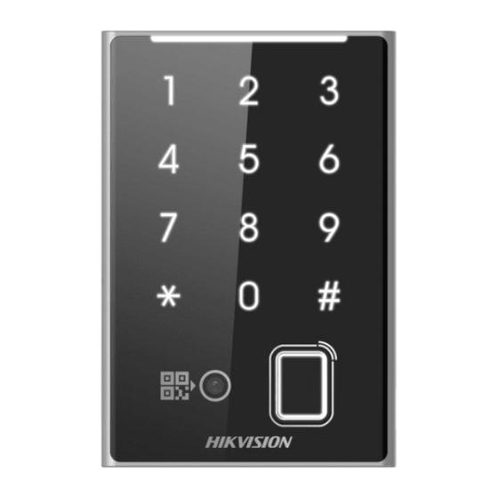
2 Appearance
LED
Indicator
Touch Key
Card/
Fingerprint
Presenting
Area
QR Code
Presenting Area
3 DIP Switch Description
DIP Switch Description
The DIP switch module is shown as left. The No. of DIP switch
from left to right is 1 to 8.
Represent 1 (ON) in binary mode
Represent 0 (OFF) in binary mode
DIP switch 1~4 refers to RS-485
address. When the switch towards 1, it
refers to 1. When the switch is towards
0, it refers to 0.
DIP switch 5 refers to card security. When the switch is towards 1, it will enable
M1 card encryption function and disable door open via NFC card. When the
switch towards 0, it will disable M1 card encryption function, enable door open
via NFC card, and read card No.
DIP switch 6 refers to Wiegand protocol or RS-485 protocol. When the switch is
towards 1, it refers to Wiegand protocol. When the switch towards 0, it refers to
RS-485 protocol.
DIP switch 7 refers to Wiegand Protocol (available when No. 6 is 1). When the
switch towards 1, it refers to Wiegand protocol of 26-bit. When the switch is
towards 0, it refers to Wiegand protocol of 34-bit.
DIP switch 8 refers to Matched Resistance (available for RS-485 protocol). When
the switch towards 1, it refers to Enable. When the switch is towards 0, it refers to
Disable.
Figures are for reference only.
The device which supports card, touch key, QR code and
fingerprint is taken as an example for the figure of appearance.
The function of touch key/QR code or fingerprint can only be
supported by some types of devices. For figures of appearance
or more information of other types of devices, please refer to
the user manual.
Power/RS-485/
Tamper
Wiegand Interface
Debugging Port (For
debugging only)
DIP Switch
RS-485
DIP Switch
DIP Switch
DIP Switch
DIP Switch
Address
1
2
3
4
Address 1
ON
OFF
OFF
OFF
Address 2
OFF
ON
OFF
OFF
Address 3
ON
ON
OFF
OFF
Address 4
OFF
OFF
ON
OFF
Advertisement
Table of Contents

Related Manuals for HIKVISION UD30374B-A


Summary of Contents for HIKVISION UD30374B-A
- Page 1 Secure the mounting plate on the gang box with the two supplied QR Code DIP Switch UD30374B-A Presenting Area screws (SC-KA4X25). Remove the back cover and route the cable through the cable hole, wire the cables and insert the cables in the gang box.
- Page 2 Do not aim the device at the sun or extra bright places. A PRODUCT DESCRIBED, WITH ITS HARDWARE, SOFTWARE AND FIRMWARE, ARE PROVIDED “AS IS” AND “WITH ALL FAULTS AND ERRORS”. HIKVISION MAKES NO blooming or smear may occur otherwise (which is not a...
Need help?
Do you have a question about the UD30374B-A and is the answer not in the manual?
Questions and answers