GE Multilin F650 Instruction Manual
Digital bay controller
Hide thumbs
Also See for Multilin F650:
- Instruction manual (801 pages) ,
- User manual (323 pages) ,
- User manual (259 pages)
Advertisement
Quick Links
g
GE Multilin
215 Anderson Avenue
L6E 1B3 Markham, ON -CANADA
T (905) 294 6222 F (905) 294 8512
E gemultilin@ge.com
Internet: www.GEMultilin.com
GE Consumer & Industrial
Multilin
F650
Digital Bay Controller
Instruction manual
GEK-106310Q
Firmware version: 3.40
EnerVista F650 Setup version: 3.40
Copyright © 2006 GE Multilin
GE Multilin
Avda. Pinoa, 10
48170 Zamudio SPAIN
T +34 94 485 88 00 F +34 94 485 88 45
E gemultilin.euro@ge.com
Advertisement

Related Manuals for GE Multilin F650


Summary of Contents for GE Multilin F650
- Page 1 Multilin F650 Digital Bay Controller Instruction manual GEK-106310Q Firmware version: 3.40 EnerVista F650 Setup version: 3.40 Copyright © 2006 GE Multilin GE Multilin GE Multilin Avda. Pinoa, 10 215 Anderson Avenue 48170 Zamudio SPAIN L6E 1B3 Markham, ON -CANADA T +34 94 485 88 00 F +34 94 485 88 45 T (905) 294 6222 F (905) 294 8512 E gemultilin.euro@ge.com...
- Page 2 TABLE OF CONTENTS 1. GETTING STARTED 1.1 IMPORTANT PROCEDURES 1.1.1 CAUTIONS AND WARNINGS ................1-1 1.1.2 INSPECTION CHECKLIST ................1-4 1.1.3 SAFETY INSTRUCTIONS ................. 1-6 1.2 OVERVIEW 1.2.1 INTRODUCTION TO 650 FAMILY OF RELAYS ..........1-7 1.2.2 HARDWARE ARCHITECTURE ................. 1-7 1.2.3 SOFTWARE ARCHITECTURE................
- Page 3 TABLE OF CONTENTS 3.5 TRANSCIEVER OPTICAL POWER BUDGET VERSUS LINK LENGTH 4. HUMAN INTERFACES. 4.1 ENERVISTA 650 SETUP SOFTWARE INTERFACE SETTINGS & ACTUAL 4.1.1 INTRODUCTION ....................4-1 4.1.2 ENERVISTA 650 SETUP SOFTWARE OVERVIEW..........4-1 VALUES 4.1.3 MAIN SCREEN ....................4-3 4.1.4 COMMUNICATION MENU .................4-4 4.1.5 FILE MANAGEMENT ..................4-6 4.1.6...
- Page 4 TABLE OF CONTENTS 5.5 CONTROL ELEMENTS 5.5.1 SETTING GROUP ................... 5-83 5.5.2 UNDERFREQUENCY ELEMENT (81U)............5-84 5.5.3 OVERFREQUENCY ELEMENT (81O) ............5-84 5.5.4 SYNCHRONISM CHECK ELEMENT - SYNCHROCHECK (25) ..... 5-85 5.5.5 AUTORECLOSE (79)..................5-94 5.5.6 BREAKER FAILURE ELEMENT (50BF)............5-101 5.5.7 VT FUSE FAILURE ELEMENT (VTFF) ............
- Page 5 TABLE OF CONTENTS 6.2.12 RECORD STATUS ...................6-25 6.3 METERING 6.3.1 PRIMARY VALUES ..................6-29 6.3.2 SECONDARY VALUES ..................6-33 6.3.3 PHASOR DIAGRAM ..................6-35 6.3.4 FREQUENCY ....................6-35 6.4 INPUTS / OUTPUTS 6.4.1 CONTACT INPUTS ..................6-36 6.4.2 CONTACT OUTPUT STATUS................6-37 6.4.3 CONTACT OUTPUT OPERATES ..............6-37 6.4.4 CONTACT OUTPUT RESETS .................6-38 6.4.5...
- Page 6 TABLE OF CONTENTS 10. COMMISSIONING 10.1 VISUAL INSPECTION 10.2 GENERAL CONSIDERATIONS ON THE POWER SUPPLY NETWORK 10.3 ISOLATION TESTS 10.4 INDICATORS 10.5 POWER SUPPLY TESTING 10.6 COMMUNICATIONS 10.7 VERIFICATION OF MEASUREMENT 10.7.1 VOLTAGES...................... 10-7 10.7.2 PHASE CURRENTS ..................10-7 10.7.3 ACTIVE, REACTIVE POWER, AND COSJ METERING .........
- Page 7 TABLE OF CONTENTS 11.3 EXAMPLE 3: PROCEDURE TO SET AN OPERATION 11.3.1 DESCRIPTION OF THE EXERCISE ..............11-8 11.3.2 PROCEDURE ....................11-8 11.3.3 TEST.......................11-10 12. FREQUENTLY ASKED 12.1 COMMUNICATIONS QUESTIONS 12.2 PROTECTION 12.3 CONTROL AND HMI 12.4 RELAY CONFIGURATION 13. TROUBLESHOOTING 13.1 SYMPTOMS AND RECOMMENDED ACTIONS GUIDE A.
- Page 8 D.5 IEC 60870-5-104 POINT LIST E. PROCOME PROTOCOL E.1 PROCOME PROTOCOL F. FACTORY DEFAULT LOGIC F.1 FACTORY DEFAULT LOGIC G. FACTORY DEFAULT G.1 FACTORY DEFAULT SETTINGS CONFIGURATION G.2 FACTORY DEFAULT CONFIGURATION H. MISCELLANEOUS H.1 GE MULTILIN WARRANTY GEK-106310Q F650 Digital Bay Controller...
- Page 9 TABLE OF CONTENTS VIII F650 Digital Bay Controller GEK-106310Q...
- Page 10 1 GETTING STARTED 1.1 IMPORTANT PROCEDURES 1 GETTING STARTED 1.1IMPORTANT PROCEDURES 1.1.1 CAUTIONS AND WARNINGS To help ensure years of trouble free operation, please read through the following chapter for information to help guide you through the initial installation procedures of your new relay. BEFORE ATTEMPTING TO INSTALL OR USE THE RELAY, IT IS IMPERATIVE THAT ALL WARNINGS AND CAUTIONS IN THIS MANUAL ARE REVIEWED TO HELP PREVENT PERSONAL INJURY, EQUIPMENT DAMAGE, AND/OR DOWNTIME.
- Page 11 Check that the relay is fully operative. Figure 1–2: MODULE WITHDRAWAL/INSERTION GE Multilin will not be responsible for any damage of the relay, connected equipment or personnel whenever these safety rules are not followed.
- Page 12 It is very important, for safety reasons not to change or switch the terminals for CTs and VTs. AC Input Terminals Figure 1–3: REAR VIEW OF F650 UNIT will not be responsible for any damage of the relay, connected equipment or personnel GE Multilin whenever these safety rules are not followed. GEK-106310Q F650 Digital Bay Controller...
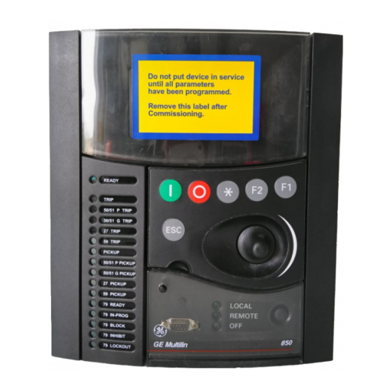
- Page 13 1.1 IMPORTANT PROCEDURES 1 GETTING STARTED 1.1.2 INSPECTION CHECKLIST Unwrap the relay and inspect the relay for physical damage. Verify that the model on the label on the side of the relay matches the model ordered. Figure 1–4: IDENTIFICATION LABEL (A4455P6) Please ensure that you received the following items with your relay: •...
- Page 14 1 GETTING STARTED 1.1 IMPORTANT PROCEDURES For product information, instruction manual updates, and the latest software updates, please visit the GE Multilin Home Page www.geindustrial.com/multilin. Note: If there is any physical damage detected on the relay, or any of the contents listed are missing, please...
- Page 15 GE Multilin will not be responsible for any damage to the relay or connected equipment whenever this elemental safety rule is not followed.
- Page 16 1 GETTING STARTED 1.2 OVERVIEW 1.2OVERVIEW 1.2.1 INTRODUCTION TO 650 FAMILY OF RELAYS Historically, substation protection, control and metering functions were performed with electromechanical equipment. This first generation of equipment was gradually replaced by analog electronic equipment (called static devices), most of which emulated the single-function approach of their electromechanical precursors.
- Page 17 1.2 OVERVIEW 1 GETTING STARTED Figure 1–6: 650 CONCEPT BLOCK DIAGRAM Contact Inputs/Outputs are signals associated to the physical input/output contacts in the relay CT and VT inputs are signals coming from the inputs of current and voltage transformers, used for monitoring the power system signals.
- Page 18 1 GETTING STARTED 1.2 OVERVIEW 1.2.3 SOFTWARE ARCHITECTURE The firmware (software embedded in the relay) has been designed using object oriented programming techniques (OOP). These techniques are based on the use of objects and classes, and provide the software architecture with the same characteristics as the hardware architecture, i.e., modularity, scalability and flexibility.
- Page 19 1.2 OVERVIEW 1 GETTING STARTED Figure 1–7: COMMUNICATIONS ARCHITECTURE (B6816F1) 1-10 F650 Digital Bay Controller GEK-106310Q...
- Page 20 1.3.2 INSTALLATION After ensuring the minimum requirements for using EnerVista 650 Setup are met (see previous section), use the following procedure to install the EnerVista 650 Setup from the GE EnerVista CD. Insert the GE EnerVista CD into your CD-ROM drive.
Need help?
Do you have a question about the Multilin F650 and is the answer not in the manual?
Questions and answers