Table of Contents
Advertisement
Advertisement
Table of Contents

Related Manuals for Phoenix Contact UM EN FL WLAN 5100


Summary of Contents for Phoenix Contact UM EN FL WLAN 5100
-
Page 1: User Manual
UM EN FL WLAN 5100 User manual UM EN FL WLAN 5100... - Page 2 User manual UM EN FL WLAN 5100 2013-06-05 Designation: UM EN FL WLAN 5100 Revision: Order No.: — This user manual is valid for: Designation Revision Order No. FL WLAN 5100 2700718 FL WLAN 5101 2701093 PHOENIX CONTACT 7191_en_04...
- Page 3 How to contact us Internet Up-to-date information on Phoenix Contact products and our Terms and Conditions can be found on the Internet at: www.phoenixcontact.com Make sure you always use the latest documentation. ...
- Page 4 The receipt of technical documentation (in particular user documentation) does not consti- tute any further duty on the part of Phoenix Contact to furnish information on modifications to products and/or technical documentation. You are responsible to verify the suitability and intended use of the products in your specific application, in particular with regard to observ- ing the applicable standards and regulations.
-
Page 5: Table Of Contents
3.6.4 Via BootP/TFTP ................... 44 Operating modes of the device................45 3.7.1 Operating mode: access point ............. 45 3.7.2 Operating mode: client ................. 46 3.7.3 Operating mode: repeater ..............49 3.7.4 Operating mode: machine admin ............52 7179_en_04 PHOENIX CONTACT... - Page 6 Menu/functions ........................69 Parameter list for the configuration ..............70 Diagnostics ..........................83 WLAN signal strength diagnostics on the client........... 83 Diagnostics of WLAN channel assignment on the access point ......85 Technical data .........................87 Ordering data ...................... 89 PHOENIX CONTACT 7179_en_04...
- Page 7 WLAN 5100 – next generation industrial WLAN Industrial WLAN network solutions from Phoenix Contact open up new possibilities for creating production and logistics processes more efficiently, reliably, and simply. The fields of application are: • Reliable, safe and fast communication with mobile or moving automation and production systems.
-
Page 8: Technical Description
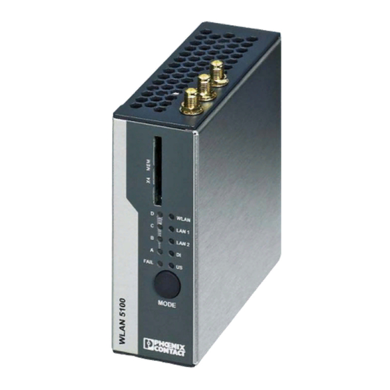
Connections: COMBICON for supply voltage (10 ... 36 V DC), 2 x RJ45 ports for LAN – Configuration via WBM, SNMP, and CLI via SSH/Telnet – Security functions: 802.11i: WPA2, WPA-PSK, TKIP, AES Connections for three antennas (MiMo technology/connection method: – RSMA/not supplied as standard) Figure 1-1 FL WLAN AP 5100 PHOENIX CONTACT 7191_en_03... -
Page 9: Fl Wlan 510X Country Registrations
This equipment generates, uses and can radiate radio frequency energy and, if not installed and used in accordance with the instructions, may cause harmful interference to radio communications. 7191_en_03 PHOENIX CONTACT... - Page 10 This device complies with Industry Canada license-exempt RSS standard(s). Operation this subject to the following two conditions: (1) this device may not cause interference, and (2) this device must accept any interference, including interference that may cause undesired operation of the device. PHOENIX CONTACT 7191_en_03...
- Page 11 Under such configuration, the IC RSS-102 radiation exposure limits set forth for a population/uncontrolled environment can be satisfied. Any changes or modifications not expressly approved by the manufacturer could void the users authority to operate this equipment. 7191_en_03 PHOENIX CONTACT...
-
Page 12: Firmware
FL WLAN 510x Firmware Table 1-1 Firmware version Functionality FW 1.60 The “machine admin mode” (second SSID) and DHCP server func- tions are available as of this FW version. PHOENIX CONTACT 7191_en_03... -
Page 13: Mounting
COMBICON connections for supply voltage and one digital input or output (X3) Two RJ45 Ethernet connections with 100 Mbps (X1, X2) Mode button for setting various pre-configured states Status and diagnostic LEDs Slot for optional SD memory card (X4) RSMA antenna connections (female) (X5, X6, X7) 7191_en_03 PHOENIX CONTACT... -
Page 14: Electrical Connection
DIN rail mounting Use the DIN rail guide to position the module onto the upper edge of the DIN rail, and snap the module into place by pushing it downward. Figure 2-3 Snapping the module onto the DIN rail PHOENIX CONTACT 7191_en_03... - Page 15 Insert a suitable tool (e.g., flat-bladed screwdriver) into the latch and pull the latch downward (B1). Figure 2-4 Removing the module from the DIN rail 2.1.2.3 Housing dimensions WLAN LAN 1 LAN 2 FAIL MODE Figure 2-5 Housing dimensions with protruding parts in mm 7191_en_03 PHOENIX CONTACT...
- Page 16 Use the two screws provided to secure the device to the base plate. The two 4.5 mm bore holes can be used for mounting. 2.1.2.5 Dimensions of the mounting kit and drill hole template Figure 2-7 Dimensions of the mounting kit and drill hole template in mm PHOENIX CONTACT 7191_en_03...
- Page 17 2.1.2.6 Mounting in the IP65 housing Phoenix Contact offers an IP65 housing (FL RUGGED BOX OMNI-1) specifically for use in conjunction with the FL WLAN 510x. Three omnidirectional antennas (dual band, 2.4 GHz, and 5 GHz) are supplied as standard with the housing. They are screwed directly onto the housing.
- Page 18 200 mm to 500 mm between the antennas are mechanically feasible, this may lead to further improvement. For the same reason, antennas should not be screwed directly onto the device. Figure 2-10 Do not screw several antennas onto the device. PHOENIX CONTACT 7191_en_03...
-
Page 19: Startup And Configuration
UV radiation. The same applies to the antenna which is connected to the cable and which functions as a cable termination. The antenna must meet the requirements of EN 60079-0 with regard to housing and electrostatic discharge. 7191_en_03 PHOENIX CONTACT... -
Page 20: Status And Diagnostic Indicators
Whether data transmission occurs depends on whether the passwords and certificates are valid. A WLAN connection can therefore exist even if data cannot be transmitted. If WLAN authentication fails, this is indicated in the log file. Half duplex data transmission: blue; if flashing, data transmission is active PHOENIX CONTACT 7191_en_03... -
Page 21: Meaning Of The Lan1/2 Indicators
Typical operating settings for the FL WLAN 510x can be set using the MODE button on the front of the device. The possible settings can be found in table “Operating modes” on page 22. A selection of the key settings is also available directly on the device. 7191_en_03 PHOENIX CONTACT... -
Page 22: General Sequence
An address is assigned only once in order to easily supply a single device with an IP address (e.g., a PC that is connected for configuration purposes). In this mode, the device can be accessed under IP 192.168.0.254. PHOENIX CONTACT 7191_en_03... -
Page 23: Changing The Firmware Image Using The Mode Button
Press and hold down the MODE button. • Switch on the power supply. • Release the MODE button within five seconds once the link quality LEDs (A+B+C+D) have started to flash yellow. The device now switches the firmware image and reboots. 7191_en_03 PHOENIX CONTACT... -
Page 24: Connection To A Pc
Press the MODE button briefly several times to select mode “BC” (LED). • Confirm the mode by pressing the MODE button longer (> 2 sec). • The temporary DHCP server automatically assigns an IP address to the configuration PC. The FL WLAN 510x receives the IP address 192.168.0.254. PHOENIX CONTACT 7191_en_03... -
Page 25: Assigning The Ip Address Via Bootp (With Ipassign)
“Quick setup/IP address assignment” web page. The program opens and the start screen of the addressing tool appears. The program is mostly in English for international purposes. However, the program buttons change according to the country-specific settings. 7191_en_03 PHOENIX CONTACT... - Page 26 The following information is displayed in the window which opens: – IP address of the PC – MAC address of the selected device – IP parameters of the selected device (IP address, subnet mask, and gateway address) – Any incorrect settings PHOENIX CONTACT 7191_en_03...
- Page 27 The window that opens informs you that IP address assignment has been successfully completed. It gives an overview of the IP parameters that have been transmitted to the device with the MAC address shown. To assign IP parameters for additional devices: • Click on “Back”. 7191_en_03 PHOENIX CONTACT...
-
Page 28: Using The Digital Input And Output
Trigger WLAN roaming Yes, via configuration Switch WLAN interface Yes, via configuration on/off Show status of WLAN Yes, via configuration interface Startup via the web interface WBM of the device is optimized for Internet Explorer 8.0 or later PHOENIX CONTACT 7191_en_03... -
Page 29: General Information In The Web Interface
An administrator is not logged in at present. The icon also acts as the login button. The active configuration differs from the saved configuration for the device. To save the active configuration, simply click on the icon. 7191_en_03 PHOENIX CONTACT... - Page 30 Table 3-6 Meaning of the buttons Icon Meaning This button deletes the entries made since the last saved entry This button applies the current settings, but does not save them This button applies and saves the current settings PHOENIX CONTACT 7191_en_03...
-
Page 31: Quick Setup
First, select the language for user management, the web page interface. The help text displayed when you move the mouse cursor over the (?) is shown in the selected language. IP address assignment Static: The static IP address, subnet mask, and gateway address can be set here. 7191_en_03 PHOENIX CONTACT... - Page 32 The settings primarily affect the device when it is used in the 5 GHz WLAN band. A wireless license is not necessarily available for each country that can be selected here. PHOENIX CONTACT 7191_en_03...
- Page 33 Startup and configuration Operating mode Under “Operating Mode”, you can define whether the device assumes the function of an access point or a client in the network. Figure 3-7 “Quick Setup” web page 7191_en_03 PHOENIX CONTACT...
-
Page 34: Operation As An Access Point
Frequency Selection, DFS). In doing so, the connection may be interrupted for at least one minute during a channel switchover. NOTE: This operating mode is prescribed by law within the EU for outdoor operation and must be used. PHOENIX CONTACT 7191_en_03... - Page 35 The change is only applied when you click on “Apply”. To permanently save the change beyond a device restart, click on “Apply&Save”. We strongly recommend that you change the administrator password the first time you use the device in order to avoid unauthorized access to the web interface. 7191_en_03 PHOENIX CONTACT...
-
Page 36: Operation As A Client
Other client modes are described in “Operating modes of the device” on page 45. Confirm your selection with “Apply” or “Apply&Save”. The WLAN wireless interface is activated automatically by clicking on “Apply” in the “Quick Setup” menu. It is deactivated by default. PHOENIX CONTACT 7191_en_03... - Page 37 Please note that any existing connections will be interrupted during scanning. All frequencies that can be used in the 2.4 GHz and 5 GHz band (see “Indoor” checkbox) are scanned for access points. 7191_en_03 PHOENIX CONTACT...
- Page 38 Other encryption options are available in the “WLAN” menu. We strongly recommend using secure encryption in order to protect your network against unauthorized access. In order to reach full data throughput under WLAN 802.11n, WPA2-PSK (AES) encryption must be used. PHOENIX CONTACT 7191_en_03...
- Page 39 The change is only applied when you click on “Apply”. To permanently save the change beyond a device restart, click on “Apply&Save”. We strongly recommend that you change the administrator password the first time you use the device in order to avoid unauthorized access to the web interface. 7191_en_03 PHOENIX CONTACT...
-
Page 40: Sd Card For Saving The Device Configuration
Only SD cards from Phoenix Contact can be used (see “Ordering data” on page 89). Do not delete the existing license key on SD cards from Phoenix Contact. -
Page 41: Inserting The Sd Card
SD card to the WLAN device. The “Perform action"” menu for this purpose is located under “System” in the web interface. The device can also be operated without an SD card. The configuration is also stored in the internal memory of the device. 7191_en_03 PHOENIX CONTACT... -
Page 42: Saving The Device Configuration
Folder for saving the configuration file on the SD card All configuration data is saved, with the exception of some parameters that should not be overwritten when the configuration data is later transferred to other devices via the SD card. PHOENIX CONTACT 7191_en_03... -
Page 43: Firmware Update
Now insert the SD card into the device. • Switch on the device with the card inserted. • LEDs A - D form a light sequence and indicate that the firmware is being downloaded. After rebooting, the new firmware version is available. 7191_en_03 PHOENIX CONTACT... -
Page 44: Via Bootp/Tftp
Switch off the device on which you wish to install the new firmware, e.g., by interrupting the power supply. • Switch on the device while holding down the MODE button. Do not release the button until the LEDs change from yellow to green. PHOENIX CONTACT 7191_en_03... -
Page 45: Operating Modes Of The Device
This can vary to a greater or lesser extent depending on how much data the application requests via the individual clients. If the application has time requirements, the number of clients must also be taken into consideration. For example, for 7191_en_03 PHOENIX CONTACT... -
Page 46: Operating Mode: Client
FTB: only between devices from the same manufacturer, all devices transmit transparently on Layer 2/3, Client the technical implementation depends on the manufacturer Ethernet Multiple devices, Layer 2 or Layer 3 Figure 3-14 Overview of the various client modes PHOENIX CONTACT 7191_en_03... - Page 47 WLAN. In Single Client Bridge (SCB) mode, the data is transmitted transparently on Layer 2. Only the device whose MAC address is entered for FL WLAN 510x can be accessed via WLAN. 7191_en_03 PHOENIX CONTACT...
- Page 48 An FTB connection between the FL WLAN 510x and the device (access point) of a third party manufacturer can only work if the latter uses the same, non-standardized implementation. This is possible, but rather unlikely. More detailed information regarding interoperability in FTB mode with other manufacturers cannot be provided. PHOENIX CONTACT 7191_en_03...
-
Page 49: Operating Mode: Repeater
In repeater mode, the data rate is at least halved as each data packet is received and sent. – The coverage area of a WLAN network is enlarged. – The configuration matches that of a client. – Only with PSK encryption. 7191_en_03 PHOENIX CONTACT... - Page 50 The WLAN repeater now scans for the corresponding SSID and establishes the connection. The “WLAN” LED lights up blue after successful connection establishment. The MAC address of the connected device and information regarding the connection quality are displayed in the “Interface Status (WLAN)” menu. PHOENIX CONTACT 7191_en_03...
- Page 51 SSID, one security mode, and one passkey. The same applies to the clients that are connected to the repeaters via WLAN. All devices use a single wireless channel. The use of WPS is not supported in repeater mode. 7191_en_03 PHOENIX CONTACT...
-
Page 52: Operating Mode: Machine Admin
SSID. This access is configured under “Machine admin configuration”. This menu item is shown in the menu on the left after selecting “Machine Admin” mode. Figure 3-6 “Machine Admin” mode can be selected on the “WLAN” page. PHOENIX CONTACT 7191_en_03... - Page 53 The IP addresses under “Grant access to IP” must be in the same address area as the WLAN 510x. See “Network configuration”. Figure 3-7 The required settings for maintenance access connection can be entered in the “Machine admin configuration” menu 7191_en_03 PHOENIX CONTACT...
-
Page 54: Profinet Assistance Mode
MODE button (mode 3). Figure 3-8 “PROFINET assistance mode” should be enabled in PROFINET applications The following settings are activated in “PROFINET assistance mode”: IP address assignment is via DCP PROFINET data is transmitted with top priority PHOENIX CONTACT 7191_en_03... - Page 55 When setting the PLC please observe that the PROFINET update time must also be adjusted according to the number of PROFINET devices. The more PROFINET devices used in the WLAN network, the higher the required PROFINET update time. 7191_en_03 PHOENIX CONTACT...
-
Page 56: Wi-Fi Protected Setup (Wps)
If the device is operating in PROFINET assistance mode, the PROFINET packets are classed as high priority based on their Ethertype value. Strict prioritization is used. “Non-PROFINET traffic” is now limited to a maximum data throughput of 10 Mbps. PHOENIX CONTACT 7191_en_03... -
Page 57: Cluster Management
The “Clustering” parameter must be activated (default) in the “Cluster Configuration” menu in order to apply the configuration. Clicking on “Manage Cluster Group” opens the “Cluster Group Configuration” pop-up window. 7191_en_03 PHOENIX CONTACT... - Page 58 The access points that will be added to the cluster are now selected in the last column, “Cluster Member” (see Figure 3-10 on page 59). Up to 20 access points can be grouped into a cluster. An Ethernet network can have several clusters. PHOENIX CONTACT 7191_en_03...
- Page 59 “Apply” to start creating and configuring the cluster. The configuration of the preset access point is transferred to all the other devices. The process can take a little time depending on the number of access points in the cluster. 7191_en_03 PHOENIX CONTACT...
- Page 60 Figure 3-11 Automatic configuration of the selected cluster A table containing all the access points belonging to the cluster then appears in the “Cluster Configuration” window. They can be identified by their IP address or MAC address. PHOENIX CONTACT 7191_en_03...
- Page 61 “Cluster Name” in the “Cluster Group Configuration” window. An inquiry scan is triggered by clicking on “Start”. The new device appears in the list and can be added to the cluster via the checkbox under “Cluster Member”. Save the configuration with “Apply&Save”. 7191_en_03 PHOENIX CONTACT...
-
Page 62: Identifying Cluster-Relevant Parameters In The Web Interface
WLAN SSID – Security settings (access control list, MAC address filter) – User names and passwords – QoS settings – WLAN settings The following information can also be viewed within a cluster: – Diagnostic information – Connected clients PHOENIX CONTACT 7191_en_03... -
Page 63: Properties Of Cluster Management
Various files can be transferred between the configuration PC and the device using HTTP(s) or TFTP: Table 3-1 File transfer File Upload Download Device documentation SNMP MIB files Security context CA root certificate Client certificates Event log files Firmware files Device configuration 7191_en_03 PHOENIX CONTACT... -
Page 64: Dhcp Server
The subnet mask is assigned by the DHCP server. Gateway Assignment of the gateway in format 0.0.0.0 Lease time Time interval in seconds during which the IP address is valid. PHOENIX CONTACT 7191_en_03... -
Page 65: Event Handling
Always Yes, configurable configurable Error LED ON/OFF Yes, Yes, configurable configurable Client connected/not Yes, Always Always connected configurable Roaming performed Yes, Always Yes, configurable configurable Client mode changed Yes, Always Yes, Yes, Yes, configurable configurable configurable configurable 7191_en_03 PHOENIX CONTACT... -
Page 66: Selecting Events In Web-Based Management
Various events can be selected on the “System Events” web page, the occurrence of which generates an external Syslog entry or sends an SNMP trap. In addition, the SNMP trap receivers are defined here. Figure 3-15 Possible system events that can be selected PHOENIX CONTACT 7191_en_03... - Page 67 Startup and configuration 7191_en_03 PHOENIX CONTACT...
- Page 68 FL WLAN 510x PHOENIX CONTACT 7191_en_03...
-
Page 69: Menu/Functions
All information regarding the diagnostics of wireless connections can be found in this area. Help On web pages, a (?) appears after each parameter. When you place the mouse pointer over it, information regarding the parameter is displayed in a flyout window. 7191_en_03 PHOENIX CONTACT... -
Page 70: Parameter List For The Configuration
A chronologically ordered table overview displays the event messages of the device. The complete log file can be downloaded via a link. Connected Devices Only in access point mode: the connected devices (client mode) and their parameters are displayed in table format. PHOENIX CONTACT 7191_en_03... - Page 71 It can be a maximum of 32 characters long. Letters, numbers, and the following characters are permitted: $@&/()=?[]{}+*-_<>. WLAN Band Selection of the frequency band. Other operating modes according to IEEE 802.11 are available in the “Advanced WLAN” menu. 7191_en_03 PHOENIX CONTACT...
- Page 72 The new password must be between 8 and 14 characters long. The new password is not activated until you log out and log back in again. Retype Password Retype the new password you wish to use. PHOENIX CONTACT 7191_en_03...
- Page 73 Assignment of the gateway in format 0.0.0.0 Lease time Time interval in seconds during which the IP address is valid. WLAN WLAN Configuration - Basic settings Activate WLAN interface The disabled WLAN interface prevents any communication at the wireless interface. 7191_en_03 PHOENIX CONTACT...
- Page 74 SSID in the beacons of the access point it may not be possible to find the correct access point. WLAN band Selection of the frequency band. Other operating modes according to IEEE 802.11 are available in the “Advanced WLAN” menu. PHOENIX CONTACT 7191_en_03...
- Page 75 802.11n, WPA2-PSK (AES) encryption must be used. Passkey Key during the initialization of WPA encryption. Note: for maximum security, a random alphanumeric string (up to 63 characters) should be used. Letters, numbers, and the following characters are permitted: $%@&/()=?[]{}+*-_<>. 7191_en_03 PHOENIX CONTACT...
- Page 76 Wireless connections over large distances (> 3000 m) 3000 m) require the timeout configuration to be modified. Change this parameter only if the distance is over 3000 m. The setting must be the same for the access point and the client. PHOENIX CONTACT 7191_en_03...
- Page 77 10 Mbps. Allow configuration via If activated, the device can be configured via its WLAN WLAN interface (must be deactivated for PROFIsafe applications). The configuration interfaces (WBM, SNMP, CLI via Telnet/SSH) are still available via Ethernet. 7191_en_03 PHOENIX CONTACT...
- Page 78 Upload: local PC (host) to WLAN device TFTP server IP address In the case of TFTP, the file name and path of the TFTP server must be specified here. Generate new Generate a new certificate. SSH hostkey Host key for the SSH session PHOENIX CONTACT 7191_en_03...
- Page 79 Advanced configuration (pop-up window) Upload certificate Upload certificate via HTTP: select a file by clicking on “Upload a file” or drag the file over this button. Alternatively, the certificate can be uploaded via a TFTP server. 7191_en_03 PHOENIX CONTACT...
- Page 80 For encryption of the “machine admin network”. Note: for maximum security, a random alphanumeric string (up to 63 characters) should be used. Letters, numbers, and the following characters are permitted: $%@&/()=?[]{}+*-_<>. The password must be at least eight characters long. PHOENIX CONTACT 7191_en_03...
- Page 81 Graphic In client mode, the “RSSI Graph” web page has a graphical RSSI logger which displays the time curve for the RSSI values on the client. The data displayed is cleared when the web page is exited. 7191_en_03 PHOENIX CONTACT...
- Page 82 FL WLAN 510x PHOENIX CONTACT 7191_en_03...
-
Page 83: Diagnostics
The MAC address of the connected access point and the current WLAN signal strength (RSSI) are displayed at the top of the window. Figure 5-1 Display of the current WLAN signal strength on the client 7191_en_03 PHOENIX CONTACT... - Page 84 Measurement is stopped when you exit the web page. Figure 5-2 Display of the current signal strength as a bar graph PHOENIX CONTACT 7191_en_03...
-
Page 85: Diagnostics Of Wlan Channel Assignment On The Access Point
In access point mode, the WLAN networks that are within range are displayed in the “Diagnostics” – “Channel Allocation” menu when you click on “Scan”. Figure 5-3 Display of WLAN channel assignment on the access point 7191_en_03 PHOENIX CONTACT... - Page 86 FL WLAN 510x PHOENIX CONTACT 7191_en_03...
-
Page 87: Technical Data
III, IEC 61140, EN 61140, VDE 0140-1 Interfaces RJ45 Ethernet interface Number Connection format RJ45 socket on the device Data transmission speed 10/100 Mbps Segment length 100 m IP address assignment BootP Wireless interface Antenna connection 3 x RSMA female 7191_en_03 PHOENIX CONTACT... - Page 88 Class B Radio interference field strengths according to EN 55022 Class a Electrostatic discharge (ESD) according to EN 61000-4-2 Contact discharge: ±6 kV Air discharge: ±8 kV Electromagnetic fields according to IEC 61000-4-3 10 V/m; Criterion A PHOENIX CONTACT 7191_en_03...
-
Page 89: Ordering Data
2.4 GHz h/v 360°/30°, 5 GHz h/v 260°/16° opening angle, N (male), IP68 Omnidirectional antenna with protection against vandalism, 2.4 GHz, RAD-ISM-2400-ANT-VAN- 2701358 3 dBi gain, IP55 protection, 1.5 m cable length, RSMA connection (male), 3-0-RSMA h/v 360°/85° opening angle 7191_en_03 PHOENIX CONTACT... - Page 90 Antenna cable, 10 m in length; N (male) -> N (male), attenuation approx. RAD-CAB-EF393- 10M 2867665 0.45 dB at 2.4 GHz; impedance 50 ohms Antenna cable, 15 m in length; N (male) -> N (male), attenuation approx. RAD-CAB-EF393- 15M 2867634 0.45 dB at 2.4 GHz; impedance 50 ohms PHOENIX CONTACT 7191_en_03...
- Page 91 FL CAT5 PATCH 7,5 2832616 Patch cable, CAT5, pre-assembled, 10.0 m long, 10 pieces FL CAT5 PATCH 10 2832629 PHOENIX CONTACT GmbH & Co. KG Flachsmarktstr. 8 32825 Blomberg Germany + 49 - (0) 52 35 - 3-00 + 49 - (0) 52 35 - 3-4 12 00 www.phoenixcontact.com...
- Page 92 FL WLAN 510x PHOENIX CONTACT 7191_en_03...
- Page 93 “expired”, but it cannot be reused with other parameters under any circumstances. Phoenix Contact provides notification of ASN1 SNMP objects by publishing their descriptions on the Internet. Reading SNMP objects is not password-protected. However, a password is required for read access in SNMP, but this is set to “public”, which is usual for network devices, and...
- Page 94 FL IL 24 BK-B FL IL 24 BK-B Ord.-No.: 2833000 Ord.-No.: 2833000 FAIL FAIL FL BLUETOOTH AP Bluetooth Access Point Ord No.: 27 37 999 LINK LINK 10/100 10/100 Bluetooth 687407022 Figure 6-1 Schematic view of SNMP PHOENIX CONTACT 7191_en_03...
- Page 95 Each client synchronizes its system time with that of an SNTP server – Time synchronization is carried out at fixed synchronization intervals – The local system time of the client is thus constantly corrected. – Synchronization is carried out in Universal Time Coordinated (UTC) format 7191_en_03 PHOENIX CONTACT...
- Page 96 Manual configuration: the module has a realtime clock with buffer battery. This means that the clock continues running even without an external power supply. Manual configuration is recommended for the certificate to be validated. Please note that it is not possible to automatically switch between daylight savings and standard time. PHOENIX CONTACT 7191_en_03...
Need help?
Do you have a question about the UM EN FL WLAN 5100 and is the answer not in the manual?
Questions and answers