Table of Contents
Advertisement
Advertisement
Table of Contents

Related Manuals for Rato RV550


Summary of Contents for Rato RV550
- Page 1 RV550 Service Manual Chongqing RATO Technology Co., Ltd.
- Page 2 This Manual covers specifications that shall be followed in the process of regular maintenance and service and troubleshooting of general-purpose gasoline engine products. Make sure the product's maintenance staff can refer to this Manual at any time. This Manual describes correct methods to service this equipment. The Company does not undertake any liability for any personal casualty and equipment damage caused due to ignoring these rules.
- Page 3 Safety Warnings It's very important to keep you and other's safety. Please carefully read the extremely important safety warnings that we have described in the Service Manual and on the engine. There is the symbol and one of three kinds of tips (Danger, Warning, Caution) in front of each safety warning. Details are as follows: Failed to follow instructions, extremely serious injury or death will be caused.
-
Page 4: Table Of Contents
Contents Part I Introduction ..........................2 1-1 Components of general-gasoline engine ..................2 1-2 Parameters ........................... 3 1-3 Maintenance limit ........................3 Part II Dimension and Torque ........................5 2-1 Dimensions of general-purpose gasoline engine ................5 2-2 Locations of mounting holes ......................6 2-3 PTO installation drawing ...................... -
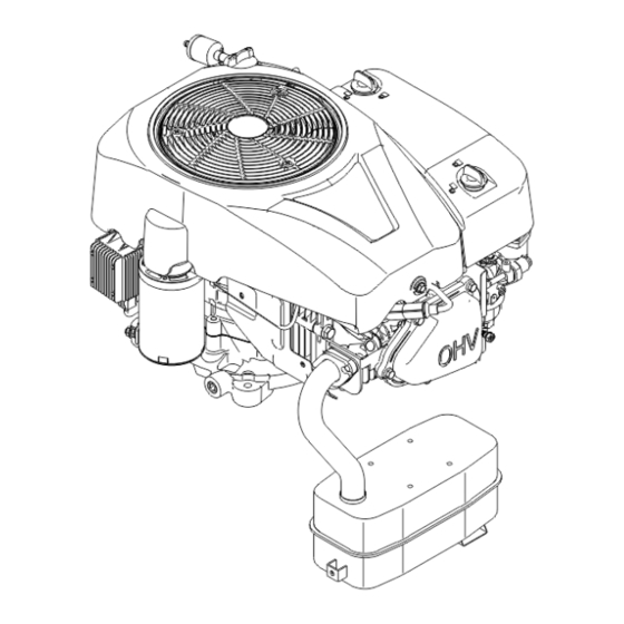
Page 5: Part I Introduction
Part I Introduction 1-1 Components of general-gasoline engine Engine outer cover Voltage regulator Spark plug Starter Spark plug cap motor components Engine dust cover filter Oil level gauge Gasoline pump component Fuel filter Secondary oil filter... -
Page 6: Parameters
1-2 Parameters Model RV550D Specification parameters Length*width*height 480*406*315 (mm) (no muffler) Net weight 32 kg Horizontal single-cylinder, four-stroke, Type of gasoline engine overhead valve (OHV) Air displacement 547 cm Cylinder diameter x stroke 94.5 mm × 78 mm Theoretical maximum power 12.2 kW/3,600 r/min Recommended service power 8.8 kw/2,700 r/min... - Page 7 Inner diameter of big end 38.010-38.022 38.066 Big-end oil-film clearance 0.030-0.055 0.12 Clearance of big end side 0.1-0.75 Crankshaft Outer diameter of crankshaft 37.967-37.98 37.92 0.15-0.20 Valve clearance Intake 0.15-0.20 Exhaust Outer diameter of 6.563-6.575 6.418 Intake valve stem 6.548-6.56 6.375 Air valve Exhaust...
-
Page 8: Part Ii Dimension And Torque
Part II Dimension and Torque 2-1 Dimensions of general-purpose gasoline engine... -
Page 9: Locations Of Mounting Holes
2-2 Locations of mounting holes 2-3 PTO installation drawing... -
Page 10: Torque Parameters
2-4 Torque parameters Fastening position Fastening part Torque (N·m) Oil drain plug 3/8-18NPTF 20 ± 2 Connecting rod bolt M8 × 38 16 ± 1.5 Mounting bolt of governor gear M6 × 14 10 ± 2 Closure bolt (special bolt) M8 ×... -
Page 11: Part Iii Maintenance
Part III Maintenance 3-1 Maintenance list 1st month Maintenance or 10 Every 3 Every 6 Every Every year period hours at months or months or time or 100 hours the first 20 hours 50 hours Item time √ Check-fill Gasoline √... -
Page 12: Oil
Oil capacity: RV550 1.5L SAE10W-40 is the recommended general-purpose oil at common temperatures; the oil with other stickiness could be used when the temperature in your area is within the range shown in the chart. -
Page 13: Air Filter
Replacement of oil: There is harmful substance in the waste oil, if the skin contact with the waste oil for a long time, it may lead to skin cancer. Clean your hands thoroughly with soap and water as soon as possible after contact with the waste oil. ... -
Page 14: Spark Plug
Paper filter Blast compressed air from inside or slightly knock it to remove the dust. It element shall be replaced in case of very dirty. Be careful not to let dust enter the carburetor when wiping off the air filter cover ... - Page 15 0.60~0.80 mm electrode Side e) In order to prevent disorderly thread, screw in the spark plug with hand, tighten it with special socket, and then tightly press the washer. f) If a new spark plug is installed, an additional 1/2 turn shall be tightened after pressing the washer. g) If a used spark plug is reinstalled, an additional 1/8~1/4 turn shall be tightened after pressing the washer.
-
Page 16: Adjustment Of Valve Clearance
3-5 Adjustment of valve clearance The valve clearance must be measured when the gasoline engine is cold. a) Remove the bolts (M6×16), cylinder head cover, gasket, spark plug cap and spark Cylinder head plug in turns cover gasket Spark plug Cylinder head cover Hexagon flange bolt... -
Page 17: Governor
lock with 10 mm wrench Locking torque: about 8 N·m~12 N·m g) Take out the 10 mm and 14 mm wrenches, measure the air valve clearance with the feeler gauge slightly; if the clearance is too large or small, repeat the steps c~f; h) Adjust the valve clearance of another air valve with the same method;... -
Page 18: Part Iv Disassembly And Maintenance
be done when using. Part IV Disassembly and Maintenance 4-1 Troubleshooting 4-1-1 Start difficulty Phenomenon Cause Remedy There is no fuel in fuel tank Refuel Clogged venthole of fuel tank cap Dredge Main measuring hole is Re-adjust or clean, blow through improperly adjusted or blocked Remove needle valve for repairing, Float needle hole is blocked... -
Page 19: Underpowered
Check valve clearance and valve Valve leakage tightness, repair when necessary If gasoline engine is still unable to be started, please send it to authorized dealer of the Company for overhaul. ⚫ Spark detection Ensure that there is no spilled fuel outside the gasoline engine and the spark plug is not soaked by fuel. -
Page 20: Unstable Speed
when it is Combustion-chamber deposit Clear carbon deposit serious Carbon deposit in the muffler and Clear carbon deposit exhaust pipe Blockage of air filter Clean filter element Leakage of air intake system Repair or replace Wear of piston, cylinder and piston Replace worn parts ring Poor... -
Page 21: Unable To Ignite
4-1-4 Unable to Ignite Phenomenon Cause Remedy Fuel used up Refuel Carburetor is clogged Check oil way and dredge it Fuel leakage of float Fuel supply Repair float needle valve chamber system Disassemble the float Needle valve is stuck chamber, and remedy the trouble Spark plug is broken through with carbon... -
Page 22: Abnormal Sound
4-1-6 Abnormal sound Phenomenon Cause Remedy Wear of piston, cylinder and piston ring Replace worn parts Wears of piston, cylinder and piston Knocking noise Replace worn parts ring Piston ring is broken Replace piston ring Excessive carbon deposit in combustion Clear carbon deposit Produce metal chamber... - Page 23 deflector and other components shall be removed in time to ensure normal cooling of the gasoline engine. 6) The operator shall be familiar with the working principle and structure of the gasoline engine, and understand how to operate emergency shut-down and all control components. Adhere to regular maintenance and service, and eliminate the fault found in time, and prohibit continuous operation of gasoline engine after the failure.
-
Page 24: Special Tools
使用前请仔细阅读使用说明书 使用时请勿触摸 使用时请远离火源 使用时请避免吸入废气 4-2-2 Special tools Tool name Application location·Remarks (I) Float height gauge Correction of intake and exhaust valve seat surface (II) Valve guide replacer Correction of intake and exhaust valve seat surface (III) Outer seat ring assembler Disassembly of flywheel (IV) Assembler handle (V) Inner seat ring assembler... -
Page 25: Disassembly Chart
4-3 Disassembly chart Gasoline engine Carburetor Flywheel Air filter Air director Starter Muffler Gasoline engine housing 4-4 general-purpose gasoline engine 4-4-1 Muffler a) Disassembly/assembly Air exhaust gasket Muffler Disassemble the muffler according to the above drawing In the process of long-term using, the muffler will produce the carbon deposit which causes a serious impact on the exhaust system. -
Page 26: Air Filter
When removing the carbon deposit inside the muffler, it is allowed to slightly knock with hammer and blow away with compressed air. If the muffler has water droplets and is seriously corroded, which increases the exhaust noise, it shall be replaced with a new one. Don't clean it with iron wire, or the sound proofing material might fall off, which will reduce the silencing performance. - Page 27 Knob Air filter housing Engine outer cover cover Air filter element combination Air filter intake pipe assembly Hexagon flange nut Air filter gasket b) Installation precautions Inspect the air filter gasket for damage before assembling, Pay attention to the installation direction, looking from the air filter side. ...
- Page 28 4-4-3 Governor Disassembly/assembly Serial Part name Serial Part name number number Crankcase gasket Flat washer Crankcase cover assembly Hexagon flange bolt Oil seal Pressure relief bolt Hexagon flange bolt Screen cover Speed control gear components Pressure relief valve spring Speed regulating core shaft press plate Steel ball Hexagon flange bolt Oil pump component...
-
Page 29: Carburetor
Serial Part name Serial Part name number number Speed regulating pull rod Throttle control combination Choke lever Hexagon flange bolt M6 * 16 Governor spring Hexagon flange bolt M6 * 30 Fixing bolt of speed regulating bracket Throttle return spring Speed regulating support assembly Clamp Hexagon flange nut M6... - Page 30 engine, overheating and even cause more serious damage. The gasoline is fed into the carburetor from the fuel tank and fuel filter. The fuel filter can filter out impurities mixed in the gasoline and oxides in the fuel tank. If the quality is defective, some impurities will fuel filter.
- Page 31 a) Disassembly and assembly of carburetor: Carburetor main body (clean thoroughly with compressed air Adjusting screw spring before installation) of idle mixing ratio Master nozzle Fuel feeding needle Main metering jet valve Float (After installation, press gently with Float pin fingers to check whether the float can move smoothly.) Float chamber seal gasket...
- Page 32 Main metering jet Clean thoroughly with compressed air O ring before assembling. O ring Clean thoroughly with compressed air before assembling, lightly lubricate the Idle metering jet O ring so that it can be easily installed into the Carburetor main body carburetor b) After cleaning the carburetor, restore the mixing ratio adjusting screw.
-
Page 33: Flywheel
4-4-5 Flywheel ① Disassembly: a) Clamp the flywheel by flywheel brake Flywheel brake available in the market, remove flywheel brake (M16). b) Disassemble the flywheel by flywheel puller available in the market Flywheel puller The flywheel shall not be hit by hammer ... -
Page 34: Ignition Coil Detection
d) Align four holes on rear side of the flywheel through four holes on the flywheel. Torque: 160±10 N.m Ignition coil Serial Part name number Flywheel nut Impeller gasket Impeller Flywheel assembly Charging coil combination Hexagon flange bolt M5 * 25 Hexagon flange bolt M6 * 25 Ignition coil Cross recessed pan head tapping screw... -
Page 35: Charging Coil Detection
The resistance of primary coil: 1.0-1.5 Ω (recommended value) (Secondary side) Remove the cap of spark plug, to connect one end of the tester to HV harness, and make contact between the other end and coil core, to measure resistance value on the secondary side of the coil. -
Page 36: Voltage Regulating Rectifier
4-4-8 Voltage regulating rectifier Test the continuity of each pair of wires The insulation resistance of each line shall be ≥ 20 mΩ After confirming that the parts are not damaged through above inspections, connect all wiring harnesses and detect the output voltage. As the detection requires starting the engine, this operation will be dangerous. -
Page 37: Cylinder Head/Valve
4-4-9 Cylinder head/valve Valve assembly Cylinder head gasket assembly Assembly of cylinder head Location pin Valve tappet Spark plug Cylinder head bolt Valve lifter assembly Hexagon flange bolt M8 * 32 Valve spring Valve spring seat Valve adjusting cap Valve gutter Oil deflector Exhaust valve rocker arm Valve spring retainer... - Page 38 Cylinder head Assembly: Before installation, remove carbon Locating pin (12 * 20) deposit in the combustion chamber, check the contact state of valve seat, and then measure the compression pressure before installation. Cylinder head cover gasket Cylinder head gasket Spark plug Cylinder head bolt (M10 ×...
- Page 39 ① OD of valve stem Use a micrometer to check the outer diameter of valve stem. If the diameter is lower than standard or exceeds the maintenance limit, or the valve surface has visible ablation or cracks, replace it with a new valve. Standard Maintenance limit Inlet: 6.563-6.575 mm...
- Page 40 If the ID of valve guide pipe is below the standard or exceeds the maintenance limit, replace cylinder head. Standard Maintenance limit 6.6-6.615 mm 6.662 mm Reamer: When reaming preciously valve guide with a reamer, be sure to be at room temperature to get good result.
- Page 41 remove carbon deposit out of Thoroughly combustion chamber and valve seat, and apply a thin layer of red lead powder on the surface of valve, or other adhesive Valve surface color paints easy to be wiped. Insert the valve and press the valve with effort a few times, but do not rotate the valve on the valve seat. If the valve seat is stained with paint, it indicates that it is in close contact with the valve;...
- Page 42 valve seat completed is within specified range. Standard Maintenance limit 1 mm 2.2 mm e) Slightly grind with by 45° grinder to remove any burr on the edge of valve seat. After reshaping the valve seat, check the width of valve seat. Use only the colorant on valve Valve cone face, to insert the valve and press the grinding...
-
Page 43: Crankshaft/Piston
4-4-10 Crankshaft/Piston Piston ring components Piston Connecting rod Crankshaft Piston pin Assembly: Be careful not to damage the oil seal during Snap ring of piston installation, and push it Connecting rod until the bearing contacts cover the crankshaft case. Connecting rod bolt Torque: 16.5 N·m Camshaft Balance... - Page 44 Manufacturer's mark ① Disassembly: 120° a) Piston Ring 1 Make manufacturer's mark face up Ring 2 when assembling. Be careful not to “▽” mark Oil ring assembly confuse the first ring with the second ring. Make sure that piston ring moves freely after assembling.
- Page 45 b) Connecting rod cover Align connecting rod with the edge of the connecting rod cover when installing. Alignment mark c) Oil seal: Apply lubricant to the edge of Replacer handle oil seal. Outer seat ring replacer Assemble oil seal into Oil seal 40×52×9 crankcase body by below tools.
- Page 46 Carbon deposit is accumulated on the top of piston and the edge of upper port of the cylinder. Carbon deposits shall be cleared up before the inspection. Soak the carbon deposit with kerosene first, and then remove it with a blunt scraper or metal brush. a) O.D.
- Page 47 Standard Service limit 0.02-0.07 mm 0.07 mm e) Closed gap of piston ring Piston ring Put piston ring horizontally into the cylinder, push the ring to working position with piston head, and then measure its opening clearance by thickness gauge. This clearance shall be neither too great, nor too small.
- Page 48 If it is below the criterion or exceeds the maintenance limit, replace the connecting rod. Standard Service limit 20.011-20.022 mm 20.022 mm b) Test the diameter of big end If it is below the criterion or exceeds the maintenance limit, replace the connecting rod.
- Page 49 camshaft. Standard Maintenance limit 19 mm (inlet)/19 mm (exhaust) 18.9116 mm (inlet)/18.9116 mm (exhaust) Inspect the outer diameter of the cam. When it is less than the service limit, replace the camshaft. Standard Maintenance limit 14.966-14.984 mm 14.916 mm Analysis on causes of camshaft wear and its impact on the performance of whole gasoline engine: The main cause for abnormal camshaft wear of the camshaft is poor lubrication, Factors...
- Page 50 Oil seal (It shall not be reused) Crankcase cover Crankcase assembly The main damage of timing gear is the wear of gear tooth, tooth face peeling or roughness, gear deflection, gear tooth breakage, etc. Due to the wear of gear teeth, the greater the meshing gap, the greater the noise.
-
Page 51: Electrical Schematic Diagram
4-5 Electrical schematic diagram...
Need help?
Do you have a question about the RV550 and is the answer not in the manual?
Questions and answers