Table of Contents
Advertisement
Quick Links
Advertisement
Table of Contents

Subscribe to Our Youtube Channel
Related Manuals for Rato R3000IS


Summary of Contents for Rato R3000IS
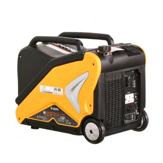
- Page 1 3.0KW INVERTER GENERATOR MAINTENANCE MANUAL...
- Page 2 This maintenance manual contents regulations which should comply to in daily maintenance and trouble removal on generator. Please make sure serviceman could read this manual anytime. This maintenance manual describes the correct maintaining methods. Any personal injury or death or equipment damage, which because ignorance on these regulations, our company would remove the responsibility.
- Page 3 SAFETY NOTICE Your human safety and property are very important as well as others .Please ready following safety notice in this manual and on generator decals, each safety notice has a symbol Failure to follow this instruction could result in extreme severe injury. Failure to follow this instruction might result in severe injury.
-
Page 4: Table Of Contents
CONTENTS ° GENERAL INFORMATION ................... 6 1-1Main Components ......................6 1-2General parameter ......................7 MAINTENANCE ......................9 2-1Maintenance table ......................9 2-2Engine oil ........................10 2-3Air cleaner ........................11 2-4Clean fuel strainer ....................... 12 2-5Spark arrestor ......................12 2-6Spark plug ........................13 2-7 Valve clearance adjustment .................. - Page 5 3-4Gasoline engine ......................26 3-4-1Starter recoil/fly wheel/ignition coil ..............26 3-4-2Carburetor ......................31 3-4-3Stepping motor ....................33 3-4-4Cylinder head ....................34 3-4-5Crankshaft/piston ..................... 41 3-5Generator ........................47 3-5-1Fuel tank ......................47 3-5-2Muffler ......................48 3-5-3Frame seat assy/Frame/Frequency converter ..........50 3-5-4Control panel ....................
-
Page 6: General Information
GENERAL INFORMATION 1-1 Main Components Hand bar Recoil starter Hand bar Control panel Left cover Cylinder head cover Air cleaner Wheel Fuel tank cap Oil dipstick Shroud Cushion... -
Page 7: 1-2General Parameter
1-2 General parameter Generator model R3000IS/R3000ISP Type Silent inverter generator Frequency /Hz 50Hz/60Hz Rated voltage /V 100V/120V/220V/230V/240V Max power /kVA Motor Rated power /kVA Power Factor Waveform deviation factor/% ≤%3 Noise (3/4 load) 65dB DC output / V-A 12V/8A Engine model... - Page 8 1-3 Repair standard Components Items Standard Limitation Max unload speed Gasoline 3600±100 Cylinder pressure engine 0.45~0.69/600rpm Cylinder Inner diameter 70~70.015 70.065 Piston skirt outer diameter 69.975~69.985 69.925 Piston-cylinder clearance 0.015~0.04 0.13 Inner diameter of piston pin hole Piston 18.002~18.008 18.018 Piston pin outer diameter 17.992~17.998 17.982...
-
Page 9: Maintenance
MAINTENANCE 2-1 Maintenance table Regular maintenance contributes to safety, economic, no malfunction and environmental protection. Exhaust contents toxic carbon monoxide, please stop the engine before maintenance. If you have to implement the maintenance when generator running, please make sure the working area is draughty. Regular maintenance tableV 20h or the first 100h or... -
Page 10: 2-2Engine Oil
2-2 Engine oil Put generator on horizontal plane. Assemble the cover, tighten bolts Loosen the bolts as marked, remove the Note Every time before use generator, cover. (Pull the cover back slightly and place it on horizontal plane, stop the engine then pull it up). -
Page 11: 2-3Air Cleaner
2-3 Air cleaner Dirty air cleaner will affects the air into carburetor. For reducing carburetor faulty, please maintain the air cleaner regularly (As maintenance table shows) and increase the maintenance frequency if generator used in dusty area. Use gasoline or inflammable solvent to clean air cleaner element could result in fire or explosion. -
Page 12: 2-4Clean Fuel Strainer
2-4 Clean fuel strainer Fuel strainer is designed for preventing dust into carburetor. If generator isn’t used for a long time, please clean fuel strainer after empty fuel tank. 1) Remove the cover (refer to air cleaner maintenance step 1), empty fuel tank. 2) Squeeze clipSTpull it down, and pull the fuel hoseT out, which connected to fuel tank. -
Page 13: 2-6Spark Plug
2-6 Spark plug Adjusting the gap of spark plug, you can bend the electrode slightly to keep the Use incorrect model or caloricity of spark gap between 0.70-0.80 (mm). arrestor could decrease engine performance and damage it. Side If keep engine running, spark plug and muffler electrode 0.7-0.8mm Wire brush... -
Page 14: 2-7 Valve Clearance Adjustment
2-7 Valve clearance adjustment There always be clearance between valve end and its transmitted parts, in case of contraction which would effect engine work. If the clearance is in excess, it would result in higher back- pressure and higher noise (abnormal noise from valve) and decrease engine performance. If the clearance is insufficient, it would make the valve can’t be sealed totally, which might result in abnormal performance or burning the working surface of relevant parts of valve. - Page 15 Ÿ Adjust valve clearance. Screwdriver 56 J: Wrench 56 J: Adjustment steps: loosen the tighten bolt, turn the adjustment nut to a proper position, and tighten the adjustment nut. Intake 0.05~0.10mm Valve clearance Exhaust 0.05~0.10mm Adjust the bolt Valve clearance Tighten Decrease Loosen...
-
Page 16: Failure Prediction And Repair
Part 3 Trouble determine and maintenance 3-1 Trouble determine 3-1-1 Start-up difficult Phenomenon Causes Methods of elimination No fuel oil in the oil tank Add fuel oil The vent hole on the oil tank Evacuate the blocking is blocked The main metering jet is Poor flow Re-adjust or clean, blow open improperly adjusted or... - Page 17 phenomenon Causes Methods of elimination Piston ring wearing limit Replace with new piston ring Piston ring break off replace Cementation of the piston Clear away the carbon deposit ring Spark plug gasket not Installed gasket and tighten it installed or not tightened Cylinder Fuel ignition...
-
Page 18: 3-1-2Power Insufficient
3-1-2 Underpower Phenomenon Causes Methods of elimination There is air in the oil line or the oil line Drain the air, clearing the oil line is blocked Improper adjustment of the main Re-adjust the main metering jet metering jet The needle valve opening and the main Fuel oil metering jet in the carburetor are Cleaning, blowing open... -
Page 19: 3-1-3Speed Unstable
3-1-3 Unstable speed Phenomenon Causes Methods of elimination The piston, cylinder and piston ring wear too Replace the wearing parts seriously Tapping sound The piston pin and the pin hole wear too Replace the piston or the of the generator seriously piston pin The small end of the connecting rod wears... -
Page 20: 3-1-5Oil Overheating
The side electrode of the spark Replace the spark plug, and plug falls off eliminate the stuff that falls off The high-voltage cable falls off replace it The ignition coil will breakthrough and cause short Replace the motor stator circuit The stopping line falls on the Find out the short circuit point and machine... -
Page 21: 3-1-7No Dc Output
Clearing away the Too much combustion-chamber deposit deposit Metallic tapping The fuel marking No. is wrong Replacing the fuel oil sound at explosion Check the cause and Overheat of the generator eliminate it Improper adjustment of the valve Re-adjust the valve clearance clearance Others The connection between the flywheel and the... -
Page 22: 3-1-9Indicator Light Judgment
3-1-9 Indicator flashes 1. Green light on: it means work, generator output; 2. Green light on, red light flashing: overload, generator output 3. Green light off, the red light flash once, after the interval 3S flash repeat: represents the front end of generatrix voltage is too low, no generator output;... -
Page 23: 3-2Repair Preparation
3-2 Preparation before maintenance 3-2-1 Safety factors Warning If the following precautions are not observed, the warranty of generator will be invalid and generator may be damaged or people may be injured. Therefore users should be especially careful of the following precautions before using generator: 1SConnecting the load strictly following manual on its rating plate;... -
Page 24: 3-2-2Special Tools
Special tools ·fu Name of Tool Using for·Remarks t i o c t i yoa h Valve guide replacer Removal and installation Valve guide vw ny Outer race assembler Assemble ball bearing mrTh Handle of assembler Assembler fit on the handle, fix on bearing vw n s Inner race assembler Ball bearing, timing gear assembly. -
Page 25: 3-3Disassemble Diagram
3-3 Disassembly Diagram Lift & right Muffler side 3 in 1 knob Cover plate cover Panel Panel bed Lift & right Inverter shell Fuel tank Baseplate Power motor Muffler wind Fly wheel Muffler assembly scooper filter Motor wind assembly Trigger scooper Carburetor Wind... -
Page 26: 3-4Gasoline Engine
3-4 Engine 3-4-1 Recoil Starter/flywheel/ Ignition Coil A A I D :I:F BOLT wind scooper high pressure pack M6x14 BOLT Recoil starter parts Oil seal GIG A I IG D M6x10 B A F GF B B A: Oil sensor Bolt M6x60 Motor parts Disassembling... - Page 27 Ÿ Recoil starter Ÿ NOTE: Be careful when you disassemble, do not make the starter coil spring pop up, please take on the gloves when operating Ÿ Be sure the rope without break or wear before installing. .G: BF : F Driven CAM Compression spring Check the rope if there is...
- Page 28 b. Knotting on the end of the rope, and then the other end of the rope pull hole some wear out. And then pull on the rope plate coil five laps in counterclockwise direction. Let the start rope through the starter cap hole, in the department to make a pull rope "8"Knot.
- Page 29 Charge Coil Put the tester (follow the picture) with charge coil, to test the charge coil resistance value. Charge coil resistance value: 350Ω 3) Motor Parts check...
- Page 30 Main winding/Power winding/DC winding DC voltage output, check whether DC over-current protectors tripping and DC socket is damaged.If damaged, replace the socket. No voltage output, check whether the AC socket is damaged.If damaged, replace the socket. Check whether there is voltage between motor stator power windings.If there are voltage, replace the inverter.If there is no voltage, the change of the stator.
-
Page 31: 3-4-2Carburetor
3-4-2Carburetor Disassemble the Carburetor Bolt: M3×5 2 4G GI GM I Torque: (1~1.5) N•m Speed governing Bolt: M5×12 2 torque: 4G GI L GI .: D 0L D I:BF I :I LI GI 3 BF 1: C Heat pad Gasoline is by the fuel tank through the fuel filter into the carburetor, fuel filter can filter out the impurities and the gasoline oxide of the tank .If the quality is flawed, there will be some impurities through fuel filter into the carburetor. - Page 32 To clean the carburetor should be clean with specific area. Firstly, to wipe carburetor surface, the cleaning of internal parts can use special carburetor cleaner or industry .Except the impurities, should pay attention to clean the gasoline gum on the surface of the parts .The parts need with compressed air blowing off, cloth or paper will not be used to wipe ,in case of pollution again.
-
Page 33: 3-4-3Stepping Motor
3) Carburetor Installation a) Check the float valve and float valve seat before installation. J6 J: b) Use compressed air to clean before installation. main air bleed c) Use compressed air to clean before installation. 06 C d) Use compressed air to clean and Lubricate o-ring before installation. 1 F C .: G 6F7IF: F 7 9L... -
Page 34: 3-4-4Cylinder Head
3-4-4Cylinder Head 1) Remove/Installation .PDBF I A : GD 4) ( side cylinder Unscrew and tighten bolts should epicranium, on other side pick up be according to the cross. in the tank cover plate of vertical .PDBF I A : GM I Torque value 12~14 N·m I : ABF... - Page 35 Valve adjusting bolt Spark plug Valve rocker .A C B A I B :FP Clean the spark plug before Check if there is any installation. damagement before BF :DD: BGF N·m installation,esprcially the Torque value 25-28 hole and tappet assembly. Locked nut Spring Oil drip pan...
- Page 36 2SInspection/Maintenance/Repairing: ①Valve stem diameter Using micrometer to check if the valve stem diameter is lower than the standard limit, visible to the naked eye , more maintenance gas appearance have ablation or crack. With above situations ,you’d better to change with the new one. Standard Maintenance Limit 5.468~5.48mm inS...
- Page 37 Replacement: a) To replace the valve guide into the freezer frozen 1 hour or so b) Use the valve guide puller to remove the valve guide pipe from combustion chamber side. Noted When remove the valve guide, do not damage the cylinder head. c) Put the new valve guide pipe from the cylinder head valve spring 56 J: I 9: I :F...
- Page 38 d) Check the clearance between I :F the catheter and the valve stem e) Clearance between the valve stem and valve guide: the valve -CG 6 6 guide inner diameter minus the valve guide stem. If the clearance between the valve stem and catheter values is out of maintenance limit, you should decide to replace a new catheter to clearance within the limit of maintenance, if so, replace the valve guide and stick ground valve guide.
- Page 39 Tool Valve grinding machine ,F 9 C 6C9 : C 6 : J6 J:V " I 6 : J6 J:V " C 6 : J6 J:V I 6 : J6 J:V d) Using 32 ° to 45 ° mill to reduce and adjust the valve seat, to let it contact with the valve cone parts.
- Page 40 gSOn the valve seat's cone daub abrasives, use valve grinding tool rotation to the valve seat to get up to speed. ,F C9 C hSCheck valve clearance after installation.
-
Page 41: 3-4-5Crankshaft/Piston
3-4-5 Crankshaft/Piston GD 4 O Assembly should preloaded, tighten it by triangle. .GFF IG Painting engine oil on the Check if there any wears before assemble. inside of connecting rod. PGL : 6B GF 6F G I 9 7 GI7 :... - Page 42 ① Installation " a) Piston Ÿ Use supplier mark up during FG F C installation. Be careful not to put first ring C9 F C confused with second ring (a ring with O P 6F 1 F C chrome plating) Ÿ...
- Page 43 ②Detection of piston Check the contact situation, the piston and cylinder top ring groove defect, ablation and crack etc. If the damage is serious, you should use the new one. Remove the carbon deposit The carbon deposit located on the top of the piston and cylinder flowing edge part. You should be cleared away before testing carbon deposit.
- Page 44 a) Piston- Cylinder gap The biggest diameter of the cylinder minus the piston skirt diameter . Note Be tested the gap before and after repairing. When you checking, the inverted piston should be in the cylinder, put the appropriate thickness gauge on the pressure surface between the cylinder wall and piston skirt, and then take out feeler gauge, if you feel some certain resistance, but you also can smooth out, that is clearance between the piston and cylinder.
- Page 45 ③ Detect the connecting rod If the connecting rod bending, distortion, or cracking etc., you should the replacement of new parts. a) Detection of small diameter If lower than the standard limit or out of using limit, Replace with new one. Standard Using limit 18.011~18.022 mm...
- Page 46 Ÿ Check the camshaft neck diameter ,if it is less than the standard ,you should replace camshaft. Standard Maintenance limit 14.166~14.184 mm Using with the standard Wear reasons and affect for the engine performance: Camshaft is wearing and tearing, the main reason is poor lubrication, such as low oil viscosity, impurities, small amount of circulating oil etc, cannot make the camshaft surface full oil film which lead to the camshaft with high speed dry friction state of the surface wear serious.
-
Page 47: 3-5Generator
3-5 Generator 3-5-1 Fuel tank Cap,Fuel Tank Assembly To ensure a clean and not blocked vent. If necessary, use compressed air to clean Table oil hole fbdh Assembly .A C DG BF GI A F BF :DD Bolt M6X20 Assembly To clear the bottom of the accumulated dirt... -
Page 48: 3-5-2Muffler
3-5-2 Muffler Bolt M6x16 Bolt M8x16 Nut M8 Plate,Muff Insulation Plate, muffler Shrou Gasket Muffler Assembly Muffler gasket easy damaged. Bolt M8x20 Should be replaced after Bolt M6x12 each disassembly As shown above dissassemble muffler Muffler long-term use can cause carbon deposition, to the exhaust system caused a serious impact. - Page 49 Ÿ Muffler will heat. Keep the gasoline engine away from passer and out reach of children. Ÿ During the gasoline engine is running, do not place any flammable materials near the exhaust port.
-
Page 50: 3-5-3Frame Seat Assy/Frame/Frequency Converter
3-5-3 Bottom of Frame/Frame/Inverter Removing and installingV Bolt M6x12 Plate,Frame Frame Parts CG 6 C Screw M4x12 To clarify left and right frame member, Click on the Install dashed arrows and bottom of the rack chassis combination dashed Nut M8 Bolt M8x40 Plate,Cran kcase... - Page 51 1) Checking Inverter Part Inverters need to be detected in the generator operating state Checking the wire on the inverter whether have color change.The upper inverter filled resin whether have blister-like projections.Checking all electrical components on the inverter, connectors and wiring no visible color change or damaged .
- Page 52 Sensitive Switch When spring is in the bounce state sheet, with an ohmmeter measure resistance between two output terminals. If the resistance is zero, replace the micro switch. When the spring plate in a compressed state, with an ohmmeter measure resistance between two output terminals.
-
Page 53: 3-5-4Control Panel
3-5-4 Control Panel Components Remove and Equipped Switch, Fuel 3in1 Checking the leakage Switch after installing Circuit Control From Left to protecter panel Right : Oil Alert, Over load Fuel Engergy Alert,AC On Pipe Indicat Save Socket Wire,Control Panel Self-tapping If not necessary Terminal,Gro please... - Page 54 Checking Combination Switch When the combination switch in each position, checking the ignition circuit, fuel switch, choke switch status Close switch is "OFF", the ignition circuit is turned off, namely two micro switch output terminal is turned on, the ignition grounding; oil switch is turned off, the engine would not run.
- Page 55 Fault indicator (Red) Fault indicator is on, the detected output of the generator is connected to the electrical equipment has been overloaded, resulting in a Inverter overheating, or AC in pressure. In this case, AC protection work to stop this generator, in order to protect the generator and electrical equipment connected.
-
Page 56: 3-5-5Appearance Diagram
3-5-5 Exterior Assembly Bolt M6x20 Beam rotatio Screw Rotati ng arm Cover Decorati Plate ,RH Cover ve plates Muffler Bolt M6x12 Side Self Tapping Cover,Muff Rubbber Gasket.Muffler Srew Front Decorati Cover wheel Housing ve plates Plate FR Housing Cover Plate,LH... -
Page 57: Wire Connecting Diagram
FOURTH PART Wiring diagram 4-1 Wiring diagram... - Page 58 Attachment Torque Sheet Torque N Item No. Items Thread Size Grade · Shroud,Muffler ST4.8×16 4.8-A 4±1 Guide plate,Pull Rope M5×12 4.8-A 4±1 M6×19 Housing,RH LH 8.8-B 9±1 Side cover,Muffler M5×16 4.8-A 4±1 Fuel Switch M6×12 8.8-B 10±2 Support,Inverter 9±1 Inverter M6×12 8.8-A 9±1...
- Page 59 Standard torque parameters Torque N Fastening Parts Thread Size · 5mm SCREW,BOLT 5±1 6mm SCREW,BOLT 10±2 8mm SCREW,BOLT 20±2 10mm SCREW,BOLT 32±2 12mm SCREW,BOLT 55±5 4mm SCREW 2±1 5mm SCREW 4±1 SCREW,BOLT 6mm SCREW 8±2 5mm Flange bolts 5±1 6mm SCREW 8±2 5mm Flange bolts 5±1...
Need help?
Do you have a question about the R3000IS and is the answer not in the manual?
Questions and answers
Regarding a inverter generator distributed by patron with a model number of R3000 ISP-2 with a date of manufacturer of the 10th month of 2021… I work for a rental company in Canada and as you can see by the image enclosed with this email, I **** attempting to test these units with a standard 110 V receptacle tester and the result I **** receiving are confusing… I have tested multiple generators like this and they all give the same reading. I have also tested multiple receptacle testers, and they all give the same reading… I assume this has something to do with the inverter… Because using multimeter, I cannot detect any problems. The unit also low test correctly. However, my customers have electricians testing them and telling me that they are faulty. Please confirm that this reading is normal and not an issue so I can send some sort of confirmation confirmation to my customers.