Advertisement
Quick Links
Advertisement

Related Manuals for Rato R1000I


Summary of Contents for Rato R1000I
- Page 1 R1000I Maintenance Manual Chongqing RATO Technology Co., Ltd.
- Page 2 This Manual contains the specifications to be in compliance with for routine service and maintenance as well as troubleshooting of general purpose generator. Make sure that maintenance personnel of this equipment can refer to this Manual at any time. This Manual describes correct methods to service this equipment. Our Company shall not bear liability for neither personal injury nor equipment damage caused by ignoring these regulations.
-
Page 3: Safety Warning
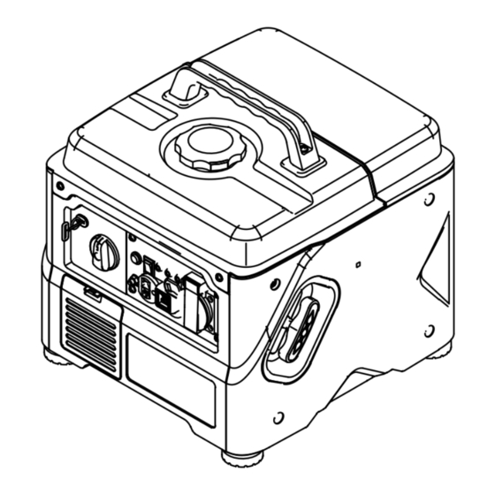
Safety Warning Your personal and property security and that of others are very important. Please read carefully our three vital safety warnings written in the maintenance manual and in the decal of the generator, with the symbol preceding each one. Details are as follows: If you do not follow the instructions, you will be seriously injured. - Page 4 Part 1 Introduction 1-1 Components of general purpose generator Fuel tank cap Fuel tank Right appearance Control panel cover plate Starting rope handle Cover gasket of air filter housing Panel seat Handle Side shield of muffler Left appearance cover plate...
- Page 5 1-2 Parameter Item R1000i Gasoline engine R56-i Type of gasoline engine Four-stroke, valve-on-the-side, single cylinder Displacement (cc) Ignition system Capacitor discharge ignition (CDI) Gasoline engine Volume of fuel tank (L) Continuous working period (hr) Engine oil capacity (L) 0.28 Voltage (DC) (V)
- Page 7 1- 3 Repair Standard Parts Item Standard Use limit 4800± 100 Gasoline Maximum unoad speed Cylinder pressure 700~900Kpa/1400rpm engine 45~45.015 45.065 Cylinder I.D. of cylinder Piston skirt outer diameter 44.97~44.99 44.92 Piston - cylinder clearance 0.01~0.045 0.13 Piston I.D. of piston pinhole 10.002~10.008 10.018 O.D.
- Page 8 0.6-0.8 Spark plug Clearance 10kΩ Spark plug cap resistance...
- Page 9 1-4 size...
- Page 10 Part II Maintenance 2-1 Service List Good maintenance and service is the best guarantee for safe, economical and zero-failure operation. It also contributes to environmental protection. The exhaust gas of the generator contains toxic carbon monoxide, please stop the gasoline engine for maintenance. If you have to implement the maintenance when generator running, please make sure the working area is draughty.
- Page 11 2-2 Service and Maintenance 2-2-1 Engine oil ⚫ After allowing gasoline engine to warm up (Startup gasoline engine to run at no-load for 10 minutes), let it stand for another 10 minutes, only that can ensure to drain engine oil quickly and completely. Remove oil dipstick.
- Page 12 2-2-2 Air filter Getting dirty of air filter may prevent air from flowing into the carburetor. In order to prevent carburetor failure, the air filter shall maintained regularly. (see Maintenance List for the cycle, and see the figure below for the method). If being used in dusty environment, it shall be maintained more frequently.
- Page 13 2. Visually inspect the insulator of spark plug for damage. If the insulator is damaged, replace it with a new one If the electrode has carbon deposition, clean it by wire brush. Measure the gap of spark plug with a thickness gauge Proper gap shall be 0.70 ~ 0.80mm.
- Page 14 Part 3 Failure Determination and Repair Preparation 3-1 Safety Factors Failure to observe the following precautions will result in the invalidation of the warranty provided with the generator and may damage the generator or cause personal injury. Therefore, before using the generator, Operators should pay special attention to the following points: 1.
-
Page 15: Fault Diagnosis
3-2 Fault Diagnosis Testing spark plug Ignition system Check the ignition coil Difficult starting Oil protection test Fuel system Starting and Oil Line Test Inability to start flameout Carburetor Starting rebound Valve Train Cylinder pressure test Abnormal sound inside the box Operating Valve Clearance Test abnormal... - Page 16 Dynamical Power problem Maintenanc Inability to start Control Whole panel machine problem Socket without Magneto output output No DC output Frame Appearance parts Abnormal Voltage too high output or too low Operating abnormal sound...
-
Page 17: Maintenance Tools
3-3 Maintenance Tools Tool Designation Model Use Position T-sleeve 5mm-12mm Screwdriver Flat and cross clamp forceps nose plier Thumb forceps Hammer Vernier caliper 100MM Inside 100MM micrometer Outside 100MM micrometer Multimeter... - Page 18 3-4 Disassembly 3-4-1 Disassembly graph Control panel Muffler Inverter Chassis Frame Damping Pad Hand starting Magneto Engine components...
- Page 19 Part 4 Maintenance 4-1 fuel tank/handle tube Cross recess head screw Handle Fuel tank cap Fuel filter screen Self-tapping screw Fuel tank Fuel cock set Fuel tank Mounting precautions Before the Assembly, inspect first whether the vent hole of fuel tank cover is clogged. ...
- Page 20 4-2 Hand starting components / motor /air filter Magneto stator assembly Hexagon flange bolt M5*28 Magneto Rotor Shell Assembly Hexagon flange bolt M6*12 Air filter element Air filter housing co Hexagon nut with fla mpeller Starter Recoil Assembly Hand starting components Drive guide plate Sprin Tightening screw...
- Page 21 Put the reset spring into the seat ring cover, the hook and aligned with the rope tray groove, then assemble the seat ring cover onto the pull rope tray. Apply grease on the claw of starter cover, mount while turning to the left, to make the hook inside reset spring hook onto the claw of starter cover.
- Page 22 Testing of resistance value of motor winding Ignition winding U, V, W three-phase output cable Grounding Control Winding DC winding Brown Blue White White Resistance value Winding name Wire color Resistance value Brown - brown (7.75±0.8)Ω Main winding Brown - brown (7.75±0.8)Ω...
- Page 23 4-3 Control Panel / Air Filter Inverter Hexagon flange bolt M5*35 Clip nut Control Panel Assembly...
- Page 24 Power socket assembly Overcurrent protector Indicator Choke valve lever Knob Earthing terminal assembly DC socket assembly Control panel components shown in the figure above are only standardized model of our Company. The control panel will be adjusted slightly according to specific requirements. Therefore, your real generator may be a little different from the model shown in the figure above.
- Page 25 the converter is replaced. 1. Frequency converter Frequency converter Testion should be carried out under the working state of the generators, such operation should not be conducted except by professionals. ⚫ Check that there is no color change in the wires on the converter, no blister protrusions on the resin filled on the converter, and no visible color change or damage to all...
- Page 26 automatically turns to the "OFF" position. Rectifier bridge When operating the generator again, press the DC switch to the "ON" position. ⚫ Check the continuity between the DC circuit Multimeter breaker terminals with a multimeter. The circuit breaker button should be turned on when pressed.
- Page 27 Insert the screwdriver into the slot as shown below and press down gently. 8. Anti-detaching Socket ⚫ Generally there is no problem with DC socket. If there is no DC output, generally it’s mainly to check the conduction, secondly to check if there is any breakage or not.
- Page 28 Non-conducted Conducted If it does not conform to the above conductivity, Yellow Black /Grey please replace the switch Assembly. Gasoline engine switch Remove the wire of switch terminal, to test the resistance of various terminals by ohmmeter as shown in the figure Breaker Protector When the protector is pressed down, it shall be in conducting state.
- Page 29 Power outlet Generally there is no problem with DC socket. If there is no DC output, generally it’s mainly to check the conduction, secondly to check if there is any breakage or not. Control panel harness Remove wiring harness from the panel, rectifier bridge and frequency converter.
- Page 30 4-4 Muffler Hexagon nut Muffler parts Side shield of muffler Exhaust port seal gasket Side shield of muffler Self-tapping screw The muffler will heat, please set this gasoline engine in the place where passers and children are unable to reach. When the gasoline engine is running, be sure not to place any combustible article near the exhaust port.
- Page 31 4-5 Power/Chassis Engine Chassis compone Rack connecting pipe Power fixing bottom plate Right appearance cover plate Chassis component Cushioning rubber pad support Rack mount Hexagon flange bolt M6 *12 Left appearance cover plate Self-tapping scre...
- Page 32 4-6 Carburetor Screw M3 × 5 (2) Torque: (1 ~ 1.5) N • Stepping Motor Protection Cover Speed stepping motor Screw M5 × 12 (2) Torque: (1.5 ~ 2.5N.m) Mounting bracket for stepping motor Cable-stayed plate C hoke valve bracket *Fuel screen Refer Maintenance List...
- Page 33 Damper combination Throttle Carburetor assembly main body Assembling: Main Blow in compressed air first, nozzle remove dirt from the internal passages, and then install. Assembling: Blow in compressed air first to clean away the dirt in the channel, and then mount it. Needle valve Assembling: First check the end wear and spring action...
- Page 34 Before installing the carburetor, the oil drain bolt must be loosened and the fuel Float valve inside must be drained. No fire and smoke. Float a) Assembly valve seat Before assembly, inspect the float valve, float valve seat and float spring for wear. Damaged Normal Main orifice nozzle Thoroughly clean with compressed air before...
-
Page 35: Cylinder Head
4-7 Cylinder head Spark plug Assembly / disassembly: The loosening and fastening of the bolts should be carried out in a crisscross manner. Stud bolt Torque value: 12 ~ 14 N.m Seal gasket of cylinder head Cylinder head cover Cylinder head assembly Stud bolt Assembling: carbon... - Page 36 Exhaust valve Intake valve Assembling: Assembling: It should be confirmed whether the valve shall cone surface is defective or not, confused. then installation Be careful when installing and performed. do not injure the valve stem. Valve spring seat Tappet assembly Assembling: Oil shield It should be confirmed that...
-
Page 37: Air Valve
3. Valve spring seat ring Slide the front end of the valve stem across the centerbore of the spring seat ring and remove it. If the cylinder head is installed on the cylinder, the spring seat ring may fall into the crankcase body and care should be taken. - Page 38 4-8 Crank-link Mechanism / Valve Mechanism Hexagon flange bolt M6 * 20 Assembling: When assembling, pre-tighten first, and tighten according to the triangular cross mode Oil seal Crankcase cover Assembling: Check wear Crankshaft before assembly. Deep groove ball bearing component Timing driving gear Crankcase body assembly...
- Page 39 Piston Piston skirt outer diameter Measure the OD of the piston skirt with an OD micrometer, to replace it if it exceeds the service limit. Standard Use limit See Table 1-3 See Table 1-3 The clearance of Piston Pin Hole and Piston Pin Use the inside micrometer and the outside micrometer to measure the inner diameter of the piston pin seat hole and the outer diameter of the...
- Page 40 Closure clearance of piston ring Piston ring Place the piston ring horizontally into the cylinder, push the ring with the piston head to the working position, and then measure the opening gap with a thickness gauge. If the gap of the ring opening is small, the opening can be filed with a fine flat file.
- Page 41 Connecting rod Measuring inner diameter of small end If it is below the criterion or exceeds the maintenance limit, replace the connecting rod. Standard Use limit See Table 1-3 See Table 1-3 Test the I.D. of the big end If it is below the criterion or exceeds the maintenance limit, replace the connecting rod.
- Page 42 Scale of plastic Radially place plastic feeler feeler gauge Plastic feeler gauge gauge Remove connecting rod cap, to measure by plastic feeler gauge. If bearing bush clearance exceeds maintenance limit, the connecting rod shall be replaced and the clearance shall be measured again.
- Page 43 Align the crankshaft with balance shaft (R5000 and R8000) Drive wheel Balancer of crankshaft balancer Main damage of timing gear is the wear of gear tooth, tooth face peeling or roughness, gear deflection, gear tooth breakage, etc. Due to the wear of gear teeth, the greater the meshing gap, the greater the noise.
- Page 44 Part V Attachments 5-1 Circuit Diagram Main winding 1 Inverter Winding of inverter power supply DC winding Commutating voltage-stabilizing module Power supply of ignition Triggering signal Integrated ignitor Throttle stepping Spark plug motor...
- Page 45 5-3 List of Vulnerable Parts Part name Remarks Carburetor components Common failure Hand starting components Starting guy wire Spark plug Air filter element Governor gear assembly Governor bonnet Air intake gasket Carburetor seal gasket Air filter gasket Seal gasket of cylinder head cover Seal gasket of cylinder head Oil seal Seal gasket of crankcase...
- Page 46 5.4 Standard Torque Fastening parts Thread specification Torque (N.m) 5 mm bolts, nuts 4.5-6 6 mm bolts, nuts 8-12 8 mm bolts, nuts 18-25 10 mm bolts, nuts 29-34 12 mm bolts, nuts 49-59 4mm Screw 1.5-2.6 5mm Screw 3.5-5 Bolt, nut 6mm Screw 7-11...
- Page 47 Chongqing RATO Technology Co., Ltd. Add: Block B,Shuangfu Industrial Park, Jiangjin District, Chongqing, China Service hotline:400-681-9981 Fax: 023-85553450 Postcode:402247 URL: www.rato.cc E-mail: ratoservice@rato.cc (service advisory) parts@rato.cc (parts order)
Need help?
Do you have a question about the R1000I and is the answer not in the manual?
Questions and answers