
Subscribe to Our Youtube Channel
Related Manuals for Intersurgical StarMed StarVENT 2


Summary of Contents for Intersurgical StarMed StarVENT 2
- Page 1 StarVENT 2 - Miscelatore aria-O pag. 3 StarVENT 2 StarVENT 2 - Air-O blender page 19...
-
Page 3: Table Of Contents
StarVENT 2 Miscelatore aria-O Istruzioni per l’uso INDICE DESCRIZIONE PRODOTTO................2 2 INFORMAZIONI GENERALI ................. 3 Fabbricante / assistenza tecnica ..............3 Garanzia limitata....................3 Dichiarazione di conformità ................3 Contenuto dell’imballo ..................4 3 INTRODUZIONE .................... 4 Destinazione d’uso ................... 5 Limiti di impiego .................... -
Page 4: Descrizione Prodotto
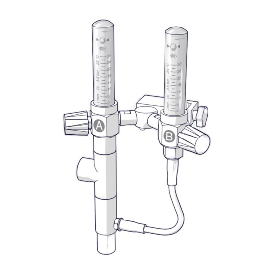
DESCRIZIONE PRODOTTO DESCRIZIONE PRODOTTO DESCRIZIONE PRODOTTO INFO Le immagini per il presente capitolo sono contenute nella sezione rappresentata da questa icona. Rif. Descrizione Flussimetro A - O principale (30 lt/mim.) Flussimetro B - O addizionale (30 lt/mim.) Manopola rubinetto di regolazione O Manopola rubinetto di regolazione O Ingesso aria Connessione all’interfaccia paziente (22 mm) -
Page 5: Informazioni Generali
INFORMAZIONI GENERALI INFORMAZIONI GENERALI INFORMAZIONI GENERALI 2.1 Fabbricante / assistenza tecnica Intersurgical S.p.A Via Morandi, 12 - 41037 Mirandola (MO) Tel: +39.535.610131 fax: +39.535.610310 info@intersurgical.it www.intersurgical.it 2.2 Garanzia limitata Le apparecchiature prodotte a brand StarMed vengono garantite per periodi di 2 anni dalla data di acquisto ed esclusivamente contro difetti di fabbricazione e materiali, purché... -
Page 6: Contenuto Dell'imballo
INTRODUZIONE INTRODUZIONE 2.4 Contenuto dell’imballo INFO Le immagini per il presente capitolo sono contenute nella sezione rappresentata da questa icona. Il contenuto dell’imballo è elencato nella sezione dedicata. INTRODUZIONE AVVERTENZA! Indicazioni Importanti di sicurezza: Il Fabbricante declina ogni responsabilità derivata •... -
Page 7: Destinazione D'uso
INTRODUZIONE INTRODUZIONE INFO Le istruzioni indicano come ottenere le diverse combinazioni di FiO2 e flusso al variare della Peep. ATTENZIONE La stretta osservanza delle indicazioni riportate sulle seguenti istruzioni d’uso garantisce il mantenimento delle prestazioni del dispositivo (vedere paragrafo “2.2 Garanzia limitata”). Il dispositivo è... -
Page 8: Controindicazioni
INTRODUZIONE INTRODUZIONE 3.3 Controindicazioni Con casco e/o maschera: • coma; • paziente non collaborante; • arresto cardiaco: • instabilità emodinamica • recenti interventi esofagei e gastro-chirurgici; • grave sanguinamento dell’alto tratto digerente; • ostruzione delle alte vie aeree; • pneumotorace. Solo con maschera: •... -
Page 9: Specifiche Tecniche
SPECIFICHE TECNICHE SPECIFICHE TECNICHE SPECIFICHE TECNICHE Tipo di gas erogabile Ossigeno in bombola o di impianti di distribuzione dell’ospedale. Condizioni ambientali di funzionamento Temp.: +5 2°C / +35 5°C Condizioni ambientali di stoccaggio e Temp.: - 40~2°C / +60 5°C e umidità relativa da trasporto 40% a 70% Ingombri (cm circa) -
Page 10: Installazione E Procedura Di Utilizzo
INSTALLAZIONE E PROCEDURA DI UTILIZZO INSTALLAZIONE E PROCEDURA DI UTILIZZO INFO I valori riportati sono riferibili all’impiego di circuiti ventilatori adulti a parete interna liscia di lunghezza 250 cm. Per tale ragione i valori di rendimento riportati nelle presenti istruzioni sono da considerarsi semplici indicazioni approssimative durante l’impiego di circuiti diversi da quello dichiarato. - Page 11 INSTALLAZIONE E PROCEDURA DI UTILIZZO INSTALLAZIONE E PROCEDURA DI UTILIZZO Fissare il dispositivo alla piantana/barra. I flussimetri devono essere posizionati in verticale per garantire il valore di accuratezza dichiarato (figura 1). Assicurarsi di aver fissato correttamente il morsetto (9) (figura 2). Verificare che i rubinetti dei flussimetri A e B siano completamente chiusi agendo sulle manopole (3 - 4) (figura 3).
- Page 12 INSTALLAZIONE E PROCEDURA DI UTILIZZO INSTALLAZIONE E PROCEDURA DI UTILIZZO Dopo aver controllato il corretto funzionamento è possibile collegare il dispositivo di interfaccia macchina/paziente (casco, maschera) e procedere alla ventilazione CPAP. AVVERTENZA! Non applicare mai la maschera e il casco al paziente prima di aver messo in funzione il generatore di flusso.
-
Page 13: Tabelle Dei Valori
TABELLE DEI VALORI TABELLE DEI VALORI TABELLE DEI VALORI Di seguito vengono riportati i valori di FiO e flusso totale, impostando diversi valori di flusso di O sui flussimetri. VALORE DI PEEP - 5 CM/H2O Principale Supplementare (Lt/min) (Lt/min) Approx Flow (Lt/min) Approx Flo2 (%) Approx Flow (Lt/min) Approx Flo2 (%) - Page 14 TABELLE DEI VALORI TABELLE DEI VALORI VALORE DI PEEP - 10 CM/H2O Principale Supplementare (Lt/min) (Lt/min) Approx Flow (Lt/min) Approx Flo2 (%) Approx Flow (Lt/min) Approx Flo2 (%) Approx Flow (Lt/min) Approx Flo2 (%) Approx Flow (Lt/min) Approx Flo2 (%) Approx Flow (Lt/min) Approx Flo2 (%) Approx Flow (Lt/min)
- Page 15 TABELLE DEI VALORI TABELLE DEI VALORI VALORE DI PEEP - 15 CM/H2O Principale Supplementare (Lt/min) (Lt/min) Approx Flow (Lt/min) Approx Flo2 (%) Approx Flow (Lt/min) Approx Flo2 (%) Approx Flow (Lt/min) Approx Flo2 (%) Approx Flow (Lt/min) Approx Flo2 (%) Approx Flow (Lt/min) Approx Flo2 (%) Approx Flow (Lt/min)
- Page 16 TABELLE DEI VALORI TABELLE DEI VALORI AVVERTENZA! • Per evitare danni causati dall’immissione di particelle nello strumento e diminuire il rischio di cross infection, installare filtri antibatterici/virali sulle porte di ingresso dell’aria (non in dotazione). • Verificare sempre la perfetta connessione del circuito di ventilazione.
-
Page 17: Pulizia
MANUTENZIONE MANUTENZIONE PULIZIA • Pulire il dispositivo tutti i giorni o in conformità alla routine ospedaliera. • Pulire accuratamente tutte le superfici e tutti i componenti del dispositivo impiegando un panno morbido inumidito con detersivo neutro non infiammabile. • Si raccomanda di non far penetrare alcun liquido all’interno dello strumento. •... -
Page 18: Controlli Semestrali
MANUTENZIONE MANUTENZIONE Per mantenere a lungo in efficienza lo strumento è necessario: • pulire regolarmente ed accuratamente le superfici in accordo alle modalità esposte nel capitolo “7 PULIZIA”; • sostituire le eventuali parti usurate, danneggiate oppure difettose impiegando esclusivamente ricambi originali e seguendo le istruzioni fornite dal fabbricante; •... - Page 19 MANUTENZIONE MANUTENZIONE Terminata la procedura per il controllo del flussimetro A: disconnettere il dispositivo dall’alimentazione dell’aria compressa medicinale. Estrarre il dispositivo dall’acqua. Rimuovere il tappo 22M (13) dal foro ingresso aria (5) (figura 11). Inserire il raccordo del tubo per ossigeno addizionale (7) nel porta gomma (8) (figura 11). Controllo delle perdite del rubinetto flussimetro B: Chiudere il rubinetto di regolazione del flusso agendo sulla manopola (4) del flussimetro B (figura 12).
-
Page 20: Smaltimento
MANUTENZIONE MANUTENZIONE Controllo delle perdite d’aria verso l’esterno: ATTENZIONE La prova descritta nel seguente paragrafo non può quantificare la perdita verso l’esterno e pertanto si riduce alla verifica di fughe di gas evidenti. Chiudere con tappo 22M (13) il foro ingresso aria (5) (figura 14). Chiudere con tappo 22F (14) il foro per la connessione alla maschera/casco (6) (figura 14). -
Page 21: Legenda Simboli
LEGENDA SIMBOLI LEGENDA SIMBOLI LEGENDA SIMBOLI Legenda simboli Modello-taglia Codice Numero di serie Quantità Attenzione Vedere le istruzioni d’uso allegate al dispositivo Fabbricante Non usare se la confezione è danneggiata Non sterile Limitazioni della temperatura Non aprire l’imballaggio con un coltello La marcatura CE include il numero identificativo TUV Rheinland Italia (Organismo Notificato). - Page 22 LEGENDA SIMBOLI LEGENDA SIMBOLI Legenda simboli Avvertenza: questo prodotto contiene ftalato Privo di lattice Alto StarVENT 2 StarVENT 2 05/07/21 05/07/21 YP0043/07 YP0043/07...
- Page 23 StarVENT 2 Air-O blender Instructions for use INDEX PRODUCT OVERVIEW ................22 2 GENERAL INFORMATION ................23 Manufacturer / technical assistance............. 23 Limited warranty ..................... 23 Declaration of conformity ................23 Package contents ................... 24 3 INTRODUCTION ..................24 Intended use ....................25 Limits of use ....................
-
Page 24: Product Overview
PRODUCT OVERVIEW PRODUCT OVERVIEW PRODUCT OVERVIEW INFO The images for this chapter can be found in the section indicated by this icon. Description Flow meter A - Main O (30 l/min.) Flow meter B - Additional O (30 l/min.) regulator knob (A) regulator knob (B) Air inlet Connection to patient interface (22 mm) -
Page 25: General Information
GENERAL INFORMATION GENERAL INFORMATION GENERAL INFORMATION 2.1 Manufacturer / technical assistance Intersurgical S.p.A Via Morandi, 12 - 41037 Mirandola (MO) Italy Tel: +39.535.610131 fax: +39.535.610310 info@intersurgical.it www.intersurgical.it 2.2 Limited warranty StarMed equipment is guaranteed to be free from defects in material and workmanship for a period of 2 years from the date of purchase, provided that the equipment is operated and maintained in accordance with the instructions supplied in each package. -
Page 26: Package Contents
INTRODUCTION INTRODUCTION 2.4 Package contents INFO The images for this chapter can be found in the section indicated by this icon. The contents of the package are listed in the relative section. INTRODUCTION WARNING! Important safety information: The Manufacturer accepts no liability arising from the failure to •... -
Page 27: Intended Use
INTRODUCTION INTRODUCTION INFO The instructions explain how to obtain different combinations of FiO2 and flow as the Peep value varies. CAUTION Following the instructions in this user manual carefully will ensure that the performance of the device is maintained (see section “2.2 Limited warranty”). -
Page 28: Contraindications
INTRODUCTION INTRODUCTION 3.3 Contraindications With hood and/or mask: • coma • uncooperative patient • cardiac arrest • hemodynamic instability • recent oesophageal and gastric surgery • severe bleeding in the upper digestive tract • upper airway obstruction • pneumothorax Mask only: •... -
Page 29: Technical Specifications
TECHNICAL SPECIFICATIONS TECHNICAL SPECIFICATIONS TECHNICAL SPECIFICATIONS Type of gas that can be delivered Oxygen from a cylinder or from hospital distribution systems. Operating environment: Temp.: +5 2°C / +35 5°C Storage and transport requirements Temp.: - 40~2°C / +60 5°C and relative humidity from 40% to 70% Dimensions (cm approx.) Height 26.5 cm... -
Page 30: Installation And Operating Procedure
INSTALLATION AND OPERATING PROCEDURE INSTALLATION AND OPERATING PROCEDURE INFO The values shown refer to 250 cm long adult ventilator circuits with smooth inner walls. The performance values shown in these instructions should therefore be considered approximate if circuits different to the one specified are used. - Page 31 INSTALLATION AND OPERATING PROCEDURE INSTALLATION AND OPERATING PROCEDURE Fasten the device to a stand/rail. The flowmeters must be positioned vertically in order to provide the degree of accuracy specified (figure 1). Make sure that the clamp (9) has been properly secured (figure 2). Make sure that the regulator valves of flowmeters A and B are completely closed by turning the knobs (3 - 4) (figure 3).
- Page 32 INSTALLATION AND OPERATING PROCEDURE INSTALLATION AND OPERATING PROCEDURE After having made sure that it is operating correctly, you can connect the machine / patient interface device (hood, mask) and proceed with CPAP ventilation. WARNING! Do not start the flow generator before placing the mask or hood on the patient.
-
Page 33: Values Tables
VALUES TABLES VALUES TABLES VALUES TABLES The values for FiO and total flow are shown below for various flow values of O set on the flowmeters. PEEP VALUE - 5 CM/H2O Main O Additional O (l/min) (l/min) Approx Flow (l/min) Approx Flo2 (%) Approx Flow (l/min) Approx Flo2 (%) - Page 34 VALUES TABLES VALUES TABLES PEEP VALUE - 10 CM/H2O Main O Additional O (l/min) (l/min) Approx Flow (l/min) Approx Flo2 (%) Approx Flow (l/min) Approx Flo2 (%) Approx Flow (l/min) Approx Flo2 (%) Approx Flow (l/min) Approx Flo2 (%) Approx Flow (l/min) Approx Flo2 (%) Approx Flow (l/min) Approx Flo2 (%)
- Page 35 VALUES TABLES VALUES TABLES PEEP VALUE - 15 CM/H2O Main O Additional O (l/min) (l/min) Approx Flow (l/min) Approx Flo2 (%) Approx Flow (l/min) Approx Flo2 (%) Approx Flow (l/min) Approx Flo2 (%) Approx Flow (l/min) Approx Flo2 (%) Approx Flow (l/min) Approx Flo2 (%) Approx Flow (l/min) Approx Flo2 (%)
- Page 36 VALUES TABLES VALUES TABLES WARNING! • To avoid damage by particles getting into the instrument and to reduce the risk of cross infection, install antibacterial / antiviral filters (not supplied) on the air inlet ports. • Always make sure that the ventilation circuit is properly connected.
-
Page 37: Cleaning
MAINTENANCE MAINTENANCE CLEANING • Clean the device daily or in accordance with hospital procedures. • Clean all the surfaces and components of the device thoroughly using a soft cloth moistened with a non-flammable neutral detergent. • Do not allow any liquids to enter the instrument. •... -
Page 38: Half-Yearly Checks
MAINTENANCE MAINTENANCE To keep the instrument in good working order: • clean the surfaces regularly and thoroughly following the procedures outlined in section “7 CLEANING” • only replace worn, damaged or defective parts with original spares and following the instructions provided by the manufacturer •... - Page 39 MAINTENANCE MAINTENANCE After testing flowmeter A: disconnect the device from the medical compressed air supply. Remove the device from the water. Remove the 22M cap (13) from the air inlet (5) (figure 11). Insert the fitting of the additional oxygen hose (7) onto the hose connector (8) (figure 11). Checking for leaks from the flowmeter B regulator: Close the flow regulator valve by turning the knob (4) of flow meter B (figure 12).
-
Page 40: Disposal
MAINTENANCE MAINTENANCE Checking for outward air leaks: CAUTION The test described in the following section cannot quantify outward air leaks and is therefore limited to evident gas leaks. Close the air inlet (5) using the 22M cap (13) (figure 14). Close the outlet for connecting to the mask/ hood (6) using the 22F cap (14) (figure 14). -
Page 41: Symbol Legend
SYMBOL LEGEND SYMBOL LEGEND SYMBOL LEGEND Symbol legend Model-size Code-size Serial Number Quantity Caution See instruction for use attached to the device Manufacturer Do not use if the package is damaged Non-sterile Temperature limitations Do not open packaging using a knife The CE marking includes the TUV Rheinland Italia (notified body) identification number. - Page 42 SYMBOL LEGEND SYMBOL LEGEND Symbol legend The device contains phthalates Latex free High StarVENT 2 StarVENT 2 05/07/21 05/07/21 YP0043/07 YP0043/07...
- Page 44 Intersurgical S.p.A info@intersurgical.it Via Morandi, 12 - 41037 Mirandola (MO) Tel: +39.535.610131 www.intersurgical.it fax: +39.535.610310...
Need help?
Do you have a question about the StarMed StarVENT 2 and is the answer not in the manual?
Questions and answers