Sign In
Upload
Download
Table of Contents
Contents
Add to my manuals
Delete from my manuals
Share
URL of this page:
HTML Link:
Bookmark this page
Add
Manual will be automatically added to "My Manuals"
Print this page
×
Bookmark added
×
Added to my manuals
Manuals
Brands
MCZ Manuals
Stove
CLIO HYDRO 16
Instructions manual
MCZ CLIO HYDRO 16 Instructions Manual
Hide thumbs
1
Table Of Contents
2
3
4
5
6
7
8
9
10
11
12
13
14
15
16
17
18
19
20
21
22
23
24
25
26
27
28
29
30
31
32
33
34
35
36
37
38
39
40
41
42
43
44
page
of
44
Go
/
44
Contents
Table of Contents
Bookmarks
Table of Contents
Table of Contents
Introduction
1-Warnings and Warranty Conditions
2-Installation
3-Drawings and Technical Features
4-Installation and Assembly
5-Assembling Metal Stove Sides
6-Removing the Upper Panel
7-Opening Lower Door
8-Installation and Assembly
9-Loading the Pellets
10-Hydraulic Connection
11-Electrical Connection
Advertisement
Quick Links
Download this manual
INSTALLATION GUIDE
GB
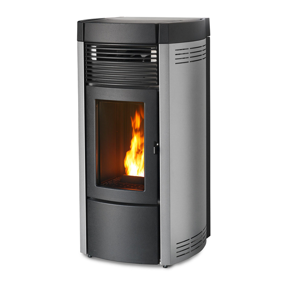
PELLET STOVE
CLIO HYDRO 16
CLIO HYDRO 23
CLIO
HYDRO 23 with exchanger
PART 1 - REGULATIONS AND ASSEMBLY
Instructions in English
Table of
Contents
Previous
Page
Next
Page
1
2
3
4
5
Advertisement
Table of Contents
Need help?
Do you have a question about the CLIO HYDRO 16 and is the answer not in the manual?
Ask a question
Questions and answers
Related Manuals for MCZ CLIO HYDRO 16
Stove MCZ Hydrotherm 80 Installation And Use Manual
(33 pages)
Stove MCZ Hydrotherm 70 Installation And Use Manual
(33 pages)
Stove MCZ CLIO HYDRO 23 Instructions Manual
(44 pages)
Stove MCZ HALO AIR 8 M2 Installation Manual
Sealed pellet stove (72 pages)
Stove MCZ HALO AIR 8 M2 Assembly Manual
Sealed pellet stove (44 pages)
Stove MCZ HERA AIR 7 S1 Installation Manual
Sealed pellet stove (76 pages)
Stove MCZ HALO AIR 8 M1 Installation Manual
(64 pages)
Stove MCZ HALO AIR 8 M1 Installation Manual
Sealed pellet stove (36 pages)
Stove MCZ CLIO HYDRO 16 S2 Installation Manual
(48 pages)
Stove MCZ CLIO HYDRO 23 S2 Installation Manual
(36 pages)
Stove MCZ THEA HYDRO 16 S1 Installation Manual
(36 pages)
Stove MCZ THEA HYDRO 16 S1 Installation Manual
(48 pages)
Stove MCZ VIVO 90 HYDRO 16 M1 Use And Installation Manual
Pellet insert (52 pages)
Stove MCZ THEA HYDRO 16 S2 Installation Manual
(36 pages)
Stove MCZ EGO AIR Use And Maintenance Manual
(54 pages)
Stove MCZ Polar Installation And Use Manual
(65 pages)
This manual is also suitable for:
Clio hydro 23
Clio hydro 23 with exchanger
Table of Contents
Print
Rename the bookmark
Delete bookmark?
Delete from my manuals?
Login
Sign In
OR
Sign in with Facebook
Sign in with Google
Upload manual
Upload from disk
Upload from URL


Need help?
Do you have a question about the CLIO HYDRO 16 and is the answer not in the manual?
Questions and answers