Nobu NBO-09IDU Installation Manual
Wall mounted air-conditioning unit
Hide thumbs
Also See for NBO-09IDU:
- Service manual (54 pages) ,
- User manual (15 pages) ,
- User manual (16 pages)
Table of Contents
Advertisement
Available languages
Available languages
Quick Links
Επιτοίχια Μονάδα Κλιματισμού
Wall Mounted Air-Conditioning Unit
ΜΟΝΤΕΛΑ/MODELS:
For correct use of this unit, please read this manual carefully and keep it for future reference.
NBO-09IDU/NBO-09ΟDU
NBO-12IDU/NBO-12ΟDU
NBO-18IDU/NBO-18ΟDU
NBO-24IDU/NBO-24ΟDU
Wall Mounted Air-Conditioning Unit
Installation Manual
Εγχειρίδιο Εγκατάσταση
Για τη σωστή χρήση τη
ονάδα , παρακαλού ε διαβάστε προσεκτικά το εγχειρίδιο
Επιτοίχια Μονάδα Κλι ατισ ού
και φυλάξτε το για αναφορά στο έλλον.
English/Ελληνικά
Advertisement
Chapters
Table of Contents

Related Manuals for Nobu NBO-09IDU


Summary of Contents for Nobu NBO-09IDU
- Page 1 Επιτοίχια Μονάδα Κλιματισμού Wall Mounted Air-Conditioning Unit ΜΟΝΤΕΛΑ/MODELS: NBO-09IDU/NBO-09ΟDU NBO-12IDU/NBO-12ΟDU NBO-18IDU/NBO-18ΟDU NBO-24IDU/NBO-24ΟDU Wall Mounted Air-Conditioning Unit Installation Manual Επιτοίχια Μονάδα Κλι ατισ ού Εγχειρίδιο Εγκατάσταση English/Ελληνικά Για τη σωστή χρήση τη ονάδα , παρακαλού ε διαβάστε προσεκτικά το εγχειρίδιο και φυλάξτε το για αναφορά στο έλλον.
-
Page 2: Table Of Contents
Table of Contents Installation Manual ........4 Safety Precautions Accessories ........... 6 ..Installation Summary - Indoor Unit ............ 10 Unit Parts ..11 Indoor Unit Installation 1. Select installation location ......11 2. Attach mounting plate to wall ....12 3. - Page 3 Refrigerant Piping Connection ..... 25 A. Note on Pipe Length ............B. Connection Instructions –Refrigerant Piping ... 1. Cut pipe ................2. Remove burrs ..............3. Flare pipe ends ............... 4. Connect pipes ..............Air Evacuation ....... 1. Evacuation Instructions ..... 2.
-
Page 4: Safety Precautions
Safety Precautions Read Safety Precautions Before Installation Incorrect installation due to ignoring instructions can cause serious damage or injury. The seriousness of potential damage or injuries is classified as either a WARNING or CAUTION. This symbol indicates that ignoring instructions may cause death or serious injury. - Page 5 WARNING 6. For all electrical work, follow all local and national wiring standards, regulations, and the Installation Manual. You must use an independent circuit and single outlet to supply power. Do not connect other appliances to the same outlet. Insufficient electrical capacity or defects in electrical work can cause electrical shock or fire.
-
Page 6: Accessories
Accessories The air conditioning system comes with the following accessories. Use all of the installation parts and accessories to install the air conditioner. Improper installation may result in water leakage, electrical shock and fire, or cause the equipment to fail. Name Shape Quantity... - Page 7 Name y t i Επιτοίχια Μονάδα Κλιματισμού Wall Mounted Air-Conditioning Unit ΜΟΝΤΕΛΑ/MODELS: NBO-09IDU/NBO-09ΟDU NBO-12IDU/NBO-12ΟDU NBO-18IDU/NBO-18ΟDU NBO-24IDU/NBO-24ΟDU Wall Mounted Air-Conditioning Unit User’s Manual Επιτοίχια Μονάδα Κλι ατισ ού Εγχειρίδιο Χρήση Owner’s manual English/Ελληνικά Για τη σωστή χρήση τη ονάδα , παρακαλού ε διαβάστε προσεκτικά το εγχειρίδιο...
-
Page 8: Installation Summary - Indoor Unit
Installation Summary - Indoor Unit 15cm (5.9in) or more 12cm (4.75in) 12cm (4.75in) or more or more 2.3m (90.55in) or more Select Installation Location Determine Wall Hole Position (Page 11) (Page 12) Attach Mounting Plate Drill Wall Hole (Page 12) (Page 12) ... - Page 9 Connect Piping Connect Wiring Prepare Drain Hose (Page 25) (Page 17) (Page 14) Wrap Piping and Cable (Page 18) STEP Mount Indoor Unit (Page 18) Page 9...
-
Page 10: Unit Parts
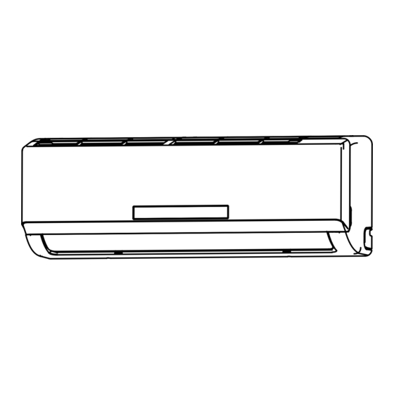
Unit Parts Wall Mounting Plate Front Panel Power Cable (Some Units) Louver Drainage Pipe Functional Filter (On Front of Main Filter - Some Units) Signal Cable Refrigerant Piping Remote Control (Some Units) Remote Holder Outdoor Unit Power Cable (Some Units) Fig. -
Page 11: Indoor Unit Installation
Indoor Unit Installation DO NOT install unit in the following Installation Instructions – Indoor locations: Unit Near any source of heat, steam, or combustible gas PRIOR TO INSTALLATION Near flammable items such as curtains or Before installing the indoor unit, refer to the clothing label on the product box to make sure that the model number of the indoor unit matches the... -
Page 12: Attach Mounting Plate To Wall
Refer to the following diagram to ensure proper distance from walls and ceiling: 15cm (5.9in) or more 12cm (4.75in) 12cm (4.75in) or more or more Fig. 3.1 2.3m (90.55in) or more Step 2: Attach mounting plate to wall Step 3: Drill wall hole for connective piping The mounting plate is the device on which you You must drill a hole in the wall for refrigerant will mount the indoor unit. - Page 13 715mm(28in) W all 387mm(15.2in) Indoor Outdoor Indoor unit outline 85mm(3.3in) 88mm(3.5in) Left rear wall Right rear wall hole 65mm (2.5in) hole 65mm (2.5in) MODEL A 800mm(31.5in) 420mm(16.5in) Fig. 3.2 100mm(3.9in) 95mm(3.7in) MOUNTING PLATE DIMENSIONS Left rear wall Different models have different mounting plates. Right rear wall hole 65mm (2.5in) hole 65mm (2.5in)
-
Page 14: Prepare Refrigerant Piping
Step 4: Prepare refrigerant piping 3. Use scissors to cut down the length of the insulating sleeve to reveal about 15cm (6in) The refrigerant piping is inside an insulating of the refrigerant piping. This serves two sleeve attached to the back of the unit. You must purposes: prepare the piping before passing it through the hole in the wall. -
Page 15: Connect Drain Hose
Step 5: Connect drain hose PLUG THE UNUSED DRAIN HOLE By default, the drain hose is attached to the left- To prevent unwanted leaks you must plug hand side of unit (when you’re facing the back the unused drain hole with the rubber plug of the unit). - Page 16 BEFORE PERFORMING ELECTRICAL WORK, READ THESE REGULATIONS 1. All wiring must comply with local and national electrical codes, and must be installed by a licensed electrician. 2. All electrical connections must be made according to the Electrical Connection Diagram located on the panels of the indoor and outdoor units. 3.
-
Page 17: Connect Signal Cable
Step 6: Connect signal cable TAKE NOTE OF FUSE SPECIFICATIONS The signal cable enables communication between The air conditioner’ s circuit board (PCB) is the indoor and outdoor units. You must first designed with a fuse to provide overcurrent choose the right cable size before preparing it for protection. -
Page 18: Wrap Piping And Cables
6. Feed the signal wire through this slot, from DO NOT INTERTWINE SIGNAL CABLE WITH the back of the unit to the front. OTHER WIRES 7. Facing the front of the unit, match the wire While bundling these items together, do not colors with the labels on the terminal block, intertwine or cross the signal cable with any connect the u-lug and and firmly screw each... - Page 19 3. Connect drain hose and refrigerant piping If refrigerant piping is already embedded in the wall, do the following: (refer to Refrigerant Piping Connection section of this manual for instructions). 1. Hook the top of the indoor unit on the upper 4.
-
Page 20: Outdoor Unit Installation
Outdoor Unit Installation Installation Instructions – Outdoor Unit Step 1: Select installation location Before installing the outdoor unit, you must choose an appropriate location. The following are standards that will help you choose an appropriate location for the unit. Proper installation locations meet the following standards: ... -
Page 21: Install Drain Joint
If the drain joint comes with a rubber seal SPECIAL CONSIDERATIONS FOR EXTREME (see Fig. 4.4 - A ), do the following: WEATHER 1. Fit the rubber seal on the end of the drain joint If the unit is exposed to heavy wind: that will connect to the outdoor unit. -
Page 22: Anchor Outdoor Unit
Step 3: Anchor outdoor unit The outdoor unit can be anchored to the ground or to a wall-mounted bracket. UNIT MOUNTING DIMENSIONS Air inlet The following is a list of different outdoor unit sizes and the distance Air inlet between their mounting feet. Prepare the installation base of the unit according to the dimensions Air outlet... -
Page 23: Connect Signal And Power Cables
If you will install the unit on a wall-mounted BEFORE PERFORMING bracket , do the following: ELECTRICAL WORK, READ THESE REGULATIONS 1. All wiring must comply with local and CAUTION national electrical codes, and must be Before installing a wall-mounted unit, make installed by a licensed electrician. - Page 24 PAY ATTENTION TO LIVE WIRE WARNING While crimping wires, make sure you clearly BEFORE PERFORMING ANY ELECTRICAL distinguish the Live (“L”) Wire from other wires. OR WIRING WORK, TURN OFF THE MAIN POWER TO THE SYSTEM. WARNING 1. Prepare the cable for connection: ALL WIRING MUST PERFORMED STRICTLY USE THE RIGHT CABLE IN ACCORDANCE WITH THE WIRING...
-
Page 25: Refrigerant Piping Connection
Refrigerant Piping Connection Note on Pipe Length The length of refrigerant piping will affect the performance and energy efficiency of the unit. Nominal efficiency is tested on units with a pipe length of 5 meters (16.5ft). Refer to the table below for specifications on the maximum length and drop height of piping. Maximum Length and Drop Height of Refrigerant Piping per Unit Model Model Capacity (BTU/h) -
Page 26: Remove Burrs
DO NOT DEFORM PIPE Flare nut WHILE CUTTING Be extra careful not to damage, dent, or deform the pipe while cutting. This will drastically reduce the heating efficiency of the unit. Copper pipe Step 2: Remove burrs Burrs can affect the air-tight seal of refrigerant piping connection. -
Page 27: Connect Pipes
6. Place flaring tool onto the form. Instructions for Connecting Piping to 7. Turn the handle of the flaring tool clockwise Indoor Unit until the pipe is fully flared. 1. Align the center of the two pipes that you will 8. - Page 28 Instructions for Connecting Piping to USE SPANNER TO GRIP MAIN Outdoor Unit BODY OF VALVE Torque from tightening the flare nut can snap 1. Unscrew the cover from the packed valve on off other parts of valve. the side of the outdoor unit. (See Fig. 5.9 ) Valve cover Fig.
-
Page 29: Air Evacuation
Air Evacuation Preparations and Precautions Evacuation Instructions Air and foreign matter in the refrigerant circuit Before using the manifold gauge and vacuum can cause abnormal rises in pressure, which pump, read their operation manuals to familiarize can damage the air conditioner, reduce its yourself with how to use them properly. -
Page 30: Note On Adding Refrigerant
Open the Low Pressure side of the manifold gauge. Keep the High Pressure side closed. Flare nut Turn on the vacuum pump to evacuate the system. Run the vacuum for at least 15 minutes, or until the Compound Meter reads -76cmHG (-10 Pa). -
Page 31: Electrical And Gas Leak Checks
Electrical and Gas Leak Checks Electrical Safety Checks WARNING – RISK OF ELECTRIC SHOCK After installation, confirm that all electrical wiring ALL WIRING MUST COMPLY WITH LOCAL is installed in accordance with local and national AND NATIONAL ELECTRICAL CODES, regulations, and according to the Installation AND MUST BE INSTALLED BY A LICENSED Manual. -
Page 32: Test Run
Test Run PASS/FAIL Before Test Run List of Checks to Perform No electrical leakage Only perform test run after you have completed the following steps: Unit is properly grounded • Electrical Safety Checks – Confirm that the unit’ s electrical system is safe and All electrical terminals operating properly properly covered... - Page 33 DOUBLE-CHECK PIPE CONNECTIONS During operation, the pressure of the refrigerant circuit will increase. This may reveal leaks that were not present during your initial leak check. Take time during the Test Run to double-check that all refrigerant pipe connection points do not have leaks. Refer to Gas Leak Check section for instructions.
-
Page 34: European Disposal Guidelines
European Disposal Guidelines This appliance contains refrigerant and other potentially hazardous materials. When disposing of this appliance, the law requires special collection and treatment. Do not dispose of this product as household waste or unsorted municipal waste. When disposing of this appliance, you have the following options: •... - Page 35 Πίνακας Περιεχομένων Εγχειρίδιο Εγκατάσταση Οδηγίε Ασφαλεία ........4 Εξαρτή ατα ..........6 Περίληψη Εγκατάσταση - Εσωτερική Μονάδα ..Μέρη Μονάδα ........... 10 Εγκατάσταση Εσωτερική Μονάδα 11 1. Επιλέξτε τοποθεσία εγκατάσταση ..11 2. Προσαρ όστε την επιτοίχια βάση ....12 3. Ανοίξτε τρύπα στον τοίχο για τη σύνδεση του αγωγού 12 4.
- Page 36 Σύνδεση Αγωγού Ψυκτικού Μέσου ..25 Α. Ση είωση σχετικά ε το ήκο αγωγού ......25 B. Οδηγίε Σύνδεση - Αγωγό Ψυκτικού Μέσου ....25 1. Κόψτε τον Αγωγό ..............25 2. Αφαιρέστε τα γρέζια .............. 26 3. Ενώστε τι άκρε των αγωγών ........... 26 4.
-
Page 37: Οδηγίε Ασφαλεία
Οδηγίε Ασφαλεία ιαβάστε τι Οδηγίε Ασφαλεία πριν την εγκατάσταση Εσφαλ ένη εγκατάσταση λόγω αγνόηση των οδηγιών πορεί να προκαλέσει σοβαρέ καταστροφέ ή τραυ ατισ ού . Η σοβαρότητα των πιθανών καταστροφών ή τραυ ατισ ών ε φανίζεται ω ΠΡΟΕΙ ΟΠΟΙΗΣΗ ή ΠΡΟΣΟΧΗ. Αυτό... - Page 38 ΠΡΟΕΙ ΟΠΟΙΗΣΗ 6. Για ηλεκτρολογικέ διεργασίε , ακολουθήστε τι τοπικέ και εθνικέ ηλεκτρολογικέ προδιαγραφέ , νό ου και εγχειρίδια εγκατάσταση . Θα πρέπει να χρησι ποιείτε ανεξάρτητο κύκλω α τροφοδοσία ε ρεύ α και ξεχωριστή πρίζα. Μην συνδέετε άλλε συσκευέ στην ίδια πρίζα. Αναποτελεσ ατική παροχή...
-
Page 39: Εξαρτή Ατα
Εξαρτή ατα Η κλι ατιστική ονάδα παρέχεται ε τα ακόλουθα εξαρτή ατα. Χρησι οποιήστε όλα τα έρη εγκατάσταση και τα εξαρτή ατα ώστε να εγκαταστήσετε το κλι ατιστικό. Εσφαλ ένη εγκατάσταση πορεί να έχει ω αποτέλεσ α διαροοή νερού, ηλεκτροπληξία και φωτιά, ή καταστροφέ στο προϊόν. Όνο... - Page 40 Όνο α Σχή α Ποσότητα Επιτοίχια Μονάδα Κλιματισμού Wall Mounted Air-Conditioning Unit ΜΟΝΤΕΛΑ/MODELS: NBO-09IDU/NBO-09ΟDU NBO-12IDU/NBO-12ΟDU NBO-18IDU/NBO-18ΟDU NBO-24IDU/NBO-24ΟDU Wall Mounted Air-Conditioning Unit User’s Manual Επιτοίχια Μονάδα Κλι ατισ ού Εγχειρίδιο Χρήση Εγχειρίδιο Χρήστη English/Ελληνικά Για τη σωστή χρήση τη ονάδα , παρακαλού ε διαβάστε προσεκτικά το εγχειρίδιο...
-
Page 41: Τυλίξτε Καλώδια Και Αγωγού
Περίληψη Εγκατάστασης - Εσωτερική Μονάδα 15cm (5.9in) ή περισσότερο 12cm 12cm (4.75in) (4.75in) ή περισσότερο ή περισσότερο 2.3m (90.55in) ή περισσότερο Επιλέξτε θέση Εγκατάσταση Επιλέξτε τη θέση ανοίγ ατο οπή στον τοίχο (Σελίδα 11) (Σελίδα 12) Προσαρ όστε την επιτοίχια πλακέτα Ανοίξτε... - Page 42 Προετοι άστε τον αγωγό αποστράγγιση Συνδέστε του αγωγού Συνδέστε τι καλωδιώσει (Σελίδα 25) (Σελίδα 17) (Σελίδα 14) Τυλίξτε Αγωγού και Καλωδιώσει (Σελίδα 18) STEP Τοποθετήστε την Εσωτερική Μονάδα (Σελίδα 18) Σελίδα 9 ƒ „...
-
Page 43: Μέρη Μονάδα
Μέρη Μονάδα Βάση στήριξη Καλώδιο Ρεύ ατο (Ορισ ένε Μονάδε ) Μπροστινό Πάνελ Περσίδα Αγωγό Αποστράγγιση Λειτουργικό Φίλτρο (Μπροστά στο Κύριο Φίλτρο-Ορισ ένε Μονάδε ) Καλώδιο Σή ατο Αγωγό ψυκτικού έσου Τηλεχειριστήριο (Ορισ ένε Μονάδε ) Βάση Τηλεχειριστηρίου Εξωτερική Μονάδα Καλώδιο... -
Page 44: Εγκατάσταση Εσωτερική Μονάδα
Εγκατάσταση Εσωτερική Μονάδα ΜΗΝ εγκαθιστάτε τη ονάδα στι ακόλουθε Οδηγίε Εγκατάσταση - Εσωτερική τοποθεσίε : Μονάδα Δίπλα σε πηγές θερμότητας ή εύφλεκτων αερίων ΣΗΜΑΝΤΙΚΟ ΣΤΗΝ ΕΓΚΑΤΑΣΤΑΣΗ Δίπλα σε εύφλεκτα αντικείμενα όπως κουρτίνες Πριν την εγκατάσταση της εσωτερικής μονάδας, ανατρέξτε ή ρούχα στο... -
Page 45: Προσαρ Όστε Την Επιτοίχια Βάση
Ανατρέξτε στο ακόλουθο διάγρα α ώστε να επιβεβαιώσετε την κατάλληλη απόσταση από του τοίχου και την οροφή: 15cm (5.9in) ή περισσότερο 12cm (4.75in) 12cm (4.75in) ή περισσότερο ή περισσότερο 2.3m (90.55in) ή περισσότερο Σχ. 3.1 Βήμα 2: Προσαρμόστε την επιτοίχια πλακέτα στον τοίχο Βήμα... - Page 46 717mm(28.2in) Τοίχο 412mm(16.2in) 128mm(5.0in) 237mm(9.3in) Εσωτερικό Εξωτερικό Indoor unit outline Left rear wall Right rear wall hole 65mm (2.5in) hole 65mm (2.5in) 137mm(5.4in) 117mm(4.6in) 107mm(4.2in) 39mm (1.5in) Μοντέλο A 805mm(31.7in) 427.9mm(16.8in) 163mm(6.5in) 224.6mm(8.8in) Indoor unit outline Fig.3.2 Εικ. 3.2 Left rear wall Right rear wall hole 65mm (2.5in) hole 65mm (2.5in)
-
Page 47: Προετοι Άστε Τη Σωλήνα Του Ψυκτικού Έσου
Βή α 4: Προετοι άστε τον αγωγό ψυκτικού έσου 3. Χρησι οποιήστε ψαλίδια να κόψετε το ήκο Ο αγωγό ψυκτικού έσου είναι εντό τη προστα- τη ονωτική ταινία αφήνοντα περίπου 15cm τευ ένη θήκη στο πίσω έρο τη ονάδα . Πρέπει (6in) από... -
Page 48: Ενώστε Τον Αγωγό Αποστράγγιση
Βή α 5. Συνδέστε τον αγωγό αποστράγγιση ΦΡΑΞΤΕ ΤΟΝ ΑΧΡΗΣΙΜΟΠΟΙΗΤΟ ΑΓ ΓΟ ΑΠΟΣΤΡΑΓΓΙΣΗΣ Προεπιλεγ ένα, ο αγωγό αποστράγγιση Για να αποφύγετε ανεπιθύ ητε διαρροέ θα είναι ενσω ατω ένο στην αριστερή πλευρά πρέπει να φράσετε τον αχρησι οποίητο αγωγό τη ονάδα... - Page 49 ΠΡΙΝ ΕΚΚΙΝΗΣΕΤΕ ΤΙΣ ΗΛΕΚΤΡΟΛΟΓΙΚΕΣ ΕΡΓΑΣΙΕΣ, ΙΑΒΑΣΤΕ ΑΥΤΕΣ ΤΙΣ Ο ΗΓΙΕΣ 1. Η ηλεκτρολογικέ συνδέσει θα πρέπει να συ φωνούν πλήρω ε τι τοπικέ και εθνικέ οδηγίε και θα πρέπει να εγκατασταθούν από εξουσιοδοτη ένο ηλεκτρολόγο. 2. Όλε οι ηλεκτρολογικέ συνδέσει πρέπεινα είναι σύ φωνε ε...
-
Page 50: Ενώστε Το Καλώδιο Σή Ατο
ΣΗΜΕΙ ΣΤΕ ΤΙΣ ΠΡΟ ΙΑΓΡΑΦΕΣ ΚΑΛ ΙΟΥ ΑΣΦΑΛΕΙΑΣ Βή α 6: Συνδέστε το καλώδιο σή ατο Ο ηλεκτρολογικό πίνακα του κλι ατιστικού είναι Το καλώδιο σή ατο διευκολύνει την επικοινωνία σχεδιασ ένο ε καλώδιο ασφαλεία ώστε να παρέχει εταξύ εξωτερική και εσωτερική ονάδα... -
Page 51: Συνδέστε Το Εσωτερικό Καλώδιο Ρεύ Ατο
6. Τροφοδοτήστε το καλώδιο σή ατο έσω ΜΗΝ ΜΠΛΕΚΕΤΕ ΤΑ ΚΑΛ ΙΑ ΣΗΜΑΤΟΣ ΜΕ ΤΑ αυτή τη υποδοχή , από το πίσω έρο τη ΥΠΟΛΟΙΠΑ ΚΑΛ ΙΑ ονάδα στο προστινό. Όταν τυλιγέτε τα καλώδια αζί, ην πλέκετε ή 7. Βλέποντα το προστινό έρο τη ονάδα... - Page 52 3. Συνδέστε τον σύνδεσ ο αποστράγγιση και Αν ο αγωγό ψυκτικού έσου είναι έτοι ο να τον αγωγό ψυκτικού έσου (ανατρέξτε στην διαπεράσει τον τοίχο, ακολουθήστε το παρακάτω: ενότητα Αγωγό Ψυκτικού Μέσου αυτού του 1. Κρε άστε την εσωτερική ονάδα στη επιτοίχια εγχειριδίου...
- Page 53 Εγκατάσταση Εξωτερική Μονάδα Οδηγίε Εγκατάσταση - Εξωτερική Μονάδα Βή α 1. Επιλέξτε τοποθεσία εγκατάσταση Πριν εγκαταστήσετε την εξωτερική ονάδα, πρέπει να επιλέξετε τη κατάλληλη θέση. Οι ακόλουθε προδιαγραφέ θα σα βοηθήσουν να επιλέξετε ια κατάλληλη τοποθεσία για τη ονάδα. Οι κατάλληλε τοποθεσίε εγκατάσταση συναντούν τι...
- Page 54 Εάν ο σύνδεσ ο φέρει λαστιχένια τσι ούχα ΕΙ ΙΚΕΣ ΣΥΝΘΗΚΕΣ ΓΙΑ ΕΝΤΟΝΑ ( είτε Σχ. 4.4-Α), κάντε τα ακόλουθα: ΚΑΙΡΙΚΑ ΦΑΙΝΟΜΕΝΑ 1. Προσαρ όστε τη λαστιχένια τσι ούχα στο τέλο του Αν η ονάδα εκτίθεται σε έντονο άνε ο: συνδέσ...
- Page 55 Βή α 3: Στερεώστε την εξωτερική ονάδα Η εξωτερική ονάδα πορεί να στερεωθεί στο έδαφο ή σε επιτοίχιο βραχίονα. ΙΑΣΤΑΣΕΙΣ ΕΞ ΤΕΡΙΚΗΣ ΜΟΝΑ ΑΣ Είσοδος Αέρα Τα ακόλουθα είναι ια λίστα από Είσοδος διαφορετικέ διαστάσει εξωτερικών Αέρα ονάδων και αποστάσει εταξύ...
- Page 56 Αν εγκαταστήσετε την ονάδα σε επιτοίχιο ΠΡΙΝ ΠΡΑΓΜΑΤΟΠΟΙΗΣΕΤΕ βραχίονα, κάντε τα ακόλουθα: ΗΛΕΚΤΡΟΛΟΓΙΚΕΣ ΙΕΡΓΑΣΙΕΣ, ΙΑΒΑΣΤΕ ΤΙΣ Ο ΗΓΙΕΣ ΠΡΟΣΟΧΗ 1. Όλε οι καλωδιώσει θα πρέπει να είναι σύ φωνε ε του τοπικού και εθνικού ηλεκτρολογικού κανονισ ού και θα πρέπει να εγκαθιστώνται από Πριν...
- Page 57 ΠΡΟΣΕΞΤΕ ΤΟ ΚΑΛ ΙΟ ΦΑΣΗΣ ΠΡΟΕΙ ΟΠΟΙΗΣΗ Όταν πιέζετε τα καλώδια, βεβαιωθείτε ότι έχετε ΠΡΙΝ ΞΕΚΙΝΗΣΕΤΕ ΟΠΟΙΑ ΗΠΟΤΕ ΗΛΕΚΤΡΟΝΙΚΗ ξεκαθαρίσει το καλώδιο φάση από τα υπόλοιπα ΚΑΙ ΗΛΕΚΤΡΟΛΟΓΙΚΗ ΙΕΡΓΑΣΙΑ, ΑΠΕΝΕΡΓΟΠΟΙΗΣΤΕ καλώδια. ΤΗ ΚΥΡΙΑ ΤΡΟΦΟ ΟΣΙΑ ΤΟΥ ΣΥΣΤΗΜΑΤΟΣ. ΠΡΟΕΙ ΟΠΟΙΗΣΗ 1. Προετοι άστε το καλώδιο για σύνδεση: ΟΛΕΣ...
- Page 58 ΣΥΝ ΕΣΗ ΑΓ ΓΟΥ ΨΥΚΤΙΚΟΥ ΜΕΣΟΥ Ση είωση στο Μήκο του Αγωγού Το ήκο του αγωγού ψυκτικού έσου θα επηρεάσει την λειτουργία και την ενεργειακή απόδοση τη ονάδα . Η εικονική απόδοση είναι ελεγ ένη στι ονάδε ε ήκο αγωγού 5 έτρων (16.5ft). Ανατρέξτε...
- Page 59 ΜΗΝ ΠΑΡΑΜΟΡΦ ΝΕΤΕ ΤΟΝ Παξι άδι Εκχείλωση ΑΓ ΓΟ ΚΑΤΑ ΤΗ ΚΟΠΗ Να είστε ιδιαίτερα προσεκτικοί να ην καταστρέψετε, λυγίσετε ή παρα ορφώσετε τον αγωγό κατά τη διάρκεια κοπή . Αυτό πορεί δραστικά να ειώσει την απόδοση θέρ ανση τη ονάδα...
- Page 60 6. Τοποθετήστε το εργαλείο εκχείλωση έσα Οδηγίε για Σύνδεση του Αγωγού στην στη φόρ α. Εσωτερική Μονάδα 7. Γυρίστε το εργαλείο εκχείλωση ε φορά ρολογιού, έχρι να πραγ ατοποιηθεί η εκχείλωση. 1. Ευθυγρα ίστε στο κέντρο του δυο αγωγού 8. Αφαιρέστε το εργαλείο εκχείλωση και τη φόρ α αυτού, ετά...
- Page 61 Οδηγίε Σύνδεση Αγωγού στην ΧΡΗΣΙΜΟΠΟΙΗΣΤΕ ΓΕΡΜΑΝΙΚΟΚΛΕΙ Ι Εξωτερική Μονάδα ΓΙΑ ΝΑ ΚΡΑΤΗΣΕΤΕ ΤΟ Σ ΜΑ ΤΗΣ ΒΑΛΒΙ ΑΣ Η ροπή από την εκχείλωση πορεί να προκαλέσει 1. Ξεβιδώστε το κάλυ α από τη πλακέτα τη φθορά ή να κόψει τ ή α τη βαλβίδα . εξωτερική...
- Page 62 Εξαέρωση Προεργασία και Οδηγίε Οδηγίε Εξαέρωση Αέρα και άλλα ξένα στοιχεία στο ψυκτικό κύκλο Πριν χρησι οποιήσετε τη βαλβίδα πολλαπλή και πορεί να προκαλέσουν ασυνήθιστη αύξηση στη την αντλία κενού, διαβάστε τα εγχειρίδια λειτουργία . πίεση, το οποίο πορεί να καταστρέψει το κλι α- τιστικό, να...
- Page 63 3. Ανοίξτε τη πλευρά Χα ηλή Πίεση τη πολλαπλή βαλβίδα . Κρατήστε τη πλευρά Υψηλή Πίεση κλειστή. 4. Ενεργοποιήστε την αντλία κενού ώστε να εξαερώσετε Παξι άδι Εκχείλωση το σύστη α. 5. Ενεργοποιήστε την αντλία κενού για τουλάχιστον 15 λεπτά ή έω ότου η ένωση των ετρήσεων δείξει -76cmHG (-10 Pa).
- Page 64 Έλεγχο Ηλεκτρολογική ιαρροή και ιαρροή Αερίου ΠΡΟΕΙ ΟΠΟΙΗΣΗ- ΚΙΝ ΥΝΟΣ Έλεγχο Ηλεκτρολογική Ασφάλεια ΓΙΑ ΗΛΕΚΤΡΟΠΛΗΞΙΑ Μετά την εγκατάσταση, επιβεβαιώστε ότι όλε οι ΟΛΕΣ ΟΙ ΚΑΛ Ι ΣΕΙΣ ΠΡΕΠΕΙ ΝΑ ΕΙΝΑΙ ΣΕ ηλεκτρολογικέ καλωδιώσει είναι σε πλήρη συ - ΠΛΗΡΗ ΣΥΜΦ ΝΙΑ ΜΕ ΤΟΥΣ ΤΟΠΙΚΟΥΣ ΚΑΙ φωνία...
- Page 65 ΟΚΙΜΑΣΤΙΚΗ ΛΕΙΤΟΥΡΓΙΑ Πριν τη οκι αστική Λειτουργία ΠΕΡΑΣΕ / ΑΠΕΤΥΧΕ Λίστα Πραγ ατοποίηση Ελέγχων εν υπάρχει ηλεκτρολογική διαρροή Πραγ ατοποιήστε δοκι αστικό έλεγχο όνο Η ονάδα είναι σταθερά αφότου έχετε ολοκληρώσει τα ακόλουθα βή ατα: εδραιω ένη • Έλεγχος Ασφαλείας Ηλεκτρικών: Επιβεβαιώστε ότι το...
- Page 66 ΙΠΛΟΣ ΕΛΕΓΧΟΣ ΣΥΝ ΕΣΗΣ ΑΓ ΓΟΥ Κατά τη λειτουργία, η πίεση του ψυκτικού κύκλου θα αυξηθεί. Αυτό πορεί να προκαλέσει διαρροή ρευστού που δεν υπήρχε στον αρχικό έλεγχο διαρροών. Πάρτε χρόνο να ελέγξετε διπλά πω όλα τα ση εία του αγωγού...
- Page 67 Ευρωπαϊκέ Προδιαγραφέ Απόρριψη Αυτή η συσκευή περιέχει ψυκτκό υγρό και άλλα πιθανώ επικίνδυνα υλικά. Όταν θέλετε να απορρίψετε αυτή τη συσκευή, ο νόμος προϋποθέτει ειδική περισυλλογή και μεταχείριση. ΜΗΝ απορρίπτετε αυτό το προϊόν όπω τα οικιακά ή δη οτικά απορρί ατα. Όταν...
- Page 68 Επιτοίχια Μονάδα Κλιματισμού Wall Mounted Air-Conditioning Unit...
Need help?
Do you have a question about the NBO-09IDU and is the answer not in the manual?
Questions and answers