
Related Manuals for Kobelt 6300-0100


Summary of Contents for Kobelt 6300-0100
- Page 1 Kobelt Steering System 6300-0100 Controller & 6300-0200 Station Owner’s Operation, Installation & Maintenance Manual May 2023 (rev A)
- Page 2 Kobelt Steering System Kobelt Manufacturing Co. Ltd. NOTES RECORD DATA BEFORE INSTALLATION FOR FUTURE REFERENCE Model #: Serial #: Date of Purchase: Date of Installation: rev A MNL-002.docx 2 of 126...
-
Page 3: Table Of Contents
Notice to Installer ......................9 Product Hazards....................... 10 Scope ..........................11 Terminology and Definitions ..................12 Stations ..........................12 Kobelt Steering System overview .................. 13 System Description ......................13 System Features ......................16 Controller ......................... 17 Steering Station ....................... 17 Technical Specifications .................... - Page 4 Kobelt Steering System Kobelt Manufacturing Co. Ltd. Calibration and Adjustment .................... 74 Functional Test ........................ 82 Operation ........................86 Station Transfer Mode ..................... 86 Station Control ......................... 87 Steering Control ....................... 91 Steering Modes ........................ 91 Local Emergency Backup Control ..................94 Autopilot Control ......................
- Page 5 Kobelt Steering System Kobelt Manufacturing Co. Ltd. IGURES Figure 1: Single Rudder Steering System Block Diagram (Simplified) ................14 Figure 2:Dual Rudder Steering System Block Diagram (Simplified) ................15 Figure 3: Steering System Block Diagram Render ......................16 Figure 4: KNET Ferrite Choke ............................21 Figure 5: Wheel Connector EMC Clamp Diagram ......................
- Page 6 Kobelt Steering System Kobelt Manufacturing Co. Ltd. Figure 47: Restore Configuration Confirmation Screen ....................54 Figure 48: Save Configuration Confirmation Screen ....................55 Figure 49: Success or Failed Screen ..........................55 Figure 50: Set Date/Time Screen ..........................56 Figure 51: Set Valve Type Screen ..........................56 Figure 52: Set FRU Type Screen ...........................
- Page 7 Kobelt Steering System Kobelt Manufacturing Co. Ltd. IST OF ABLES Table 1: Technical Specifications Controller and Head ....................18 Table 2: KNet Cable Properties ............................ 22 Table 3: KNet Network Properties ..........................22 Table 4 Controller Overview Table ..........................23 Table 5: Valve Power Connector ..........................
-
Page 8: Introduction
Kobelt recommends that customers visit our website to check for updates to this Manual. Once a product has been selected for use, it should be tested by the user to ensure proper function in all possible applications. For further instructions, please contact our distributors or visit our website. -
Page 9: Safety
• Never put the product into service before fully completing installation and commissioning. • Do not carry out any modifications to the product. • Only use authentic Kobelt spare parts. • Observe all local regulations, directives, and laws during the installation of this product. -
Page 10: Product Hazards
2.3 P RODUCT AZARDS Equipment Starts Automatically: The Kobelt Steering Controller valve outputs are controlled remotely and/or through a control loop. They may be driven unintentionally through improper closed loop feedback and or unintentional operator commands. Ensure all power sources are disconnected or locked out prior to performing system maintenance or repair. -
Page 11: Scope
Information of any Autopilot interfacing to the Kobelt Steering System is not covered within this manual. The Kobelt Steering System is designed to connect to a correctly installed and commissioned hydro-mechanical steering gear. -
Page 12: Terminology And Definitions
Kobelt Manufacturing Co. Ltd. ERMINOLOGY AND EFINITIONS Before proceeding with the configuration and operation of the Kobelt Steering System, is it important for the user to become familiar with the terminology and basic functions used throughout this manual. 4.1 S TATIONS Stations are physical locations around the vessel where controls are located. -
Page 13: Kobelt Steering System Overview
Controller and one to four steering stations. The system is interconnected by the KNet network for communications and power. The Kobelt Steering System controls one or two hydraulic solenoid steering outputs for a single rudder, or two independent rudders. The valve outputs may be configured as on-off, or proportional control. -
Page 14: Figure 1: Single Rudder Steering System Block Diagram (Simplified)
Kobelt Steering System Kobelt Manufacturing Co. Ltd. Figure 1: Single Rudder Steering System Block Diagram (Simplified) rev A MNL-002.docx 14 of 126... -
Page 15: Figure 2:Dual Rudder Steering System Block Diagram (Simplified)
Kobelt Steering System Kobelt Manufacturing Co. Ltd. Figure 2:Dual Rudder Steering System Block Diagram (Simplified) rev A MNL-002.docx 15 of 126... -
Page 16: System Features
• One (1) Steering Controller unit. Graphical display for system commissioning, configuration, and diagnostics Built-in on-off/Proportional Electro-Hydraulic solenoid driver Integrates with legacy Kobelt RFU devices. Integrates with 3 -party autopilot systems. • Up to four (4) Steering Stations, each with a control panel and one or more input devices. -
Page 17: Controller
Kobelt Steering System Kobelt Manufacturing Co. Ltd. ▪ Automatic transfer allows a jog or wheel command to transfer to a given station. ▪ Optionally, use the station lock feature to prevent other stations from taking control. Includes an LED-strip-style rudder angle indicator and rudder order indicator on the front panel. -
Page 18: Technical Specifications
Kobelt Steering System Kobelt Manufacturing Co. Ltd. 5.5 T ECHNICAL PECIFICATIONS Table 1: Technical Specifications Controller and Head ELECTRICAL Controller (6300-0100) Steering Station (6300-0200) OPERATING VOLTAGE 12-24Vdc 12-24Vdc 0.35A max (without SBW OPERATING CURRENT at 24Vdc Max 0.2A wheel)1.35A (max with SBW wheel) -
Page 19: Installation
Kobelt Steering System Kobelt Manufacturing Co. Ltd. NSTALLATION 6.1 L OCATION EQUIREMENTS The location of the controller unit should be within 10m(32.7 ft) to the solenoid valves to reduce voltage drop. If a voltage RFU is used, the location of the controller should be within 18m(58.87ft) of the RFU to reduce electrical noise induced on the signal wires. -
Page 20: Compass Safe Distance
6.5.2 Shielded cable and grounding methods Shielded cables shall be utilized when connecting to the Kobelt Steering Controller and steering head. The shield of the cables shall be grounded at the controller.to ensure proper EMC compliance, the connected to the bonding of the ship. -
Page 21: Electrical Considerations For Installation
LECTRICAL CONSIDERATIONS FOR INSTALLATION 6.6.1 Cable Routing In areas of extreme EMC interference care should be taken in arranging the cabling of the Kobelt Steering system to maintain proper system performance. To achieve adequate system performance from the rudder feedback readings, the cable lengths should be kept to a minimum. -
Page 22: Table 2: Knet Cable Properties
Kobelt Steering System Kobelt Manufacturing Co. Ltd. 6.6.2 KNET Cabling requirements 6.6.2.1 Wire specification Table 2: KNet Cable Properties Light Cable (Micro/Drop) Mid(Backbone) Heavy Cable (Mini) Signal Wire Gauge 24 AWG 20 AWG 18 AWG Power Wire Gauge 22 AWG... -
Page 23: Controller Field Wiring Connections
Kobelt Steering System Kobelt Manufacturing Co. Ltd. If the main power source is 24Vdc, and with sufficient voltage drop in the network it is possible for the steering station to drop below its operating voltage and experience a station brown out. -
Page 24: Figure 7: The Controller Wiring
Kobelt Steering System Kobelt Manufacturing Co. Ltd. Utility Outputs Output Additional output ports for future functionality Utility Input Input Additional input ports for future functionality SD Card Input/Output SD Card for steering system logs Status Indicators Output Indicators for system status information... -
Page 25: Figure 9: Electrical Connector For Valve #1 (Channels A/B)
Kobelt Steering System Kobelt Manufacturing Co. Ltd. • Power supply input for all four coil drivers (Valve #1 and #2) • Power can come from any supply suitable for driving the solenoid valves. Valve power is isolated from KNet power supply, and they do not need to share a ground Valve supply voltage may be different than the KNet supply voltage, to a maximum of 24Vd.c. -
Page 26: Figure 10: Electrical Connector For Valve #2 (Channels C/D)
Kobelt Steering System Kobelt Manufacturing Co. Ltd. Figure 10: Electrical Connector for Valve #2 (Channels C/D) Table 7: Valve #2 Connector Membrane Pin # Pin Designator Pin Type Function Symbol Coil C+ Output Valve #2, CHC, Positive Output Coil C-... -
Page 27: Figure 11: Valve Wiring For Solenoid Valves (4-Wire)
Kobelt Steering System Kobelt Manufacturing Co. Ltd. Figure 11: Valve Wiring for Solenoid Valves (4-Wire) Figure 12: Valve Wiring for Solenoid Valves (Common Negative) Figure 13: Valve Wiring for Solenoid Valves (Common Positive) rev A MNL-002.docx 27 of 126... - Page 28 • Collectively, these are referred to as Channels A, B, C and D. The System RFU sensor • The RFU can be configured to interface with: • Potentiometer Voltage Divider (Legacy Kobelt RFU). ▪ 1K Pot ▪ 10K Pot •...
-
Page 29: Figure 14: Electrical Connector For Rfu #1
Kobelt Steering System Kobelt Manufacturing Co. Ltd. • 6.7.2.1 RFU #1 Connector (Channels A/B) Connector Type: 7-pin 5mm Pluggable Terminal Block Figure 14: Electrical Connector for RFU #1 Table 8: RFU #1 Connector Membrane Pin # Pin Designator Pin Type... -
Page 30: Figure 15: Electrical Connector For Rfu #2
Example of RFU Connections RFU Potentiometer (Voltage) Support • Supports all legacy Kobelt RFU products (7163, 7168 or 7174) without modification: These models contain a 1k, 5k or 10k potentiometer connected to a shaft through a gear mechanism. Even if the RFU contains more than one pot (like many 7174 variants), only one is connected to the Controller in this configuration. -
Page 31: Figure 16: Rfu Wiring For 1 Rudder With 1 Potentiometer Sensor
Kobelt Steering System Kobelt Manufacturing Co. Ltd. Single Rudder with 1 Potentiometer Figure 16: RFU Wiring for 1 Rudder with 1 Potentiometer Sensor RFU 1, ChA RFU 1, ChB RFU 2, ChC RFU 2, ChD Voltage Mode Not used Not used... -
Page 32: Figure 18: Rfu Wiring For 1 Rudder With 1 Current Sensor
Kobelt Steering System Kobelt Manufacturing Co. Ltd. RFU Current Loop Support • Supports any RFU that outputs a standard 4-20 mA signal: Supports DEIF RTA-602 with an external power 24V power supply Normal operating range: 4.0 mA to 20.0 mA Sensor failure / wire break range: <3.8 mA or >20.2 mA... -
Page 33: Figure 19: Rfu Wiring For 2 Rudders With 2 Current Sensors
Not used 6.7.3 Autopilot Connection • The Kobelt steering system routes autopilot signals through it to permit an integrated dodge function from a either a jog lever or SBW wheel on the steering station. • Autopilots typically output a pair of on-off signals to command “port rudder” or “starboard rudder”... -
Page 34: Figure 21: Autopilot Wiring For Autopilot With Solenoid Valve Outputs (Sinking Or Sourcing Outputs)
Kobelt Steering System Kobelt Manufacturing Co. Ltd. 6.7.3.2 Example Connections 1) I autopilot Outputs a) Sourcing type: the COM terminal is connected to V- or 0Vdc, or b) Sinking type: the COM terminal is connected to V+. i.e. VBAT or 24Vdc... -
Page 35: Figure 24: Electrical Connector For External Alarm Buzzer & Alarm Dry Contact
Kobelt Steering System Kobelt Manufacturing Co. Ltd. 6.7.5 Alarm Output Connection Alarm Buzzer • A standard 12VDC External Alarm Buzzer can be connected to the system. Alarm Relay Table 12: List of Alarm Dry Contact States Alarm Condition COM to NO... -
Page 36: Figure 25: Wiring Of External Buzzer
Kobelt Steering System Kobelt Manufacturing Co. Ltd. 6.7.5.2 Example Connections Figure 25: Wiring of External Buzzer 6.7.6 Utility Input and Output Connection Input Connector Type: 8-pin 3.5mm Pluggable Terminal Block. The inputs are sourcing connections and are activated by shorting each pair of pins. Inputs must be controlled by dry contacts devices. -
Page 37: Figure 27: Utility Digital Outputs
Kobelt Steering System Kobelt Manufacturing Co. Ltd. Figure 27: Utility Digital Outputs rev A MNL-002.docx 37 of 126... -
Page 38: Steering Station Field Wiring Connections
Kobelt Steering System Kobelt Manufacturing Co. Ltd. 6.8 S TEERING TATION IELD IRING ONNECTIONS Figure 28: Head Input/Output Connections Table 14: Station Back Connections KNet Connector SBW Wheel Connector FFU Connector Brightness adjust NFU Jog Connector Alarm Connector Station ID Selector USB mini B Connector 6.8.1 KNet Connection... -
Page 39: Figure 30: Sbw Wheel Female Connector Pinout
• Each channel can be configured to interface with the following type of electrical signals from FFUs: • Potentiometer voltage divider (Legacy Kobelt FFU). • Each connector supplies a protected, and regulated, voltage and GND to power the FFUs: •... -
Page 40: Figure 31: Electrical Connector For Ffu Input Device
Kobelt Steering System Kobelt Manufacturing Co. Ltd. The Kobelt Steering System is designed to work with 1k, 5k and 10k Ohm potentiometers. If the resistance becomes too low through a short, partial short or incorrect value the FFU will not function correctly 6.8.3.1... -
Page 41: Figure 32: Ffu Wiring With 1 Potentiometer Sensor
One (1) connector for interface with Non-Follow Up inputs (NFUs): • Labelled “NFU INPUT”. • The connector has four (4) input channels to read single or two speed Kobelt jog levers. • These are referred to as Channels A, B, C and D. •... -
Page 42: Figure 33: Electrical Connector For Nfu Interface
Kobelt Steering System Kobelt Manufacturing Co. Ltd. 6.8.4.1 NFU Connector Connector Type: 8-pin 5mm Pluggable Terminal Block Figure 33: Electrical Connector for NFU Interface Table 18: NFU Connector Pin # Pin Designator Pin Type Function Input Switch input for CHA - Port Slow... -
Page 43: Figure 35: Nfu Wiring For Two-Speed Jog Lever (8-Wire)
Stbd, NO Not used Not used • For use with a standard Single-Speed Jog Lever, like the Kobelt 7170 Dual-Speed Jog Lever Figure 35: NFU Wiring for Two-Speed Jog Lever (8-Wire) Figure 36: NFU Wiring for Two-Speed Jog Lever (Common Negative) -
Page 44: Figure 37: Brightness Wiring For Dimming Potentiometer
Kobelt Steering System Kobelt Manufacturing Co. Ltd. 6.8.5 External LED brightness adjustment connection Figure 37: Brightness Wiring for Dimming potentiometer 6.8.6 Alarm Output Connection Alarm Buzzer • A standard 12VDC external alarm buzzer can be connected to the system. Alarm Relay... -
Page 45: Figure 39: Wiring Of External Buzzer
Kobelt Steering System Kobelt Manufacturing Co. Ltd. Table 20: Alarm Output Connector Pin # Pin Designator Pin Type Function ALARM_NC Output Dry contact normally closed. Connected to COM in normal operation. Disconnected from COM when powered down or an alarm condition. -
Page 46: Configuration
Kobelt Steering System Kobelt Manufacturing Co. Ltd. ONFIGURATION Configuration of the system should be performed while the vessel is docked and once all wiring has been confirmed. Improper configuration of the system could result in death or serious injury. Please ensure the vessel is docked and all wiring is complete and validated by qualified personnel. - Page 47 Kobelt Steering System Kobelt Manufacturing Co. Ltd. Rudder #1 Port Endstop Rudder #1 Stbd Endstop 7.1.2 Dual Rudder Configuration Controller Note Steering System Disabled Auto-Disengage Type of Autopilot Manual Disengage Always Active Must be enabled for, independent, dual Dual Rudder...
- Page 48 Kobelt Steering System Kobelt Manufacturing Co. Ltd. 7.1.3 Steering Stations Component Station 1 Station 2 Station 3 Station 4 Selected Yes/No Yes/No Yes/No If installed Location Where is the On-Board station installed 1. Disabled 2. 1 Speed Type of NFU 3.
-
Page 49: Menu Structure Overview
Kobelt Steering System Kobelt Manufacturing Co. Ltd. 7.2 M TRUCTURE VERVIEW 7.2.1 Navigating the controller screens The screen will go dark after 5 minutes of non-use. To wake up the screen press the BACK button. Use the Keypad on the controller to navigate through the Controller HMI. -
Page 50: Figure 41: Root Menu Structure
Kobelt Steering System Kobelt Manufacturing Co. Ltd. A number of configuration screens that allow configuration and calibration of this system and components can be accessed through a password screen. Figure 41: Root Menu Structure The ARROW keys can be used when configuring a parameters value. UP ARROW will increase the parameter value. -
Page 51: Figure 42: Password Select Screen
Kobelt Steering System Kobelt Manufacturing Co. Ltd. 7.2.2 Passcode Figure 42: Password Select Screen The first screen accessed is the Main Monitoring Screen. Pressing the Right or Left key causes the system to enter the Passcode screen. Use the Up and Down key to change the number combination, and then press the Enter button to go to the next digit. -
Page 52: Figure 43: Steering System Configuration Menu Overview
Kobelt Steering System Kobelt Manufacturing Co. Ltd. 7.2.3 Steering system menu overview Figure 43: Steering System Configuration Menu Overview 7.2.3.1 Steering System Setup Figure 44: Steering System Setup • 7.2.3.3 below: Set the date and time of the system used for the alarms, warnings and logs. -
Page 53: Figure 45: Configuration Management Screen
Kobelt Steering System Kobelt Manufacturing Co. Ltd. Voltage 10k Pot Current(4-20mA). • Dual Rudder: Enable/Disable Electronically tied Dual Rudder support • 7.2.3.6: Set the jog speed, jog fast speed, the jog ramp rate and hold for fast jog settings. •... -
Page 54: Figure 46: Factory Reset Confirmation Screen
7.2.3.2.1 Factory Reset The Factory Reset allows a reset of the Kobelt Steering System parameters to the factory defaults. After pressing the Enter button, there are two layers of confirmation screens before resetting is allowed, because previous configuration values will be lost. -
Page 55: Figure 48: Save Configuration Confirmation Screen
Kobelt Steering System Kobelt Manufacturing Co. Ltd. Figure 48: Save Configuration Confirmation Screen 7.2.3.2.4 Success or Failure Screen After Factory Reset, Restore Configuration, or Save Configuration, a screen will show if the operation is successful or a failure. If failure occurs, make sure that the SD card is fully inserted and that there is a valid configuration file for the firmware version of the system. -
Page 56: Figure 50: Set Date/Time Screen
Kobelt Steering System Kobelt Manufacturing Co. Ltd. Figure 50: Set Date/Time Screen 7.2.3.4 Set Valve Type Figure 51: Set Valve Type Screen • Proportional: Selects the valve type as proportional. This enables/shows menu items that pertain to proportional settings. Ramp settings. -
Page 57: Figure 53: Setup Jog Control Screen
Kobelt Steering System Kobelt Manufacturing Co. Ltd. • 4-20mA – RFU readings and calibration expect a current reading driven by a 4-20mA transmitter. 7.2.3.6 Jog Control Figure 53: Setup Jog Control Screen • Jog Speed: The proportional output setting that determines the final percentage the valve is set when an NFU jog input or a Jog button is pressed. -
Page 58: Figure 54: Autopilot Type Settings
Used when no autopilot is used or, ▪ if the autopilot controls the steering gear directly. In this case Digital input B should be closed with a dry contact to eliminate any faults generated on the Kobelt steering system. Auto Disengage ▪... -
Page 59: Figure 55: Number Of Stations Screen
Kobelt Steering System Kobelt Manufacturing Co. Ltd. • Autopilot Speed: This is configured when system uses proportional valves and is programmed with the amount of flow when an autopilot command is received • Autopilot Ramp Rate: This is configured when system uses proportional valves and is programmed with the relative amount of flow rate to the maximum ‘Autopilot Speed’... -
Page 60: Figure 57: Steering Station Configuration Menu Overview
Kobelt Steering System Kobelt Manufacturing Co. Ltd. 7.2.4 Station Setup 7.2.4.1 Steering station menu Figure 57: Steering Station Configuration Menu Overview 7.2.4.2 Select Station to configure. Figure 58: Station Select Screen rev A MNL-002.docx 60 of 126... -
Page 61: Figure 59: Station Setup Screen
Kobelt Steering System Kobelt Manufacturing Co. Ltd. • Station #1-#4 – Depending on the number of stations configured the option of which station to configure is done on this Screen. Figure 59: Station Setup Screen • 7.2.4.3: Change the station name representation in menu and monitoring screens. -
Page 62: Figure 61: Steering Wheel Setup Screen
Try to rotate the wheel and make sure rudder order moves within the wheel rotation • Wheel Type: No Wheel Kobelt TFD Wheel Currently the Kobelt Steering System only supports a TFD wheel through the secondary CAN bus connector. • Number of Turns: 1 turn to 8 turns Changing this setting will allow the user to specify the number of turns required to go from the virtual port end-stop to the virtual starboard end-stop. - Page 63 Kobelt Steering System Kobelt Manufacturing Co. Ltd. • Distance Force Feedback: 0.0 to 10 when This setting allows the user to determine the force feedback of the wheel. The turning resistance the wheel generates is a function of angular distance between the rudder order and rudder angle.
-
Page 64: Figure 62: Nfu Input Type Screen
Kobelt Steering System Kobelt Manufacturing Co. Ltd. If the wheel is still not at the correct center position, please attempt again. 7.2.4.5 NFU Input Type Figure 62: NFU Input Type Screen • Disabled: No NFU device is installed on this station. -
Page 65: Figure 64: Led Strip Style Screen
Kobelt Steering System Kobelt Manufacturing Co. Ltd. 7.2.4.7 LED Strip Style Figure 64: LED Strip Style Screen • Disabled: No Rudder Order Rudder Angle, only the center White LED (0°) is solid ON • Order is Bright Light: Rudder Order... -
Page 66: Figure 66: Setup Rudder(S)
Kobelt Steering System Kobelt Manufacturing Co. Ltd. 7.2.5 Rudder Setup Figure 66: Setup Rudder(s) Figure 67: Rudder/Valve Setup Screen • End-stop Band: This is the acceptable angle to stop driving the second solenoid in a 1 rudder, 2 valve on- off system, when approaching the configured end-stop. -
Page 67: Figure 68: Toe In Configuration
Kobelt Steering System Kobelt Manufacturing Co. Ltd. Rudder #2, Valve #2 and Toe In/Out are only available when Dual Rudder is enabled. Valve #1, Valve #2, Response Rate, Dither Amplitude and Dither Frequency are only available when the Valve Type is set to Proportional Ensure that the dead-band is set to a level that does not cause the system to cycle, or hunt after reaching the correct position. -
Page 68: Configuration Parameters
Kobelt Steering System Kobelt Manufacturing Co. Ltd. • Valve #2: unique settings for Valve #2 – Dead-band C - Percentage of drive at solenoid C that is required to start rudder valve movement in a given direction. Dead-band D Calibrate Dead-band automatic calibration of dead bands. (For details see 8.3.1.2.1) •... -
Page 69: Commissioning
Kobelt Steering System Kobelt Manufacturing Co. Ltd. OMMISSIONING 8.1 C OMMISSIONING HECKLIST 8.1.1 DUAL RUDDER STEERING SYSTEM COMMISSIONING CHECKLIST Activity Setting Completed Set valve solenoid type (Proportional, On/Off) Dual Rudder (must be Enabled) Set Rudder 1 Endstop Port Set Rudder 1 Endstop Starboard... - Page 70 Kobelt Steering System Kobelt Manufacturing Co. Ltd. 8.1.2 SINGLE RUDDER STEERING SYSTEM COMMISSIONING CHECKLIST Activity Setting Completed Set valve solenoid type (Proportional, On/Off) Dual Rudder (must be Disabled) Set Rudder 1 Endstop Port Set Rudder 1 Endstop Starboard Set RFU Type...
- Page 71 Completed Set Station 1 input devices FFU (Disabled, 1K, 5K, 10K) NFU (Disabled, 1 speed, 2 Speed) SBW Wheel (No Wheel, Kobelt TFD Wheel) Set Station 2 FFU (Disabled, 1K, 5K, 10K) NFU (Disabled, 1 speed, 2 Speed) SBW Wheel (No Wheel, Kobelt TFD Wheel)
- Page 72 Kobelt Steering System Kobelt Manufacturing Co. Ltd. Configure station 3 SBW Wheel if needed Configure station 4 SBW Wheel if needed Calibrate station 1 FFU if needed Calibrate station 2 FFU if needed Calibrate station 3 FFU if needed Calibrate station 4 FFU if needed rev A MNL-002.docx...
-
Page 73: Steering Station Id Selector Interface
Kobelt Steering System Kobelt Manufacturing Co. Ltd. 8.2 S ID S TEERING TATION ELECTOR NTERFACE Each steering station is assigned a unique ID number to identify it to the rest of the system. • Sets the station ID of the Head •... -
Page 74: Calibration And Adjustment
Kobelt Steering System Kobelt Manufacturing Co. Ltd. 8.3 C ALIBRATION AND DJUSTMENT Calibration of the system should be performed while dockside. Upon completion of calibration all systems should be tested to ensure function. Calibration at sea should only be performed in the event of an emergency or by trained personnel. -
Page 75: Figure 71:Valve Dead-Band Graph
Kobelt Steering System Kobelt Manufacturing Co. Ltd. • If it moves, then decrease it until operating the jog buttons does not move the rudder. • This can be done coarsely at starting at 10% and adding 10 percent until movement of the rudder us detected •... - Page 76 Kobelt Steering System Kobelt Manufacturing Co. Ltd. 8.3.1.2.4 Dither Amplitude Dither is a superimposed frequency on the valve output signal. This can help smooth out valve motion by reducing the valve sticking. If the rudder appears to get stuck or have jittery motion, try implementing dither.
-
Page 77: Figure 72: Rfu Calibration Screens
Kobelt Steering System Kobelt Manufacturing Co. Ltd. Figure 72: RFU Calibration Screens • Pressing the BACK button at any time will take you to the previous calibration step or in the case of port calibration screen, it will take you back to the Setup RFU #1 screen. - Page 78 Kobelt Steering System Kobelt Manufacturing Co. Ltd. 1. Enter the Setup Menu on the Controller. Brightness Up Button FFU Mode Button 2. On the Head, press and hold the and the simultaneously for 3 seconds to start the FFU Calibration.
-
Page 79: Figure 73: Entering Active Menu
Kobelt Steering System Kobelt Manufacturing Co. Ltd. Figure 73: Entering Active Menu 8.3.4.1 Active Menu Overview Figure 74: Active Menu Overview Once in the Active Setup Menu, the operator can edit the parameters needed to tune the control of the vessel such as Position Control Setup. -
Page 80: Figure 75: Position Control Menu Screen
Kobelt Steering System Kobelt Manufacturing Co. Ltd. Figure 75: Position Control Menu Screen • Dead-band • Fast Dead-band • Target Zone • Dead-band Scale Factor • Proportional (Kp) • Integral (Ki) • Derivative (Kd) For more detailed information and information on calibration of these parameters check the calibration section. - Page 81 Kobelt Steering System Kobelt Manufacturing Co. Ltd. 8.3.4.4 Target Zone The target zone is the desired angular positional accuracy of the system when given a new rudder order. For example, if the Target zone is 1 degree and the current rudder order is 25 degrees and the operator changes it to 20 degrees.
-
Page 82: Functional Test
Kobelt Steering System Kobelt Manufacturing Co. Ltd. 8.3.5.3 Proportional Gain This is the gain used to compute the valve command and direction. It multiplies the accumulated steering error by the stored gain. A valve response that is too big for the system may cause the system to steer past the target. A value that is too small will be slow to reach its target. - Page 83 Kobelt Steering System Kobelt Manufacturing Co. Ltd. Verify that the rudder speed increases • At an active station Press the Jog Port button Verify that the Rudder moves to Port. • If the system is configured for Hold for Fast Jog Hold the button for the time configured in the ‘Hold for Fast Jog’...
- Page 84 Kobelt Steering System Kobelt Manufacturing Co. Ltd. The Function Test should be carried out while the vessel is still at dock and before it is taken out to sea and after installation has been completed. 8.4.3 Autopilot 8.4.3.1 Auto Disengage On an active station •...
- Page 85 Kobelt Steering System Kobelt Manufacturing Co. Ltd. Verify the Autopilot LED is on – Autopilot is in command of the rudder rev A MNL-002.docx 85 of 126...
-
Page 86: Operation
Kobelt Steering System Kobelt Manufacturing Co. Ltd. PERATION The Voyager Steering System has three modes of operation – Normal, FFU and Autopilot. 9.1 S TATION RANSFER The Active Station is the station that is presently able to control the rudder position. The system is configurable in one of two modes for selecting the Active Station: •... -
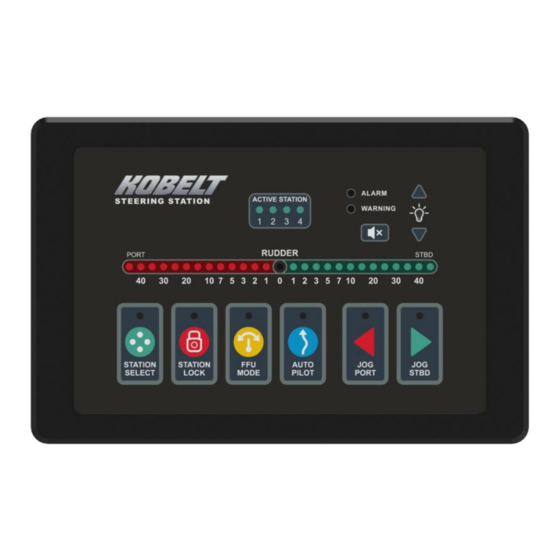
Page 87: Station Control
Kobelt Steering System Kobelt Manufacturing Co. Ltd. 9.2 S TATION ONTROL Figure 76 Head Picture Overview Table 22 Head Overview Table Name Colour Label Brightness Description Active Stations LED will be ON to show the station Green “1”, “2”, “3”, “4”... - Page 88 Kobelt Steering System Kobelt Manufacturing Co. Ltd. Also, can be disabled. Station select None, positioned Green by station select Adjustable Solid ON if the head is selected button Station lock None, positioned by station lock Adjustable Solid ON if the head is locked...
- Page 89 Kobelt Steering System Kobelt Manufacturing Co. Ltd. 9.2.1 Station Select Button Station Select Function: • By pressing the Station Select button, active Station transfers between the stations. After the station is active, the Station Select LED will be solid ON.
- Page 90 Kobelt Steering System Kobelt Manufacturing Co. Ltd. 9.2.3 Jog Buttons Jog Control Function: • By pressing the Jog Port or Jog Stbd button in the Normal mode from an active Station, system will start the jog control and move the rudder following the Jog Speed, which is saved in the configuration. The Jog Port or Jog Stbd LED will be ON when the button is pressing and be OFF after released.
-
Page 91: Steering Control
Kobelt Steering System Kobelt Manufacturing Co. Ltd. [Rudder Angle/Order (Style 2)]: Rudder Angle is indicated by a single bright LED, Rudder Order is indicated as strip of dimmer LEDs extending out from center. • Modes of operation: [Normal Operation]: Normal operation, shows the Rudder Order and Rudder Angle [FFU Alignment Mode]: Refer section 9.4.2.2. - Page 92 Kobelt Steering System Kobelt Manufacturing Co. Ltd. 9.4.1 Jog Control The general operation of Jog Control in the Voyager System is very simple. The system accepts commands from the operator or the autopilot to move the rudder to port or starboard at a fixed speed governed by the steering system's hydraulics.
- Page 93 Kobelt Steering System Kobelt Manufacturing Co. Ltd. 9.4.1.5 Two-speed Operation Two-speed operation occurs when the user operates the jog input devices attached to the system controlling the rudder in the direction corresponding to the jog input at a fixed maximum speed.
-
Page 94: Local Emergency Backup Control
Kobelt Steering System Kobelt Manufacturing Co. Ltd. 9.4.2 Full Follow-Up 9.4.2.1 FFU Mode Button FFU Mode Function: • By pressing the FFU Mode button in the Normal Mode from the active station, the FFU Alignment process will start, refer the section 9.4.2.2 for the detail. -
Page 95: Autopilot Control
Kobelt Steering System Kobelt Manufacturing Co. Ltd. Figure 77: System with Local Emergency Backup Control 9.6 A UTOPILOT ONTROL The system cannot detect if an autopilot faults or goes offline. It is important to detect this and report to the operator that the autopilot has released control of steering the vessel. - Page 96 Kobelt Steering System Kobelt Manufacturing Co. Ltd. 9.6.1 Autopilot Button Autopilot Mode Function (when Pressed and Released): • By pressing the Autopilot Button in the Normal Mode from the active station, Autopilot mode enters in the Standby state. In the Standby state, the Autopilot Indicator will flash to inform the operator that the Voyager system is waiting for the Autopilot command.
-
Page 97: Autopilot Settings
Kobelt Steering System Kobelt Manufacturing Co. Ltd. 9.7 A UTOPILOT ETTINGS 9.7.1 Autopilot Auto Disengage Figure 78: Autopilot Automatic Disengage State Diagram The autopilot setting “Auto Disengage” means the autopilot mode exits when a steering command is read from the wheel or jog lever. -
Page 98: Figure 79: Autopilot Manual Disengage State Diagram
Kobelt Steering System Kobelt Manufacturing Co. Ltd. 9.7.2 Autopilot Manual Disengage Figure 79: Autopilot Manual Disengage State Diagram The autopilot setting “Manual Disengage” means the Autopilot Mode exits only when the Autopilot button is pressed on the active Head. The system gives full control of the valves to the autopilot input commands. While in Autopilot Mode the steering controls are not active and will only become active when Autopilot Mode is exited. -
Page 99: Virtual End-Stop
Autopilot Mode the user must press the Autopilot button. Autopilot Mode being disabled will be indicated by the Autopilot Indicator turning off. It is recommended that any required service work on a Kobelt product be performed by a factory authorized service representative. Please contact the nearest Kobelt authorized distributor for assistance. -
Page 100: Alarms
Kobelt Steering System Kobelt Manufacturing Co. Ltd. The system has configurable virtual end-stops that will stop the valve from being driven when the system's feedback input reaches the configured end-stop angle. These end-stops are intended for use with the Position Control Rudder orders from the FFU or the SBW Wheel. - Page 101 Supports SDHC/XC cards and up to 64 GB (Requires Special Formatting), these can be purchased from Kobelt. Off the shelf 32GB cards with FAT32 formatting will work without special formatting Inserting an SD card during operation requires the system to be power cycled to successfully mount the card.
-
Page 102: Maintenance
Kobelt Steering System Kobelt Manufacturing Co. Ltd. 10 M AINTENANCE 10.1 B ATTERY EPLACEMENT This section will provide a detailed guide on replacing the battery on the NGSS Controller. The NGSS Controller has an internal battery on the device (CR2032). This battery is needed for the real time clock to function correctly. - Page 103 Kobelt Steering System Kobelt Manufacturing Co. Ltd. 5. Remove the din rail clips from the housing 6. Ensure that you are properly ground at this point to guarantee no unwanted Electrostatic discharge onto the device. 7. Open the controller box backing making sure to start with the side with the “KNET” Connector and labeled “TOP”...
-
Page 104: Real Time Clock
LOCK The Kobelt Steering Controller has a real time clock that will continuously run from an additional internal battery. In the event the battery is discharged and is replaced the real time clock needs to be re-set to the current date and time. - Page 105 Kobelt Steering System Kobelt Manufacturing Co. Ltd. ITEM KOBELT PART # Male Network Terminator 6015-1011 Female Network Terminator 6015-1012 CR2032 Coin Battery 9870-0001 To purchase spare parts Contact Kobelt for list of parts numbers available rev A MNL-002.docx 105 of 126...
-
Page 106: Troubleshooting
The user must not attempt to repair the unit themselves. It is strongly recommended that any required service work on a Kobelt unit be performed by a factory authorized service representative. Please contact the nearest Kobelt authorized distributor for assistance. -
Page 107: Figure 84: Dual Rudder Main Monitoring Screen
Kobelt Steering System Kobelt Manufacturing Co. Ltd. Figure 84: Dual Rudder Main Monitoring Screen • Angle – Angle reading from the RFU source. This will show a “ – “ if there is a fault with the RFU reading •... -
Page 108: Figure 85: Rudder Feedback Screen
Kobelt Steering System Kobelt Manufacturing Co. Ltd. Figure 85: Rudder Feedback Screen • RFU x Type – what type of RFU is configured with the system: 1kOhm Pot 10kOhm Pot 4-20mA • RFU x Angle – The determined angle from the input after computing. -
Page 109: Figure 87: Ffu Status Screen
Kobelt Steering System Kobelt Manufacturing Co. Ltd. 11.1.4 FFU Status Screen Figure 87: FFU Status Screen • Head Mode – The state of the head that is being displayed. • Wheel state – A numeric indication of the Wheel state for diagnostics. -
Page 110: Figure 89: Controller Health Screen
Kobelt Steering System Kobelt Manufacturing Co. Ltd. • Jog Btn P/S – Jog port and jog starboard buttons drive signals from the displayed station. • NFU Input – The NFU programmed for the station being displayed, non-active stations display offline. -
Page 111: Figure 91: Controller And Head Version Screen
Kobelt Steering System Kobelt Manufacturing Co. Ltd. Always live. • AP P/S – The direction of Autopilot command, port or starboard. 11.1.8 Controller and Stations Version Screen • Controller – Firmware/Hardware information H/W: The hardware version of the Controller, “0” as the initial version. -
Page 112: Figure 92: Knet Io Status Screen
Kobelt Steering System Kobelt Manufacturing Co. Ltd. ▪ NFU Fault ▪ SBW Wheel ▪ Valve Current Fault Output 3 – Control System Fault ▪ Over Temperature ▪ Internal Voltage fault ▪ KNet Power Fault ▪ Flash or configuration fault Output 4 - Communications Fault ▪... -
Page 113: Figure 93: Fault Log Screen
Kobelt Steering System Kobelt Manufacturing Co. Ltd. Figure 93: Fault Log Screen 11.1.11 Fault Inspection Screens The Fault Inspector Screen shows details about alarms and warnings that have occurred. It is accessed by pressing the Enter button to select a fault in the Fault Log Screen. -
Page 114: Alarms, Warnings, And Cautions Corrective Actions
Kobelt Steering System Kobelt Manufacturing Co. Ltd. 11.2 A LARMS ARNINGS AUTIONS CORRECTIVE ACTIONS Table 25: Common Troubleshooting Problems Problem Cause Corrective Action (Issue Encountered) (What it Means) (What to Do) Product does not turn on Blown fuse or circuit breaker 1. - Page 115 Kobelt Steering System Kobelt Manufacturing Co. Ltd. Head x SBW wheel Input The communication problem Check Wheel connection between the station Failure between the Head and SBW and the wheel. (Loop Failure) wheel Replace drop cable or Y connector. 1. The FFU lever is wire break.
-
Page 116: Serial Number
11.3 S ERIAL UMBER • Assembly Serial Number The final product, as assembled by Kobelt has a serial number. rev A MNL-002.docx 116 of 126... -
Page 117: Usb Interface
Kobelt Steering System Kobelt Manufacturing Co. Ltd. Printed on a label on the front face of the Kobelt Steering Controller, or the back face of the Kobelt Steering Station 11.4 USB I NTERFACE 11.4.1 USB Port Connector Type: Mini USB Female B Qualified Technician use only. -
Page 118: Warranty
If any part is found to be defective, Kobelt will replace said part FOB the Kobelt factory provided that any such defective part is returned by the Buyer with freight and applicable forwarding charges prepaid by the Buyer. -
Page 119: Appendix A: Configuration Parameters
Kobelt Steering System Kobelt Manufacturing Co. Ltd. 13 A A: C PPENDIX ONFIGURATION ARAMETERS ID Parameter Explanation Range Step Unit Default Number of Steering Number of Stations (Heads) in the 1…4 stations Stations Voyager System. Set the Station Control Strategy. - Page 120 Kobelt Steering System Kobelt Manufacturing Co. Ltd. Configure the NFU Input type. Options: 10 NFU Input [1] Disabled [2] 1 Speed [3] 2 Speed Configure the FFU Input type. Options: 11 FFU Input [1] Disabled [2] 1k Pot [3] 5k Pot [4] 10k Pot Configure the RAI/ROI LED strip style.
- Page 121 Kobelt Steering System Kobelt Manufacturing Co. Ltd. Change the deadband compensation used for Valve #1 for direction A. The deadband is the range of spool commands that is not great enough to 21 Valve #1 overcome spool friction Deadband 0.0…75.0 25.0...
- Page 122 Kobelt Steering System Kobelt Manufacturing Co. Ltd. [6] Very 100.0 Slow Change the deadband compensation used for Valve #2 for direction C. The deadband is the range of spool commands that is not great enough to 24 Valve #2 overcome spool friction Deadband 0.0…75.0...
- Page 123 Kobelt Steering System Kobelt Manufacturing Co. Ltd. This is only shown when the Valve Type is configured as Proportional Valve control. Rudder speed for fast- speed jogging. 31 Jog Fast- This is only shown when [Jog Speed] 70.0 Speed the Valve Type is …100.0...
- Page 124 Kobelt Steering System Kobelt Manufacturing Co. Ltd. [2] Hold for 1.0 seconds [3] Hold for 1.5 seconds [4] Hold for 2.0 seconds [5] Hold for 2.5 seconds [6] Hold for 3.0 seconds [7] Hold for 4.0 seconds [8] Hold for 5.0 seconds...
-
Page 125: Appendix B: Station Cutout Template
Kobelt Steering System Kobelt Manufacturing Co. Ltd. 14 A B: S PPENDIX TATION UTOUT EMPLATE rev A MNL-002.docx 125 of 126... - Page 126 Kobelt Steering System Kobelt Manufacturing Co. Ltd. rev A MNL-002.docx 126 of 126 Heiko Digitally signed by Heiko Epkens Epkens Date: 2023.05.18 09:20:22 -07'00'...
Need help?
Do you have a question about the 6300-0100 and is the answer not in the manual?
Questions and answers