Table of Contents
Advertisement
Quick Links
Advertisement
Table of Contents

Related Manuals for Kobelt 6527


Summary of Contents for Kobelt 6527
- Page 1 6527 Electronic Actuator Owner’s Operation, Installation & Maintenance Manual...
- Page 2 6527 Actuator Kobelt Manufacturing Co. Ltd. NOTES RECORD DATA BEFORE INSTALLATION FOR FUTURE REFERENCE Model #: Serial #: Date of Purchase: Date of Installation: Rev A MNL-6527.docx Page 1 of 32...
-
Page 3: Table Of Contents
6527 Actuator Kobelt Manufacturing Co. Ltd. ABLE OF ONTENTS Introduction ......................3 Contact ........................3 Safety .......................... 3 Product Description ....................5 Overview........................5 Technical Data ......................6 Model Configuration Key ................... 6 Installation ......................7 Mechanical ......................... 7 Control Cable ......................7 Electrical ........................ -
Page 4: Introduction
This document is intended to clearly present comprehensive product data and provide technical information to assist the end user in design applications. Kobelt reserves the right, without notice, to change the design, or construction, of any products and to discontinue or limit distribution of any products. - Page 5 Ensure that all power sources are locked out prior to performing work. Pinch Points: The 6527 actuator contains pinch points, which can cause bodily harm. Ensure that hands and fingers remain clear of the pinch points when performing work.
-
Page 6: Product Description
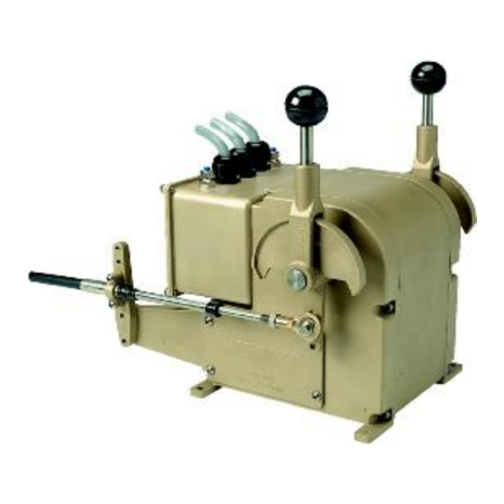
The Kobelt 6527 actuator is an electro-mechanical actuator that converts rotary motion from a DC motor to produce linear motion on a push/pull cable via the output lever. The 6527-S version has onboard electronics to control the motion and is connected to the Mighty Mariner propulsion control system via a CANbus interface. -
Page 7: Technical Data
Specified at maximum ambient temperature (55 At 25 C ambient temperature ODEL ONFIGURATION The 6527 actuator is manufactured in two versions: 6527-S Mighty Mariner version with onboard electronics 6527 Basic version with positioning motors and feedback potentiometers only Please ensure you refer to the correct sections of this manual for technical assistance Rev A MNL-6527.docx... -
Page 8: Installation
3.2.1 Hardware The 6527 actuator can be used with either 30 series or 40 series control cable. Kobelt Manufacturing does not recommend solid core cables if bends are present in the cable routing. A solid core cable would consist of a single wire that is too stiff. Multi-stranded cores are more flexible and therefore generates less friction during operation. - Page 9 For applications that require accurate positioning, a tie rod with rod ends is recommended over a push/pull cable. For terminating the cables Kobelt recommends a ball rod end. Rod ends are self-aligning and therefore minimize friction and binding. When installing hardware to the cable end, do not twist the core. If required, use a pair of pliers to hold the cable core from turning while installing the terminating hardware.
- Page 10 Avoid routing the cable near sources of heat, such as exhaust pipes. 3.2.3 Cable Connection The 6527 actuator has a lever mechanism for actuating the clutch and the throttle. Consult the figure at left to select the correct function.
- Page 11 (C). When connecting the actuating end of the cable to a spool valve such as the Kobelt 4605 servo cylinder, maximum cable life and efficiency is achieved when the cable is aligned with the lever in two planes.
-
Page 12: Electrical
3.3.1 Mighty Mariner System The 6527-S actuator is equipped with three cable glands with which to make the electrical connections. Use 0.20 inch [5 mm] to 0.47 inch [12 mm] OD cable with 18 AWG conductors for external connections to the engine controller. The cable must be twisted pair and shielded to protect signal integrity. - Page 13 3.3.1.1 Synchronizer/Tachometer Connection The Synchronizer sensor is realized with a three-wire proximity switch connected directly to the 6527-S as shown in Error! Reference source not found.the figure below. Figure 5: Synchronizer Pickup Wiring Diagram Table 7: Tachometer Port Connector SYNCHRO PORT...
- Page 14 6527 Actuator Kobelt Manufacturing Co. Ltd. 3.3.1.2 Shaft Brake/Neutral Safety Connection The Shaft Brake/Neutral Safety Output is a set of normally open contacts that close when the Clutch is in the neutral position. Configuring the output for Shaft Brake or Neutral Safety is done using external relays and protection diodes.
- Page 15 Neutral Safety Switch Bypass: A bypass for the neutral safety switches must be available to start the engines if the control system has failed. Check All Connections: Improper wiring connections may result in damage to the 6527-S Electronic Actuator. Rev A MNL-6527.docx...
- Page 16 Kobelt Manufacturing Co. Ltd. 3.3.2 6525 System The 6527 basic actuator for use with the 6525 system does not have a circuit board and therefore has a different wiring scheme. Consult the diagram below to connect the actuator correctly: Table 9: 6527 Actuator Terminations...
-
Page 17: Commissioning
DJUSTMENT These adjustments should only be performed by qualified personnel, and only while the vessel is at dock. Turn OFF the power to the 6527-S prior to adjusting the trimpots or DIP switches. Remove the enclosure cover Use a non-conductive flathead screwdriver to adjust the trimpots or DIP switches. - Page 18 6527 Actuator Kobelt Manufacturing Co. Ltd. Follow the table below to set the DIP switch correctly: Table 10: DIP Switch Configuration SW 1 Function FUNCTION POSITION POSITION PORT STBD PORT/STBD ACTUATOR ACTUATOR ACTUATOR ASSIGMENT THROTTLE ACTUATOR NORMAL REVERSE TRAVEL DIRECTION...
- Page 19 4.2.3 Stroke Adjustment The 6527-S actuator is equipped with manual overrides and one trim pot per side to adjust the stroke. The actuator does not have an internal resilient link. The stroke must, therefore, be adjusted precisely to suit the device being controlled.
-
Page 20: Functional Test
The Functional Test should be carried out while the vessel is still at dock. PERATION ANUAL VERRIDE The 6527 has a provision to permit manual control over the actuator functions should a power failure or actuator failure occur. Reference the... -
Page 21: Maintenance
6527 Actuator Kobelt Manufacturing Co. Ltd. AINTENANCE REVENTATIVE AINTENANCE • Quarterly (4 times per year) Visually inspect wire and cable insulation for splits or damage. Ensure there is no visible corrosion on the unit. • Every 2 years Lubricate gears Inspect push/pull cable Confirm cable glands are secured to cables. -
Page 22: Potentiometer Connection
6527 Actuator Kobelt Manufacturing Co. Ltd. Rotate the potentiometer bracket until the meter reads half of the rated output (~2500 ohms for a 5K potentiometer) Tighten the two locking screws and replace the cover. Notes: Due to variations in potentiometer ranges,... -
Page 23: Lubrication
The spare parts kept on hand will depend on the severity of the service. The User should monitor the condition of their actuator to predict necessary spare parts and ensure they are on hand when needed. As a minimum Kobelt recommends keeping the following parts for each actuator in service:... -
Page 24: Troubleshooting
6505 manual or the Mighty Mariner System Manual before contacting Kobelt for assistance. If the steps do not resolve your issue, please reach out to either Kobelt directly or our Dealers in your area. Rev A MNL-6527.docx... -
Page 25: Warranty
If any part is found to be defective, Kobelt will replace said part FOB the Kobelt factory provided that any such defective part is returned by the Buyer with freight and applicable forwarding charges prepaid by the Buyer. -
Page 26: Appendix A: Installation Dimensions
6527 Actuator Kobelt Manufacturing Co. Ltd. A: I PPENDIX NSTALLATION IMENSIONS Figure 10: 6527-S Installation Dimensions Rev A MNL-6527.docx Page 25 of 32... -
Page 27: Appendix B: Parts List
6527 Actuator Kobelt Manufacturing Co. Ltd. 10 A B: P PPENDIX ARTS Figure 11: 6527-S Parts List Rev A MNL-6527.docx Page 26 of 32... - Page 28 6527 Actuator Kobelt Manufacturing Co. Ltd. ITEM QTY PART NUMBER DESCRIPTION 6527-SUB ACTUATOR, SUB ASSEMBLY 6527-0004 COVER, SIDE 6527-0005 CONNECTION HOUSING 1010-0806 SCREW, RND HD PHL, 10-24 X 3/8, 18-8 SS 1002-0806 SCREW, SKT HEAD, 10-24 X 3/8, 18-8 SS...
- Page 29 6527 Actuator Kobelt Manufacturing Co. Ltd. Figure 12: 6527-SUB Parts List Rev A MNL-6527.docx Page 28 of 32...
- Page 30 SPUR GEAR, 112T, 32DP, 1.0IN BORE, B-STYLE 6527-0015 WORM GEAR, 60T, 7.65TPI, B-STYLE, C87800 6527-0017 SHAFT, 5/8IN OD X 4.5625IN LG, AISI 303 6527-0018 SHAFT, 6527, WORM GEAR TRAIN 6524-0015 SHAFT, HANDLE 2030-0001 HANDLE KNOB, SPHERICAL, BLACK 6524-0013-1 POTENTIOMETER BRACKET...
- Page 31 6527 Actuator Kobelt Manufacturing Co. Ltd. Figure 13: 6527-1028R & 6527-1028L ITEM QTY PART NUMBER DESCRIPTION 6527-0012A MOTOR BRACKET, RIGHT 6524-0019 WORM, 0.1307IN PITCH X .576IN OD, AISI C12L14 1012-0606 SCREW, PAN HD, PHL DRIVE, 6-32 x 3/8IN, 18-8 SS MOTOR-14201 MOTOR, 24VDC, 10-OZ-IN, 3330 RPM, 1.79A...
- Page 32 Kobelt Manufacturing Co. Ltd. 8238 129th Street Surrey, British Columbia, Canada, V3W 0A6 Sales Tel: +1-604-572-3935 Fax: +1-604-590-8313 Email: sales@kobelt.com Website: www.kobelt.com Made in Canada / Printed in Canada...
Need help?
Do you have a question about the 6527 and is the answer not in the manual?
Questions and answers