
Subscribe to Our Youtube Channel
Related Manuals for Kobelt 7195


Summary of Contents for Kobelt 7195
- Page 1 7195 Stacked Long Handle FFU Lever Owner’s Operation, Installation & Maintenance Manual March 2020 (Rev A)
- Page 2 7195 Stacked Long Handle FFU Lever Kobelt Manufacturing Co. Ltd. NOTES RECORD DATA BEFORE INSTALLATION FOR FUTURE REFERENCE Model #: Serial #: Date of Purchase: Date of Installation: Rev A MNL-7195 2 of 20...
-
Page 3: Table Of Contents
7195 Stacked Long Handle FFU Lever Kobelt Manufacturing Co. Ltd. ABLE OF ONTENTS Introduction ......................4 Contact ........................4 Compliant Use ......................4 Copyrights & Trademarks ..................4 Safety ........................5 Safety Alerts ......................5 Notice to Installer ....................5 Product Hazards ....................... -
Page 4: Introduction
Kobelt reserves the right, without notice, to change the design, or construction, of any products and to discontinue or limit distribution of any products. Kobelt also reserves the right to change, or update, without notice, any technical information contained within this document. -
Page 5: Safety
7195 Stacked Long Handle FFU Lever Kobelt Manufacturing Co. Ltd. AFETY AFETY LERTS Throughout this manual, the following symbols, and their accompanying explanation, are used to alert the user to special instructions concerning a service or operation that may be hazardous if performed incorrectly or carelessly. -
Page 6: Product Hazards
7195 Stacked Long Handle FFU Lever Kobelt Manufacturing Co. Ltd. RODUCT AZARDS Disconnect Power: Turn off power at distribution panel before beginning installation to protect installer from electrical hazards. Voltage and Current Compatibility: Confirm that the power source is compatible with the maximum voltage and current ratings of this product variant, including the potentiometer ratings. -
Page 7: About The Stacked Long Handle Ffu Lever
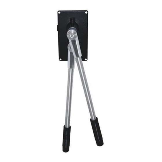
ANDLE EVER The Kobelt 7195 Stacked Long Handle FFU Lever is used as an input to Full Follow Up (FFU) electronic steering systems. The operator can maneuver the vessel by moving the lever port or starboard to adjust its internal potentiometer. The Stacked FFU Lever Controller can be used for steering applications, other marine applications, or industrial installations. -
Page 8: Installation
The Stacked Long Handle FFU Lever has two terminal blocks for external field connections. Use them for connection to the steering system interface on the vessel. The product’s terminal blocks contain the following connections and related functions: Table 2: 7195 Top Handle Terminal Block Connections Position Signal Name... - Page 9 7195 Stacked Long Handle FFU Lever Kobelt Manufacturing Co. Ltd. Figure 2: 7195 Internal Wiring and Connection Diagram NOTE: Only Pot 1 is installed on single pot product variants. The operating direction of the potentiometers in relation to the Stacked Long Handle FFU Lever handles is shown in Figure 3.
- Page 10 7195 Stacked Long Handle FFU Lever Kobelt Manufacturing Co. Ltd. Figure 3: 7195 Potentiometer Direction Diagram Rev A MNL-7195 10 of 20...
-
Page 11: Commissioning
Ensure that the rear cover is installed and secured before powering on the 7195. • Confirm that the electrical connections to the 7195 have been made. UNCTIONAL The Functional Test should be carried out while the vessel is still at dock and before it is taken out to sea after installation has been completed. -
Page 12: Operation
Kobelt Manufacturing Co. Ltd. PERATION The standard configuration of the Kobelt 7195 Stacked Long Handle FFU Lever contains a total of two (2) potentiometers, one (1) for each lever. The -PP variant contains two (2) potentiometers for each lever, for a total of four (4). Operating the Stacked Long Handle FFU Lever allows the hydraulic steering gear to move in the desired direction. -
Page 13: Maintenance
When purchasing replacement parts refer to Appendix B: Parts List at the back of this manual for Kobelt component Part Numbers. It is recommended that any required service work on a Kobelt unit be performed by a factory authorized service representative. Please contact the nearest Kobelt authorized distributor for assistance. -
Page 14: Troubleshooting
If you encounter problems with the operation of your product, please refer to the trouble- shooting suggestions before contacting Kobelt for assistance. If the steps below do not resolve your issue, please reach out either Kobelt directly or our Dealers in your area. Table 4: Common Solutions... -
Page 15: Warranty
If any part is found to be defective, Kobelt will replace said part FOB the Kobelt factory provided that any such defective part is returned by the Buyer with freight and applicable forwarding charges prepaid by the Buyer. -
Page 16: Appendix A: Installation Dimensions
7195 Stacked Long Handle FFU Lever Kobelt Manufacturing Co. Ltd. 10 A A: I PPENDIX NSTALLATION IMENSIONS Figure 5: 7195 Installation Dimensions Rev A MNL-7195 16 of 20... -
Page 17: Appendix B: Parts List
7195 Stacked Long Handle FFU Lever Kobelt Manufacturing Co. Ltd. 11 A B: P PPENDIX ARTS Figure 6: 7195 Parts Diagram Rev A MNL-7195 17 of 20... - Page 18 7195 Stacked Long Handle FFU Lever Kobelt Manufacturing Co. Ltd. Table 5: 7195 Parts List Model Series: 7195 Part No.: 7195-C ITEM DESCRIPTION Body - Chrome 7195-0001-K Handle - Chrome 7195-0002-K Bracket 7195-0003 7195-0004 Shaft – long 7195-0005 Shaft – short 7195-0006 Spacer –...
- Page 19 7195 Stacked Long Handle FFU Lever Kobelt Manufacturing Co. Ltd. Page Intentionally Left Blank Rev A MNL-7195 19 of 20...
- Page 20 Kobelt Manufacturing Co. Ltd. 8238 129th Street Surrey, British Columbia, Canada, V3W 0A6 Sales Tel: +1-604-572-3935 Fax: +1-604-590-8313 Email: sales@kobelt.com Website: www.kobelt.com Made in Canada / Printed in Canada...
Need help?
Do you have a question about the 7195 and is the answer not in the manual?
Questions and answers