Sign In
Upload
Manuals
Brands
Kobelt Manuals
Controller
6300-0100
Kobelt 6300-0100 Manuals
Manuals and User Guides for Kobelt 6300-0100. We have
1
Kobelt 6300-0100 manual available for free PDF download: Owner's Operation, Installation & Maintenance Manual
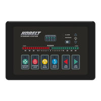
Kobelt 6300-0100 Owner's Operation, Installation & Maintenance Manual (126 pages)
Brand:
Kobelt
| Category:
Controller
| Size: 4.41 MB
Table of Contents
Table of Contents
3
Introduction
8
Contact
8
Compliant Use
8
Copyrights & Trademarks
8
Safety
9
Safety Alerts
9
Notice to Installer
9
Product Hazards
10
Scope
11
Terminology and Definitions
12
Stations
12
Kobelt Steering System Overview
13
System Description
13
Figure 1: Single Rudder Steering System Block Diagram (Simplified)
14
Figure 2:Dual Rudder Steering System Block Diagram (Simplified)
15
System Features
16
Figure 3: Steering System Block Diagram Render
16
Controller
17
Steering Station
17
Technical Specifications
18
Table 1: Technical Specifications Controller and Head
18
Installation
19
Location Requirements
19
Mechanical
19
Additional Components
19
Compass Safe Distance
20
EMC Installation Guidelines
20
Electrical Considerations for Installation
21
Figure 4: KNET Ferrite Choke
21
Figure 5: Wheel Connector EMC Clamp Diagram
21
Table 2: Knet Cable Properties
22
Table 3: Knet Network Properties
22
Controller Field Wiring Connections
23
Figure 6 Controller Picture Overview
23
Table 4 Controller Overview Table
23
Figure 7: the Controller Wiring
24
Figure 8: Electrical Connector for Valve Power
24
Figure 9: Electrical Connector for Valve #1 (Channels A/B)
25
Table 5: Valve Power Connector
25
Table 6: Valve #1 Connector
25
Figure 10: Electrical Connector for Valve #2 (Channels C/D)
26
Table 7: Valve #2 Connector
26
Figure 11: Valve Wiring for Solenoid Valves (4-Wire)
27
Figure 12: Valve Wiring for Solenoid Valves (Common Negative)
27
Figure 13: Valve Wiring for Solenoid Valves (Common Positive)
27
Figure 14: Electrical Connector for RFU #1
29
Table 8: RFU #1 Connector
29
Figure 15: Electrical Connector for RFU #2
30
Table 9: RFU #2 Connector
30
Figure 16: RFU Wiring for 1 Rudder with 1 Potentiometer Sensor
31
Figure 17: RFU Wiring for 2 Rudders with 2 Potentiometer Sensors
31
Figure 18: RFU Wiring for 1 Rudder with 1 Current Sensor
32
Figure 19: RFU Wiring for 2 Rudders with 2 Current Sensors
33
Figure 20: Electrical Connector for Autopilot Interface
33
Table 10: Autopilot Connector
33
Figure 21: Autopilot Wiring for Autopilot with Solenoid Valve Outputs (Sinking or Sourcing Outputs)
34
Figure 22: Autopilot Wiring for Autopilot with Reversing Pump Outputs
34
Figure 23: Knet Male Connector Pinout for the Controller
34
Table 11: Knet Network Connector
34
Figure 24: Electrical Connector for External Alarm Buzzer & Alarm Dry Contact
35
Table 12: List of Alarm Dry Contact States
35
Table 13: Alarm Output Connector
35
Figure 25: Wiring of External Buzzer
36
Figure 26: Utility Digital Inputs
36
Figure 27: Utility Digital Outputs
37
Steering Station Field Wiring Connections
38
Figure 28: Head Input/Output Connections
38
Figure 29: Knet Male Connector Pinout for the Station
38
Table 14: Station Back Connections
38
Figure 30: SBW Wheel Female Connector Pinout
39
Table 15: Knet Network Connector
39
Table 16: SBW Wheel Connector
39
Figure 31: Electrical Connector for FFU Input Device
40
Table 17: FFU Connector
40
Figure 32: FFU Wiring with 1 Potentiometer Sensor
41
Figure 33: Electrical Connector for NFU Interface
42
Figure 34: NFU Wiring for 1-Speed Jog Lever (Common Negative)
42
Table 18: NFU Connector
42
Figure 35: NFU Wiring for Two-Speed Jog Lever (8-Wire)
43
Figure 36: NFU Wiring for Two-Speed Jog Lever (Common Negative)
43
Figure 37: Brightness Wiring for Dimming Potentiometer
44
Figure 38: Electrical Connector for External Alarm Buzzer & Alarm Dry Contact
44
Table 19: List of Alarm Dry Contact States
44
Figure 39: Wiring of External Buzzer
45
Table 20: Alarm Output Connector
45
Configuration
46
Configuration Checklist
46
Menu Structure Overview
49
Figure 40: Controller Buttons for Navigation and Configuration
49
Table 21 HMI Keypad Overview
49
Figure 41: Root Menu Structure
50
Figure 42: Password Select Screen
51
Figure 43: Steering System Configuration Menu Overview
52
Figure 44: Steering System Setup
52
Figure 45: Configuration Management Screen
53
Figure 46: Factory Reset Confirmation Screen
54
Figure 47: Restore Configuration Confirmation Screen
54
Figure 48: Save Configuration Confirmation Screen
55
Figure 49: Success or Failed Screen
55
Figure 50: Set Date/Time Screen
56
Figure 51: Set Valve Type Screen
56
Figure 52: Set FRU Type Screen
56
Figure 53: Setup Jog Control Screen
57
Figure 54: Autopilot Type Settings
58
Figure 55: Number of Stations Screen
59
Figure 56: Station Activation Screen
59
Figure 57: Steering Station Configuration Menu Overview
60
Figure 58: Station Select Screen
60
Figure 59: Station Setup Screen
61
Figure 60: Set Station Name Screen
61
Figure 61: Steering Wheel Setup Screen
62
Figure 62: NFU Input Type Screen
64
Figure 63: FFU Input Screen
64
Figure 64: LED Strip Style Screen
65
Figure 65: Station Backlight Colour Screen
65
Figure 66: Setup Rudder(S)
66
Figure 67: Rudder/Valve Setup Screen
66
Figure 68: Toe in Configuration
67
Figure 69: Toe out Configuration
67
Configuration Parameters
68
Default Configuration
68
Commissioning
69
Commissioning Checklist
69
Steering Station ID Selector Interface
73
Figure 70: Station ID Selector Location
73
Calibration and Adjustment
74
Figure 71:Valve Dead-Band Graph
75
Figure 72: RFU Calibration Screens
77
Figure 73: Entering Active Menu
79
Figure 74: Active Menu Overview
79
Figure 75: Position Control Menu Screen
80
Functional Test
82
Operation
86
Station Transfer Mode
86
Station Control
87
Figure 76 Head Picture Overview
87
Table 22 Head Overview Table
87
Steering Control
91
Steering Modes
91
Table 23: List of Steering Modes
91
Local Emergency Backup Control
94
Autopilot Control
95
Figure 77: System with Local Emergency Backup Control
95
Autopilot Settings
97
Figure 78: Autopilot Automatic Disengage State Diagram
97
Figure 79: Autopilot Manual Disengage State Diagram
98
Virtual End-Stop
99
Figure 80: Autopilot Always Live State Diagram
99
Alarms
100
SD Card
100
Figure 81 - Acknowledge Alarm Button
100
Figure 82 - Alarm & Warning Log Page
100
Maintenance
102
Battery Replacement
102
Real Time Clock
104
Preventative Maintenance
104
Recommended Spare Parts
104
Table 24: Recommended Spares
104
Troubleshooting
106
Controller Information Screens
106
Figure 83: Single Rudder Main Monitoring Screen
106
Figure 84: Dual Rudder Main Monitoring Screen
107
Figure 85: Rudder Feedback Screen
108
Figure 86:Valves Status Screen
108
Figure 87: FFU Status Screen
109
Figure 88: Jog Status Screen
109
Figure 89: Controller Health Screen
110
Figure 90: Autopilot Status Screen
110
Figure 91: Controller and Head Version Screen
111
Figure 92: Knet IO Status Screen
112
Figure 93: Fault Log Screen
113
Figure 94: Fault Inspector Screen
113
Alarms, Warnings, and Cautions Corrective Actions
114
Table 25: Common Troubleshooting Problems
114
Serial Number
116
Table 26: Alarm Indicator Error Codes
116
USB Interface
117
Figure 95: Mini USB Female B Connector
117
Warranty
118
Appendix A: Configuration Parameters
119
Appendix B: Station Cutout Template
125
Advertisement
Advertisement
Related Products
Kobelt 6300-0200
Kobelt 6505
Kobelt 6527
Kobelt 600-031
Kobelt 600-032
Kobelt 600-032SS
Kobelt 6506
Kobelt 6555
Kobelt 7171
Kobelt 7195
Kobelt Categories
Industrial Equipment
Controller
Water Pump
Measuring Instruments
Control Unit
More Kobelt Manuals
Login
Sign In
OR
Sign in with Facebook
Sign in with Google
Upload manual
Upload from disk
Upload from URL