
Related Manuals for Kobelt 6505


Summary of Contents for Kobelt 6505
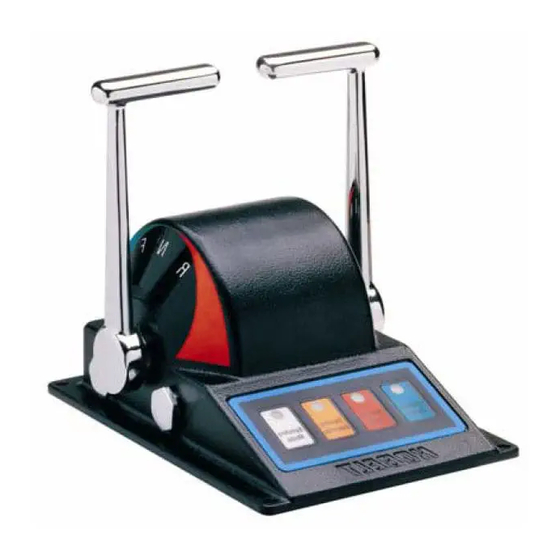
- Page 1 6505 Electronic Control Head Owner’s Operation, Installation & Maintenance Manual Kobelt Manufacturing Co. Ltd.
- Page 2 6505 Control Head Kobelt Manufacturing Co. Ltd. NOTES RECORD DATA BEFORE INSTALLATION FOR FUTURE REFERENCE Model #: Serial #: Date of Purchase: Date of Installation: Rev A mnl6505.docx 2 of 18...
-
Page 3: Table Of Contents
6505 Control Head Kobelt Manufacturing Co. Ltd. Table of Contents Introduction ........................4 Contact ............................4 Safety ............................4 1.2.1 Safety Alerts .......................... 4 1.2.2 Notice to Installer ........................4 1.2.3 Product Hazards ........................5 Product Description .......................6 Overview............................ 6 Technical Data ........................... 7 Model Configuration Key ...................... -
Page 4: Introduction
This document is intended to clearly present comprehensive product data and provide technical information to assist the end user in design applications. Kobelt reserves the right, without notice, to change the design, or construction, of any products and to discontinue or limit distribution of any products. -
Page 5: Product Hazards
Ensure that all power sources are locked out prior to performing work. Pinch Points: The 6505 control head contains pinch points, which can cause bodily harm. Ensure that hands and fingers remain clear of the pinch points when performing work. -
Page 6: Product Description
The Kobelt 6505 compact electronic control head provides a 10-bit digital output, communicated via CANbus, that is proportional to the handle position. This output is used by Kobelt’s Mighty Mariner controller to control engine throttle, clutch engagement or propellor pitch. The handle also has three detent positions;... -
Page 7: Technical Data
6505 Control Head Kobelt Manufacturing Co. Ltd. ECHNICAL Handle Travel: • Neutral: detented • Clutch in: +/- 20 detented • Full travel: +/- 68 Output CANbus (132 ft [40m] maximum) Terminals 22-16 AWG, screw clamp type Ambient Temperature: 14°F…+122°F [-10 °C… + 50°C]... -
Page 8: Installation
Loctite 243. LECTRICAL The 6505 control head is equipped with two cable glands with which to make the electrical connections. Use 0.20 inch [5 mm] to 0.47 inch [12 mm] OD cable with 18 AWG conductors for external connections to the engine controller. -
Page 9: Dip Switch Settings
6505 Control Head Kobelt Manufacturing Co. Ltd. Table 1: Connector P2 termination Pin # Signal Conductor + VDC WHT 2 BLK 2 DATA+ WHT 1 DATA- BLK 1 SHIELD SHIELD The last control head must have a 120 ohm resistor between terminals 3 &... -
Page 10: Operation
6505 Control Head Kobelt Manufacturing Co. Ltd. PERATION The 6505 control head is equipped with four membrane buttons that enable the following functions: STATION SELECT permits the transfer of engine control to another station. On power-up, station control automatically is assigned to station 1 (main station). -
Page 11: Potentiometer Connection
6505 Control Head Kobelt Manufacturing Co. Ltd. 3. Locate the potentiometer in need of centering. 4. Connect a multimeter to the Pot – (white wire) and the Pot Wiper (green wire). Set the meter to read resistance. 5. Loosen the two locking set screws on the pinion gear with a 1/16-inch Allen key. -
Page 12: Recommended Spare Parts And Kits
The spare parts kept on hand will depend on the severity of the service. The User should monitor the condition of their control head to predict necessary spare parts and ensure they are on hand when needed. As a minimum Kobelt recommends keeping the following parts for each brake in service: 1. One friction kit 2. -
Page 13: Warranty
Buyer. Kobelt’s sole obligation to the Applicant will be to repair or replace the defective part with same or similar product, to a maximum value of the list price of the product or part. The Kobelt warranty does not cover labour charges, travel or any other associated expenses. -
Page 14: Appendix A: Installation Dimensions
6505 Control Head Kobelt Manufacturing Co. Ltd. A: I PPENDIX NSTALLATION IMENSIONS Rev A mnl6505.docx 14 of 18... -
Page 15: Appendix B: Parts List
6505 Control Head Kobelt Manufacturing Co. Ltd. B: P PPENDIX ARTS 6505-TB Rev A mnl6505.docx 15 of 18... - Page 16 COVER PLATE LARGE 6505-0004-S COVER PLATE, SMALL 6009-7840 CABLE GLAND, 1/2 NPT, .39 - .55 CORD, NYLON 6505-1001-CBOARD-P PCB ASSEMBLY - CONTROL HEAD 1012-0604 SCREW, PAN HD PHILLIPS, 6-32 X 1/4, 18-8 1012-0608 SCREW, PAN HD, PHL, #6-32 x 1/2, 18-8...
-
Page 17: Appendix C: Installation Cut-Out Template
6505 Control Head Kobelt Manufacturing Co. Ltd. C: I PPENDIX NSTALLATION EMPLATE Scale may not be exactly 1:1 due to PDF and printer scaling. Verify primary dimension with a ruler after printing and before using to cut. Reference Appendix A: Installation Dimensions , for the cut-out dimensions. - Page 18 Kobelt Manufacturing Co. Ltd. 8238 129th Street Surrey, British Columbia, Canada, V3W 0A6 Sales Tel: +1-604-572-3935 Fax: +1-604-590-8313 Email: sales@kobelt.com Website: www.kobelt.com Made in Canada / Printed in Canada...
Need help?
Do you have a question about the 6505 and is the answer not in the manual?
Questions and answers