
Related Manuals for Albion ART 22


Summary of Contents for Albion ART 22
- Page 1 Installation & Operating Manual ART 22 Fixed Orifice Double Regulating Valve Albion Valves (UK) Ltd www.albionvalvesuk.com Email: sales@albionvalvesuk.com Tel: 01226 729900 ART 22 Rev 1...
-
Page 2: Table Of Contents
Dedicated M & V confirmation 42mm & 54mm Flow Coefficient The flow rate can be calculated using the Kv value and a measured signal. Kv = Q*36 / √ ΔP Kvs = Q*36 / √ ΔPs Where Kv & Kvs = flow coefficient (m3/hr at 1 bar differential) Q - Flow rate (l/s) ΔP - Head loss attributable to valve (kPa) ΔPs - Differential pressure across tappings (signal) (kPa) Kv Values Size ½” L ½” ML ½” ¾” 1 ¼” 1 ½” 2” 0.53 0.74 13.4 18.7 30.1 ART 22 Rev 1... -
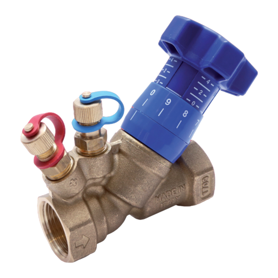
Page 3: Valve Features
¾” 1 ¼” 1 ½” 2” 0.62 19.0 22.1 42.3 Albion Valves (UK) Ltd recommend that any ART 22 FODRV are sized prior to installation to en- sure the correct valve selection. Valve Features • The ART 22 FODRV is manufactured in accordance with BS 7350. • The ART 22 is used for balancing the flow in heating, cooling and domestic water systems. • The ART 22 is a combined manual pre-setting valve with the following features: • Fixed measurement orifice;... -
Page 4: Regulating
• When the regulated position is achieved the double regulating feature is set by rotating a 3mm allen key in a CCW direction until resistance is met. The regulating feature is now set and the valve can be closed for isolation and then reopened to the previously set position. • This flow rate can be measured using a suitable differential manometer. This interfaces with the balancing valve through two sensors inserted in the binder test points placed before and after the valves fixed orifice plate. Flushing Control valves are sized to give good control over the system water and have therefore been designed with small, convoluted flow paths. These water ways may not allow adequate water velocities needed for flushing the system during the pre-commissioning stages of water treatment, even when fully open. In line with BSRIA recommendations, suitable consideration needs to be made as to how the removal of system debris can be achieved during the system flushing process. Regulating • To close the valve rotate the handle clockwise until it stops. Using the data reported in the attached diagrams, the flow can be regulated by rotating the handle counter-clockwise until the required flow rate is reached. • This flow rate can be measured using a suitable differential manometer. • This interfaces with the balancing valve through two sensors inserted in the binder points (Kvs) placed before and after the valve’s gauged diaphragm. • The main scale with values from 0 to 4 on the handle, indicates the turns for opening the obturator, while the second circular scale from 0 to 9 records the tenths of one turn. • The position of the handle at the required flow rate can be memorized using a 3 mm Allen Key. ART 22 Rev 1... -
Page 5: Approvals Classification
Approvals Classification • The valve is WRAS approved. • The valve is classified in accordance with PED 2014/68/EU as Sound Engineering Practice (SEP). Troubleshooting • If any maintenance is to be undertaken on the valve it is the responsibility of the installer to ensure the system is adequately drained and depressurized. • A full risk assessment should be undertaken prior to any works taking place. Warranty • For further details of Albion Valves (UK) Ltd warranty period, please refer to Albion Valves (UK) Ltd “Conditions of Sale” available on our website. ART 22 Rev 1... - Page 6 1/2” ART 22L DZR Fixed Orifice Double Regulating Valve 0.01 0.02 0.03 0.04 0.05 0.06 0.08 Flowrate l/s Signal / Flowrate Chart used to determine flowrate from signal measured across orifice Q = Kvs √ Δp Where Q = Flowrate l/s Δp = Signal kPa Kvs = Signal Co-efficient ART 22 Rev 1...
- Page 7 1/2” ART 22ML DZR Fixed Orifice Double Regulating Valve 0.02 0.03 0.04 0.05 0.06 0.08 Flowrate l/s Signal / Flowrate Chart used to determine flowrate from signal measured across orifice Q = Kvs √ Δp Where Q = Flowrate l/s Δp = Signal kPa Kvs = Signal Co-efficient ART 22 Rev 1...
- Page 8 1/2” ART 22 DZR Fixed Orifice Double Regulating Valve 0.04 0.05 0.06 0.08 Flowrate l/s Signal / Flowrate Chart used to determine flowrate from signal measured across orifice Q = Kvs √ Δp Where Q = Flowrate l/s Δp = Signal kPa Kvs = Signal Co-efficient ART 22 Rev 1...
- Page 9 3/4” ART 22L DZR Fixed Orifice Double Regulating Valve Flowrate l/s Signal / Flowrate Chart used to determine flowrate from signal measured across orifice Q = Kvs √ Δp Where Q = Flowrate l/s Δp = Signal kPa Kvs = Signal Co-efficient ART 22 Rev 1...
- Page 10 1” ART 22L DZR Fixed Orifice Double Regulating Valve 0.15 Flowrate l/s Signal / Flowrate Chart used to determine flowrate from signal measured across orifice Q = Kvs √ Δp Where Q = Flowrate l/s Δp = Signal kPa Kvs = Signal Co-efficient ART 22 Rev 1...
- Page 11 1.1/4” ART 22L DZR Fixed Orifice Double Regulating Valve Flowrate l/s Signal / Flowrate Chart used to determine flowrate from signal measured across orifice Q = Kvs √ Δp Where Q = Flowrate l/s Δp = Signal kPa Kvs = Signal Co-efficient ART 22 Rev 1...
- Page 12 1.1/2” ART 22L DZR Fixed Orifice Double Regulating Valve Flowrate l/s Signal / Flowrate Chart used to determine flowrate from signal measured across orifice Q = Kvs √ Δp Where Q = Flowrate l/s Δp = Signal kPa Kvs = Signal Co-efficient ART 22 Rev 1...
- Page 13 2” ART 22L DZR Fixed Orifice Double Regulating Valve Flowrate l/s Signal / Flowrate Chart used to determine flowrate from signal measured across orifice Q = Kvs √ Δp Where Q = Flowrate l/s Δp = Signal kPa Kvs = Signal Co-efficient ART 22 Rev 1...
- Page 14 Delivery We know that time is money, and when a priority project depends on a part you can trust Albion to deliver – next day for all orders placed before 4:00PM. Choice We may have started out with a single brass ball valve, but our range has grown substantially since and we now consider ourselves to be a ‘One Stop Shop’...
Need help?
Do you have a question about the ART 22 and is the answer not in the manual?
Questions and answers