Table of Contents
Advertisement
Quick Links
Universal OEM Signaling Controller
The design concepts and engineering details embodied in this manual, which are the property of MICRONOR
SENSORS, are to be maintained in strict confidence; no element or detail of this manual is to be spuriously used, nor
disclosed, without the express written permission of MICRONOR SENSORS. All rights are reserved. No part of this
publication may be reproduced, stored in a retrieval system, or transmitted in any form or by any means, electronic,
mechanical, photocopying, recording, or otherwise, without prior written permission from MICRONOR SENSORS.
MR380-0-UNI
Fiber Optic
Instruction Manual
DOC: 98-0380-32
Revision C dated 5/12/2023
Notice of Proprietary Rights
© Copyright 2023, MICRONOR SENSORS, INC.
Venture, CA, USA
MICRONOR SENSORS INC.
2085 Sperry Ave, Suite A-1
Ventura, CA 93003 USA
T (805) 389-6600
sales@MICRONOR.com
www.MICRONOR.com
Advertisement
Table of Contents

Related Manuals for Micronor MR380-0-UNI


Summary of Contents for Micronor MR380-0-UNI
- Page 1 SENSORS, are to be maintained in strict confidence; no element or detail of this manual is to be spuriously used, nor disclosed, without the express written permission of MICRONOR SENSORS. All rights are reserved. No part of this publication may be reproduced, stored in a retrieval system, or transmitted in any form or by any means, electronic, mechanical, photocopying, recording, or otherwise, without prior written permission from MICRONOR SENSORS.
- Page 2 Revision History Date Notes 2/10/2016 Initial Release 8/1/2016 Update for New Terminal Plug 10/20/2016 Added Explosive Atmosphere specification 3/7/2017 Added Extended Temperature model MR380-0-1E 9/27/2019 Added Updated MR380 Declaration of Conformity 5/12/2023 Update for MR380-0-UNI Universal Controller Page 2 of 16...
-
Page 3: Table Of Contents
Optical Connections to the MR380-0 Controller ............10 Electrical Connections To MR380-0 Controller ............11 Warranty Information....................... 13 Specifications ........................14 MR380-0-UNI Universal OEM Signaling Controller ........... 14 Reference Documents ..................... 15 MR380-0 OEM Controller Reference Drawing ............15 Figures Figure 1. -
Page 4: Product Description
When the switch is activated, little or no light is coupled back to the receiver. The MICRONOR Fiber Optic switches are immune to EMI/RFI and can be deployed at great distances from the electrical controller. Applications include: •... -
Page 5: Fiber Optic Controller Board
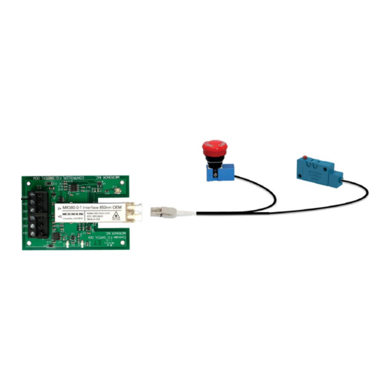
This universal PCB may be used in conjunction with many of the MICRONOR signaling devices. Figure 1. MR380 Fiber Optic Signaling Devices The MR380-0-UNI is intended for OEM applications where the PCB can be mounted into a suitable enclosure and where it is sufficiently protected from the environment such as water and dust or similar influences. -
Page 6: Figure 2. Block Diagram For A Mr380-0 Controller System
MR380-0-UNI Instruction Manual example, transmitting from OM1 fiber (62.5µm core) to OM2 fiber (50µm core) produces a loss of approximately 1.2dB, which is not a problem in most situations. In the MR380-0 controller, the transmit fiber is OS1 9/125µm single mode fiber. Since the core of the fiber is smaller than any other standard fiber, no losses are produced at this connection, no matter which standard fiber the rest of the system uses. - Page 7 MR380-0-UNI Instruction Manual which provides a known failure state. The controller then interprets events such as broken fiber, poor connection, high loss or a depressed switch as a failure or ‘EMERGENCY ON’. The photodetector outputs a logic signal to the remaining logic circuitry which then interprets high or low levels for the +5V digital and Open-Collector outputs.
-
Page 8: Initial Preparation
The PCB is an electronic Assembly and susceptible to ESD. Please use appropriate grounding and caution when handling the PCB. In the event of a damaged product, write or call your nearest MICRONOR AG sales office. Please retain the shipping container in case re-shipment is required for any reason. -
Page 9: Installation And Operation
Be sure to use proper fiber optic cleaming tools and procedures such as the MICRONOR MR321C Cleaning Kit. Improper tools and/or processes may damage or contaminate the optical interface. Mounting the MR380-0 Controller PCB The controller PCB should be mounted on 4 standoffs. -
Page 10: Optical Connections To The Mr380-0 Controller
MR380-0-UNI Instruction Manual Optical Connections to the MR380-0 Controller A duplex fiber optic cable is used to interconnect the sensor and controller. The sensor incorporates a 1.5m optical pigtail (or as specified by customer). If a longer connection to the controller is required, then a fiber optic extension cable may be used. -
Page 11: Electrical Connections To Mr380-0 Controller
MR380-0-UNI Instruction Manual Electrical Connections To MR380-0 Controller The may be unit is powered with any voltage between 5V and 24V DC. Current consumption is typ. 8mA at 5V DC and +12mA at 24V DC excluding any external load. CamdenBoss P/N CTB1301/6A (supplied) -
Page 12: Figure 7. External Relay Connection
MR380-0-UNI Instruction Manual Interfacing with an external Relay An external relay may be connected to the open-collector terminal (6). The maximum voltage allowed for this output is up to the power supply Voltage. If the pull-up resistor R8 is removed, then voltages exceeding the V Supply up to 48V are allowed. -
Page 13: Warranty Information
Send the product, transportation prepaid, to the indicated service facility. Repairs will be made and the product returned transportation prepaid. Repaired products are warranted for the balance of the original warranty period, or at least 90 days. MICRONOR AG resreves the option to either repair, or replace product. -
Page 14: Specifications
MR380-0-UNI Instruction Manual Specifications MR380-0-UNI Universal OEM Signaling Controller Functional States Example: MR386 Series Fiber Optic Microswitch For Normally Open (NO) Sensors - Plunger Up LED=Off, Logic Output=LO, Open Collector Outut=OFF LED=On, Logic Output=HI, Open Collector Output=ON Plunger Down (Normal State) -
Page 15: Reference Documents
MR380-0-UNI Instruction Manual Weight 25g (1oz) Specifications subject to change without notice Reference Documents Documents appear on the following pages. MR380-0 OEM Controller Reference Drawing Page 15 of 16... - Page 16 THE INFORMATION CONTAINED IN THIS MATERIAL SIZE DWG. NO. MR380-0 DRAWING IS THE SOLE PROPERTY OF MICRONOR INC. ANY REPRODUCTION IN FINISH PART OR AS A WHOLE WITHOUT THE NEXT ASSY USED ON WRITTEN PERMISSION OF MICRONOR INC. NOTES: UNLESS OTHERWISE SPECIFIED IS PROHIBITED.
Need help?
Do you have a question about the MR380-0-UNI and is the answer not in the manual?
Questions and answers