Table of Contents
Advertisement
Quick Links
The design concepts and engineering details embodied in this manual, which are the property of MICRONOR
LLC., are to be maintained in strict confidence; no element or detail of this manual is to be spuriously used, nor
disclosed, without the express written permission of MICRONOR LLC. All rights are reserved. No part of this
publication may be reproduced, stored in a retrieval system, or transmitted in any form or by any means,
electronic, mechanical, photocopying, recording, or otherwise, without prior written permission from
MICRONOR LLC.
MR380-1-3
Universal DIN Rail Controller
For Use with MR38X Series
Fiber Optic Signaling Sensors
Instruction Manual
Document: 98-0380-01
Revision E dated 5/7/2021
Notice of Proprietary Rights
© Copyright 2013-2021, Micronor LLC., USA
MICRONOR LLC.
900 Calle Plano, Suite K
Camarillo, CA 93012
USA
+1-805-389-6600
sales@micronor.com
www.micronor.com
For Support in Europe:
MICRONOR AG
Pumpwerkstrasse 32
CH-8105 Regensdorf
Switzerland
+41-44-843-4020
sales@micronor.ch
www.micronor.ch
Advertisement
Table of Contents

Related Manuals for Micronor MR380-1-3


Summary of Contents for Micronor MR380-1-3
- Page 1 LLC., are to be maintained in strict confidence; no element or detail of this manual is to be spuriously used, nor disclosed, without the express written permission of MICRONOR LLC. All rights are reserved. No part of this publication may be reproduced, stored in a retrieval system, or transmitted in any form or by any means, electronic, mechanical, photocopying, recording, or otherwise, without prior written permission from MICRONOR LLC.
- Page 2 5dB • Combined SM/MM Declaration of Conformity added 5/7/2021 • Updated text and logos to reflect change to Micronor LLC., a division of Photon Control • Updated MR380-1-3 and MR387 E-Stop System Functional Safety and Declaration of Conformity •...
-
Page 3: Table Of Contents
MR380-1-3 Installation ....................11 3.4.1. Electrical Connections .................... 11 3.4.2. MR380-1-3 and MR387 E-Stop System Start-Up & Performance Check ....12 4. Troubleshooting ..................13 Potential Issues & Solutions ..................13 Damaged in Shipment ....................14 5. Warranty Information ................15 6. - Page 4 Figure 2. Complete E-Stop Functional System Overview ..........6 Figure 3. MR386 Microswitch with MR380-1-3 Controller ..........6 Figure 4. MR380-1-3 Mounting Options: DIN Rail Mount versus Chassis Mount ..9 Figure 5. Panel Cut Out Dimensions and Assembly Hierarchy of E-Stop Switch ..10 Figure 6.
-
Page 5: Product Description
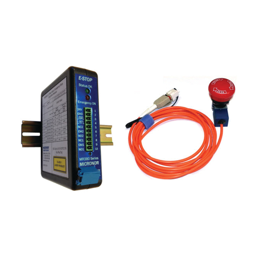
MR387 Fiber Optic Emergency Stop Switch Figure 1. MR387 Emergency Stop Switch with MR380-1-3 Controller The MR387 Fiber Optic Emergency Stop Switch paired with MR380-1-3 Controller provides a new, innovative emergency signaling detection that can be deployed in hazardous environments and over very long distances. -
Page 6: Mr386 Fiber Optic Microswitch
MR386 Fiber Optic Microswitch Figure 3. MR386 Microswitch with MR380-1-3 Controller The MR386 Fiber Optic Microswitch paired with the MR380-1-3 Controller provides a new, innovative signaling detection that can be deployed in difficult, hazardous environments and over very long distances. The Microswitch employs a photo interrupt scheme operating over a duplex 62.5/125μm fiber optic link that allows for reliable signal detection. -
Page 7: Fields Of Application
MR380-1-3 Instruction Manual There are two switch materials. The completely non–metallic version is designed to operate within an MRI environment where high magnetic fields would interfere with any electronic switch. The switch may be safely used within the MRI bore because it is immune to the magnetic field as well as invisible to the imaging process. -
Page 8: Standard Contents
MR380-1-3 Instruction Manual 2. Standard Contents MR380-1-3 Controller Module: • MR380-1-3 Controller Module • Phoenix Terminal Block (1879599) inserted as part of unit • Instruction Manual (this document, one soft copy supplied with each shipment) MR387 series Sensor: • MR387 sensor (confirm pigtail and/or connector interface as ordered) -
Page 9: Mr380-1-3 Controller Installation And Operation
The controller unit mounts on DIN rails as well as a single mounting clip. Both mounting schemes are shown below in Figure 4. Figure 4. MR380-1-3 Mounting Options: DIN Rail Mount versus Chassis Mount Connecting the MR380-1-3 Controller Module An LC Duplex optical cable is used to interconnect the sensor and controller. The sensor incorporates a 3m optical pigtail (or alternate length as specified by customer). -
Page 10: Mounting The Mr387 E-Stop Switch
MR380-1-3 Instruction Manual Mounting the MR387 E-Stop Switch When mounting the E-Stop switch into a panel, provide a cut-out as dimensionally shown below in Figure 5 and the Mechanical Reference Drawing in Section 9.2. Mushroom Push Panel Lock Washer Mounting... -
Page 11: Mr380-1-3 Installation
OPEN CLOSED The table above depicts the pinouts for the MR380-1-3 controller, and the state of each terminal when an E-stop switch is on or off. For powering the controller, +24 VDC is supplied to terminal 1 and grounded using terminal 2. For typical E-stop operation, connect to terminals 5 and 6 or terminals 8 and 9. -
Page 12: Mr380-1-3 And Mr387 E-Stop System Start-Up & Performance Check
MR380-1-3 Instruction Manual 3.4.2. MR380-1-3 and MR387 E-Stop System Start-Up & Performance Check Connect +24VDC supply and ground to the designated terminals on the controller module. Verify that the ‘POWER’ LED (green) is illuminated. If the E-Stop Switch is not connected, do so at this time and verify that the ‘EMERGENCY ON’... -
Page 13: Troubleshooting
The following are potential issues and recommended solutions when troubleshooting the MR380- 1-3 fiber optic system. For issues not listed, please contact Micronor Sales. Potential Issues & Solutions If the Instructions do not rectify the problem, then contact Micronor Sales for further assistance. Function Symptom Instructions ‘Power’... -
Page 14: Damaged In Shipment
Figure 9. LC Loopback MR380-1-3 Controller Check Damaged in Shipment In the event of a damaged instrument, write or call your nearest MICRONOR office in the U.S. A. Please retain the shipping container in case reshipment is required for any reason. -
Page 15: Warranty Information
5. Warranty Information Warranty MICRONOR LLC. warrants this product to be free from defects in material and workmanship for a period of 1 (one) year from date of shipment. During the warranty period we will, at our option, either repair or replace any product that proves to be defective. -
Page 16: Specifications
MR380-1-3 Instruction Manual 6. Specifications For additional clarification of parameters related to Functional Safety, Laser Safety, Explosive Atmospheres and CE Marking, consult Micronor document 93-0380-01, Declaration of Conformity. MR380-1-3 Controller Module Functional States As Applies to MR387 E-Stop Sensor Normal RESET (Up Position) -
Page 17: Mr387 Emergency Stop Switch
Red LED is ON Broken Fiber, Loss of Optical Signal, Digital 5V and 24V Outputs=LOW or Controller Failure Relay NC contacts=Open, Relay NO contacts=Closed For MR387 E-Stop Sensor + MR380-1-3 Universal Controller Functional Safety ISO 13849 Category 2 MTTF 4.14 E+06 hours (473.1 years) - Page 18 MR380-1-3 Instruction Manual Ingress Protection Pigtail Version=IP61, Panel Mount Housing=IP65 Mechanical Housing Aluminum body, anodized finish Durability 100,000 operations min. Physical Housing Dimension Consult Mechanical Reference Drawing Mounting Consult Mechanical Reference Drawing Unit Weight Sensor with 5 meter pigtail, 240 g (8.5 oz)
-
Page 19: Theory Of Operation
(62.5µm core) to OM2 fiber (50µm core) produces a loss of approximately 1.2dB, which is not a problem in most situations. In the MR380-1-3 controller, the transmit fiber is OS1 9/125µm single mode fiber. Since the core of the fiber is smaller than any other standard fiber, no losses are produced at this connection, no matter which standard fiber the rest of the system uses. -
Page 20: Functional Block Diagram
Controller Figure 10. Block Diagram for a MR380-1-3 Controller System The light source power is held constant under normal operating conditions allowing for a known system loss budget when designing a system. Additionally, the optics within the switch are designed to couple maximum light back into the receive fiber enabling the ability to create long distance systems and chain multiple switches. -
Page 21: Application Notes
8. Application Notes Determining System Loss Budget when Chaining Multiple Switches The MR380-1-3 controllers have the capacity to chain multiple switches in series, permitted that the additional losses fall within the optical system loss budget. Figure 11 illustrates a system using three MR387 switches in series. -
Page 22: Triggering Multiple Controllers With A Single E-Stop
Figure 12 demonstrates a system with one E-stop and two controllers, each with DPDT relay contacts, with an arbitrary distance between them. Figure 12. Example System With One MR387 E-Stop Triggering Two Remote MR380-1-3 Controllers Page 22 of 29... -
Page 23: Reference Documents
MR380-1-3 Instruction Manual 9. Reference Documents See following pages for these reference drawings and documents. MR380-1 Controller Reference Drawing MR387 E-Stop Reference Drawing (2 pages) MR380 Series Declaration of Conformity (3 pages) Page 23 of 29... - Page 27 Page 1 of 19...
- Page 28 Page 2 of 19...
- Page 29 Page 3 of 19...
Need help?
Do you have a question about the MR380-1-3 and is the answer not in the manual?
Questions and answers