Table of Contents
Advertisement
Quick Links
The design concepts and engineering details embodied in this manual, which are the property of MICRONOR INC.,
are to be maintained in strict confidence; no element or detail of this manual is to be spuriously used, nor disclosed,
without the express written permission of MICRONOR INC. All rights are reserved. No part of this publication may
be reproduced, stored in a retrieval system, or transmitted in any form or by any means, electronic, mechanical,
photocopying, recording, or otherwise, without prior written permission from MICRONOR INC.
MR380-0
Fiber Optic Signaling
OEM PCB Controller
Instruction Manual
DOC: 98-0380-300
Revision B3 dated 9/27/2019
Notice of Proprietary Rights
© COPYRIGHT 2016-2019, MICRONOR INC.
CAMARILLO, CALIFORNIA
UNITED STATES OF AMERICA
MICRONOR INC.
900 Calle Plano, Suite K
Camarillo, CA 93012 USA
T (805) 389-6600
F (805) 389-6605
sales@MICRONOR.com
www.MICRONOR.com
For Support in Europe:
MICRONOR AG
Pumpwerkstrasse 32
CH-8105 Regensdorf
Switzerland
T +41-44-843-4020
F +41-44-843-4039
sales@MICRONOR.ch
www.MICRONOR.com
Advertisement
Table of Contents

Related Manuals for Micronor MR380-0


Summary of Contents for Micronor MR380-0
- Page 1 MICRONOR INC. All rights are reserved. No part of this publication may be reproduced, stored in a retrieval system, or transmitted in any form or by any means, electronic, mechanical, photocopying, recording, or otherwise, without prior written permission from MICRONOR INC.
- Page 2 MR380-0 PCB Signaling OEM Controller Manual Revision History Date Notes 2/10/2016 Initial Release 8/1/2016 Update for New Terminal Plug 10/20/2016 Added Explosive Atmosphere specification 3/7/2017 Added Extended Temperature model MR380-0-1E 9/27/2019 Added Updated MR380 Declaration of Conformity Page 2 of 19...
-
Page 3: Table Of Contents
Figure 2. Block-Diagram MR380-0 Controller Board ............ 6 Figure 3. Keep LC Duplex connector ends protected when not in use ....... 8 Figure 4. Dimensions of MR380-0 Controller PCB ............8 Figure 5. Make optical connection using LC-Duplex optical connector ....... 9 Figure 6. -
Page 4: Product Description
When the switch is activated, little or no light is coupled back to the receiver. The MICRONOR Fiber Optic switches are immune to EMI/RFI and can be deployed at great distances from the electrical controller. Applications include: •... -
Page 5: Fiber Optic Controller Board
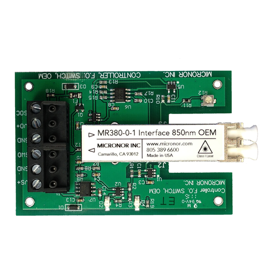
MR380-0 PCB Signaling OEM Controller Manual Fiber Optic Controller Board The MR380-0 Controller Board is intended for the OEM user in support of deployment of the various Fiber Optic Signaling products. The OEM PCB contains a stabilized transmitter and a sensitive optical receiver. -
Page 6: Functional Description
MR380-0 PCB Signaling OEM Controller Manual Functional Description The controller board sends a steady stream of optical pulses at approx. 150kHz to 300kHz frequency. The returned optical signal strength determines wether the electrical output is activated. When sufficient light is received, the outputs are activated. -
Page 7: Initial Preparation
The PCB is an electronic Assembly and susceptible to ESD. Please use appropriate grounding and caution when handling the PCB. In the event of a damaged product, write or call your nearest MICRONOR sales office. Please retain the shipping container in case re-shipment is required for any reason. -
Page 8: Installation And Operation
Be sure to use proper fiber optic cleaming tools and procedures such as the MICRONOR MR321C Cleaning Kit. Improper tools and/or processes may damage or contaminate the optical interface. Mounting the MR380-0 Controller PCB The controller PCB should be mounted on 4 standoffs. -
Page 9: Optical Connections To The Mr380-0 Controller
MR380-0 PCB Signaling OEM Controller Manual Optical Connections to the MR380-0 Controller A duplex fiber optic cable is used to interconnect the sensor and controller. The sensor incorporates a 1.5m optical pigtail (or as specified by customer). If a longer connection to the controller is required, then a fiber optic extension cable may be used. -
Page 10: Electrical Connections To Mr380-0 Controller
MR380-0 PCB Signaling OEM Controller Manual Electrical Connections To MR380-0 Controller The may be unit is powered with any voltage between 5V and 24V DC. Current consumption is typ. 8mA at 5V DC and +12mA at 24V DC excluding any external load. -
Page 11: Interfacing With An External Relay
MR380-0 PCB Signaling OEM Controller Manual Interfacing with an external Relay An external relay may be connected to the open-collector terminal (6). The maximum voltage allowed for this output is up to the power supply Voltage. If the pull-up resistor R8 is removed, then voltages exceeding the V Supply up to 48V are allowed. -
Page 12: Warranty Information
Send the product, transportation prepaid, to the indicated service facility. Repairs will be made and the product returned transportation prepaid. Repaired products are warranted for the balance of the original warranty period, or at least 90 days. MICRONOR INC. resreves the option to either repair, or replace product. -
Page 13: Specifications
MR380-0 PCB Signaling OEM Controller Manual Specifications MR380-0 OEM Signaling Controller Electrical Interface Description Specification Connector CamdenBoss P/N CTB1301/6A 6C, Screw-Type Terminal Plug, 5mm Contact Spacing Logic Output High: 4.5V min. (2k Ohm Load) Low: 0.25V max. Open Collector Output... - Page 14 MR380-0 PCB Signaling OEM Controller Manual Temperature Standard (MR380-0-1): -10°C to +65°C Extended (MR380-0-1E): -40°C to +70°C Humidity 0% to 85% RH (non-condensing) Ingress Protection IP00 (none) Vibration/Shock Performance depends on mounting. Consult factory when designing for high shock and vibration environment.
-
Page 15: Reference Documents
MR380-0 PCB Signaling OEM Controller Manual Reference Documents Documents appear on the following pages. MR380-0 OEM Controller Reference Drawing MR386 Switch Reference Drawing MR380 Declaration of Conformity Page 15 of 19... - Page 16 THE INFORMATION CONTAINED IN THIS MATERIAL SIZE DWG. NO. MR380-0 DRAWING IS THE SOLE PROPERTY OF MICRONOR INC. ANY REPRODUCTION IN FINISH PART OR AS A WHOLE WITHOUT THE NEXT ASSY USED ON WRITTEN PERMISSION OF MICRONOR INC. NOTES: UNLESS OTHERWISE SPECIFIED IS PROHIBITED.
- Page 17 DoC is issued under our sole responsibility and belongs to the following products: • Fiber optic switch and signaling system, consisting of: • MR380-0, MR380-1, MR380-2 or MR382-1, Controller • MR380 series Sensor, MR381/MR382/MR383/MR384/MR385/MR386/MR387 That the equipment is in conformity with the following relevant European Union harmonization legislation: •...
- Page 18 DoC is issued under our sole responsibility and belongs to the following products: • Fiber optic switch and signaling system, consisting of: • MR380-0, MR380-1, MR380-2 or MR382-1, Controller • MR380 series Sensor, MR381/MR382/MR383/MR384/MR385/MR386/MR387 That the equipment is in conformity with the following International (IEC) and North American requirements: •...
- Page 19 DoC is issued under our sole responsibility and belongs to the following products: • Fiber optic switch and signaling system, consisting of: • MR380-0, MR380-1, MR380-2 or MR382-1, Controller • MR380 series Sensor, MR381/MR382/MR383/MR384/MR385/MR386/MR387 That the equipment is in conformity with the following relevant EAEU harmonization legislation: •...
Need help?
Do you have a question about the MR380-0 and is the answer not in the manual?
Questions and answers