Table of Contents
Advertisement
Quick Links
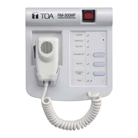
FIREMAN'S MICROPHONE
RM-300MF
Update history
HS0907
No.833-71-185-80
TABLE OF CONTENTS
GENERAL DESCRIPTION ......................................................................................................................... 1
NOTE ON REPAIR WORK SAFETY ......................................................................................................... 2
SPECIFICATIONS ..................................................................................................................................... 2
NOMENCLATURE AND FUNCTIONS ....................................................................................................... 3
WIRING DIAGRAM .................................................................................................................................... 5
• CPU PCB (1/2) .................................................................................................................................... 6
• CPU PCB (2/2) .................................................................................................................................... 7
• SW PCB .............................................................................................................................................. 8
• EMG SW PCB ..................................................................................................................................... 8
• CONNECTOR PCB ............................................................................................................................ 9
• HANDMIC PCB ................................................................................................................................... 9
• CPU PCB ......................................................................................................................................... 10
• SW PCB ............................................................................................................................................ 11
• EMG SW PCB ................................................................................................................................... 11
• CONNECTOR PCB .......................................................................................................................... 11
• HANDMIC PCB ................................................................................................................................. 11
• PARTS LIST ..................................................................................................................................... 11
EXPLODED VIEW AND PARTS LIST ..................................................................................................... 12
GENERAL DESCRIPTION
The RM-300MF Fireman's Microphone is designed for exclusive use with the VM-3000 Series. It is
equipped with an emergency activation key, permitting pre-recorded evacuation and alert announce-
ments to be activated, and microphone announcement to be made in emergency situations. By connect-
ing the RM-320F Fireman's Microphone Extension to the RM-300MF, the number of function keys can be
expanded. The zone selection or failure acknowledgment function can be assigned to such function
keys.
TABLE OF CONTENTS, GENERAL DESCRIPTION
RM-300MF
1
Advertisement
Table of Contents

Related Manuals for Toa RM-300MF


Summary of Contents for Toa RM-300MF
-
Page 1: Table Of Contents
By connect- ing the RM-320F Fireman's Microphone Extension to the RM-300MF, the number of function keys can be expanded. The zone selection or failure acknowledgment function can be assigned to such function keys. -
Page 2: Note On Repair Work Safety
(operating range: 15 – 40 V DC, supplied from the VM-3000 system) Current Consumption 120 mA (RM-300MF), 660 mA (with 3 RM-320Fs connected) Do not apply voltages other than those specified for the equipment or its compo- Frequency Response 200 –... -
Page 3: Nomenclature And Functions
(simultaneous attenuator-free global calls) to go through. No general broadcasts Indicator (red) 11. RM Reset Key can be made. By connecting the RM-320F Fireman’s Microphone Extension to the RM-300MF Fireman’s Places the system in emergency mode while Resets the unit. - Page 4 Orange: Indicates the mode that disables broad- 24. Relay Connector casts from the unit. Connect the cable from the RM-300MF Fireman’s Green: Indicates the mode that allows the unit to Microphone to this connector. interrupt broadcasts from external equipment.
-
Page 5: Wiring Diagram
RM-300MF WIRING DIAGRAM CONNECTOR PCB Please refer to page 9 EMG SW PCB Please refer to page 8 CPU PCB Please refer to page 6-7 Please refer to page 9 HANDMIC SW PCB Please refer to page 8 · HARNESS LIST Ref.No. -
Page 6: Schematic Diagrams
RM-300MF SCHEMATIC DIAGRAMS • CPU PCB (1/2) CPU ON/OFF Switch RM-320F Connector To EMG SW PCB CN301 To CONNECTOR PCB DIP Switch CN501 To SW PCB CN201 RESISTANCE VALUES IN OHMS. INDUCTANCE VALUES IN HENLY. ALL RESISTORS 1/16W UNLESS OTHERWISE DESIGNATED. -
Page 7: Cpu Pcb (2/2)
RM-300MF • CPU PCB (2/2) Buzzer Buzzer Volume Control Buzzer Buzzer Microphone Volume Control To HANDMIC RESISTANCE VALUES IN OHMS. INDUCTANCE VALUES IN HENLY. ALL RESISTORS 1/16W UNLESS OTHERWISE DESIGNATED. CAPACITANCE VALUES IN FARADS, 50V UNLESS OTHERWISE DESIGNATED. CIRCUITS ARE SUBJECT TO CHANGE WITHOUT NOTICE FOR FURTHER IMPROVEMENT. -
Page 8: Sw Pcb
RM-300MF • SW PCB • EMG SW PCB Power Indicator Emergency Activation Switch RM Reset Key Communication Failure Indicator Evacuation Announcement Start Key CPU OFF Indicator To CPU PCB Alert Announcement Start Key / Lamp Test Key Evacuation Announcement Indicator RESISTANCE VALUES IN OHMS. -
Page 9: Connector Pcb
RM-300MF • CONNECTOR PCB • HANDMIC PCB Screw Terminal Block To VM-3000 To CPU PCB RESISTANCE VALUES IN OHMS. INDUCTANCE VALUES IN HENLY. ALL RESISTORS 1/16W UNLESS OTHERWISE DESIGNATED. CAPACITANCE VALUES IN FARADS, 50V UNLESS OTHERWISE DESIGNATED. CIRCUITS ARE SUBJECT TO CHANGE WITHOUT NOTICE FOR FURTHER IMPROVEMENT. -
Page 10: Mounting Diagrams And Parts List
RM-300MF MOUNTING DIAGRAMS AND PARTS LIST The parts marked with red designators on the mounting diagrams can be supplied. Position the mouse pointer over the part or click it to display its part number and name. Note that they are not displayed if the cursor is in zoom-in or zoom-out mode. -
Page 11: Sw Pcb
RM-300MF • SW PCB • CONNECTOR PCB • PARTS LIST (Part Code : 700-04-439-50) (Part Code : 700-04-440-30) Designator Part Code Description BZ101 110-06-020-40 SOUNDER, PKM13EPY-4000 BZ102 110-06-020-40 SOUNDER, PKM13EPY-4000 Emergency Microphone External Emergency BZ103 110-06-020-40 SOUNDER, PKM13EPY-4000 In-Use Indicator... -
Page 12: Exploded View And Parts List
RM-300MF EXPLODED VIEW AND PARTS LIST Moving the mouse pointer over the circled number or alphabet, or clicking it on the exploded view pops up indications showing its part number and name. Note that they are not displayed if the cursor is in zoom-in or zoom-out mode.
Need help?
Do you have a question about the RM-300MF and is the answer not in the manual?
Questions and answers