Table of Contents
Advertisement
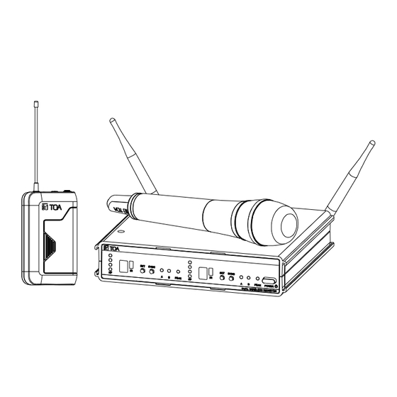
WIRELESS MICROPHONE SYSTEM
CONTENTS
Thank you for purchasing TOA's WS-422/432/402 series Wireless Microphone system.
Please carefully follow the instructions in this manual to ensure long, trouble-free use of your equipment.
OPERATING INSTRUCTIONS
WS-422/432/402 series
8.
9.
Advertisement
Table of Contents

Related Manuals for Toa WS Series


Summary of Contents for Toa WS Series
-
Page 1: Table Of Contents
5. NOMENCLATURE AND FUNCTIONS 6. CHANNEL NUMBER SETTING by MANUAL 7. CHANNEL NUMBER SETTING by INFRARED SYNCHRONIZATION Thank you for purchasing TOA's WS-422/432/402 series Wireless Microphone system. Please carefully follow the instructions in this manual to ensure long, trouble-free use of your equipment. -
Page 2: Safety Precautions
• Should the following irregularity be found during use, immediately switch off the power, disconnect the power supply plug from the AC outlet and contact your nearest TOA dealer. Make no further attempt to operate the unit in this condition as this may cause fire or electric shock. - Page 3 10 days or more. A fire or electric shock may result. • Any modifications made to this device that are not approved by TOA Corporation may void the authority granted to the user to operate this equipment.
-
Page 4: General Description
2. GENERAL DESCRIPTION The TOA’s WS-422/432/402 series W i r e l e s s M i c r o p h o n e s y s t e m is designed for use on the UHF f r e q u e n c y band, and suitable for vocal or speech reinforcement applications. It features a compander circuit which minimizes the influence of ambient noise. -
Page 5: Nomenclature And Functions
5. NOMENCLATURE AND FUNCTIONS Receiver : WT-412 [Front] RECEIVER 1 RECEIVER 2 1. Power switch 6. Infrared (IR) port [IR] Press this switch to turn the power on, and press it Transmit the infrared signal, when pressing again to turn the power off. SYNC key, 2. - Page 6 [Rear] RECEIVER 1 RECEIVER 2 12. AF output 9. Antenna input A, B Balanced XLR jack, male type (Pin #2: Hot). BNC connectors for antennas LINE : 16 dBu / MIC : -20dBu (maximum) Phantom powering external antenna (optional) 13. AF output Unbalanced phone jack For the wireless system covering a...
- Page 7 Handheld microphone : WM-422...
- Page 8 Belt-pack transmitter : WM-432 turn the power off. 1. Power switch Slide this switch towards “ON” to turn the power on, and slide it again towards “OFF” to...
-
Page 9: Channel Number Setting By Manual
2. Power / Battery lamp 7. Battery compartment A green LED lights as long as the battery Insert AA battery accordi ng to (+ ) and (–) capacity is sufficient. When the battery indications on the battery compartment. capacity becomes low, the green LED starts Note: Turn off the power switch. -
Page 10: Channel Number Setting By Infrared Synchronization
7. CHANNEL NUMBER SETTING by INFRARED SYNCHRONIZATION Step 1. Confirm that the receiver is set to the c o rr ec t channel number and the transmitter is turned the power on, then open the battery case on the transmitter. Step 2. -
Page 11: Operational Hints
10. OPERATIONAL HINTS • The transmitter's service distance is 3 – 100 m. When the transmitter user moves in a facility, signal dropouts (momentary losses of signal reception) may be encountered. These dropouts are caused by the building's architectural design or materials which block the travel of or reflect the radio signal. If this occurs, the user needs to change locations for better signal reception. -
Page 12: Specifications
12. SPECIFICATIONS System Modulation Wideband FM UHF band (506-538, 538-576, 576-603, 603-638, 638-671, Frequency Range 671-701, 720-758, 785-815, 819-832, 836-867, 925-937.5 MHz) Tunable Frequencies 25 kHz Steps Switchable Channels Up to 16 channels (depending on region) Operated channels simultaneously Up to 16 channels (depending on region) Pilot tone 32.768kHz Total Harmonic Distortion... - Page 13 FREQUENCY TABLE Frequency Band Code CH Code 925.300 863.150 794.250 803.350 819.150 822.100 748.100 633.475 606.100 616.775 576.150 538.525 506.250 926.550 863.725 794.600 803.975 819.400 822.550 748.600 634.025 606.550 617.725 576.850 539.075 506.575 927.950 864.150 795.050 804.725 820.500 823.400 749.250 634.700 607.600 618.100...
- Page 14 EN 300 422-2 V1.4.1 (2015-06) EN 62368-1:2014 CE Declaration of Conformity 2014/53/EU 2011/65/EU RoHS Traceability Information for Europe Manufacturer: Authorized representative: TOA Corporation TOA Electronics Europe GmbH 7-2-1, Minatojima-Nakamachi, Chuo-ku, Kobe, Suederstrasse 282, 20537 Hamburg, Germany Hyogo, Japan URL: www.toa.de...
- Page 16 URL: http://www.toa.jp/ 133-07-00158-00...
Need help?
Do you have a question about the WS Series and is the answer not in the manual?
Questions and answers