Table of Contents
Advertisement
Available languages
Available languages
Quick Links
Advertisement
Chapters
Table of Contents

Related Manuals for SonoSite SiteStand Mobile Docking Station


Summary of Contents for SonoSite SiteStand Mobile Docking Station
- Page 1 SiteStand Mobile Docking ® Station User Guide...
- Page 2 Non-SonoSite product names may be trademarks or registered trademarks of their respective owners. SonoSite products may be covered by one or more of the following U.S. patents: 4454884, 4462408, 4469106, 4474184, 4475376, 4515017, 4534357, 4542653, 4543960, 4552607, 4561807, 4566035, 4567895, 4581636, 4591355, 4603702, 4607642, 4644795, 4670339, 4773140,...
- Page 3 SiteStand Mobile Docking Station ® User Guide Benutzerhandbuch zur moblien SiteStand -Docking-Station ® Guía del usuario de la unidad complementaria móvil SiteStand ® Guide d’utilisation de la station d’accueil mobile SiteStand ® Manuale dell’utente della stazione mobile di alloggiamento SiteStand ®...
-
Page 5: Table Of Contents
Contents Chapter 1: Overview SiteStand .....................1 SiteStand Displays ..................1 Safety ......................3 Electrical Safety ..................3 Biological Safety .................4 User Safety ..................4 Symbol ....................5 Equipment Protection ...............5 Chapter 2: Using the SiteStand Inserting and Removing the System from the SiteStand ....7 Connecting the SiteStand to AC Power ..........8 Adjusting the Height of the SiteStand ...........9 Locking and Unlocking the Wheels .............10 Replacing the Electrical Fuse ..............11... - Page 6 Chapter 5: Specifications SiteStand ....................31 Physical Dimensions ............... 31 Temperature and Humidity Limits ..........31 Electrical ................... 31 SiteStand Accessories ................32 Peripheral Devices .................. 32 Electromechanical Safety Standards ............ 32 EMC Standards Classification .............. 32...
-
Page 7: Chapter 1: Overview
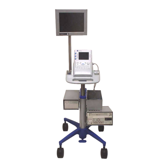
• Provides a mobile, ergonomic work surface with height and angle adjustment • Holds the SonoSite system, two transducers, a printer, a VCR, display, and certain accessories • Charges the system battery and consolidates the following peripheral connections: two video out, an audio out, an RS-232, a printer control, and two AC power •... - Page 8 Display SonoSite system Sleeve Printer bracket and printer Basket VCR bracket and VCR Height adjustment pedal Locking levers Figure 1 SiteStand Mobile Docking Station Chapter 1: Overview...
-
Page 9: Safety
WARNING: recommended by SonoSite on battery power only. Do not connect these products to the AC power connectors on the SiteStand mobile docking station when using the system to scan or diagnose a patient/subject. Contact SonoSite or your local representative for a listing of the commercial grade peripherals available from or recommended by SonoSite. -
Page 10: Biological Safety
Non-medical (commercial) grade peripheral displays have not been verified or WARNING: validated by SonoSite as being suitable for diagnosis. Do not use the system if it exhibits erratic or inconsistent behavior. Discontinuities in the scanning sequence are indicative of a hardware failure that must be corrected before use. -
Page 11: Symbol
Lower stand height and pull over thresholds when transporting. For labeling symbols used with the SiteStand, please refer to the SonoSite Ultrasound System User Guide. For information about the displays, please see the manufacturer’s Operating Instructions shipped with your display. - Page 12 Chapter 1: Overview...
-
Page 13: Chapter 2: Using The Sitestand
Chapter 2: Using the SiteStand This chapter contains information on inserting and removing the system, connecting power, adjusting the height, locking and unlocking the wheels, and replacing the fuse for the SiteStand. Inserting and Removing the System from the SiteStand To insert the system into the SiteStand: Press on the release lever to open the sleeve. -
Page 14: Connecting The Sitestand To Ac Power
To remove the system from the SiteStand: Hold the system by the handle. Press on the release lever to open the sleeve. Carefully remove the system by pulling it up and back. Remove the transducer. Connecting the SiteStand to AC Power To connect the SiteStand to AC power: When AC power is connected to a system installed in the SiteStand, the system battery charges. -
Page 15: Adjusting The Height Of The Sitestand
Adjusting the Height of the SiteStand To lower the SiteStand: Grasp both sides of the sleeve, press down the foot pedal and push down on the sleeve. To raise the SiteStand: Grasp both sides of the sleeve, press down the foot pedal and pull up on the sleeve. -
Page 16: Locking And Unlocking The Wheels
To adjust the angle of the SiteStand: Hold the sleeve. Pull out the knob located under the right side of the sleeve. Adjust the SiteStand to the desired angle (three positions are available); adjust until an audible click is heard. Locking and Unlocking the Wheels The two front wheels (nearest the foot pedal) are lockable. -
Page 17: Replacing The Electrical Fuse
Replacing the Electrical Fuse To replace the electrical fuse: Disconnect the AC line cord from the hospital-grade electrical outlet. Disconnect the AC line cord from the bottom of the SiteStand. Use a small, slotted screwdriver to remove the fuse drawer (located directly below the input AC connector) on the SiteStand. - Page 18 Chapter 2: Using the SiteStand...
-
Page 19: Chapter 3: Using The Accessories
For information about the display, including warnings and cautions, see the manufacturer’s Operating Instructions shipped with the display. When the ultrasound system is in the SiteStand mobile docking station, accessories Caution: or peripherals should be connected to the SiteStand. Connecting them directly to the ultrasound system may cause damage to the equipment. -
Page 20: Sitestand Accessories Configurations
SiteStand Accessories Configurations Display, VCR, and Printer Cables (A) Control (B) Audio–Stand to VCR (C) Composite Video– Stand or Printer to Display Stand to Printer Stand to VCR (D) Video (E) Power Adapter (F) Power Stand to Printer Stand to Printer Stand to VCR Stand to VCR (G) Power–Stand to AC Power... - Page 21 Connecting Display, Printer, and VCR to the SiteStand External Display SiteStand Composite AC In PC Video Video Video Audio RS-232 Video Out Printer Audio Out Remote Video- In AC In Power Out Power Out (insert C here, see note 2) Print/VCR Audio Video...
-
Page 22: Display Only
Display Only Cables (C) Composite Video– (G) Power–Stand to AC Power (wall outlet) Stand or Printer to Display (H) Power–Stand to Display (J) Audio–Stand to Display (12" display only) Connecting the Display to the SiteStand External Display Composite AC In PC Video Audio Video... -
Page 23: Printer Only
Printer Only Cables (A) Control–Stand to Printer (D) Video–Stand to Printer (F) Power–Stand to Printer (G) Power–Stand to AC Power (wall outlet) Connecting the Printer to the SiteStand SiteStand RS-232 Video Out Printer Audio Out Remote Video- In AC In Power Out Power Out Print/VCR... -
Page 24: Troubleshooting Connections
Troubleshooting Connections Symptom Solution External display does not • Check the video format setting in system setup. (See System show an image. User Guide.) • Check the cable connections on display and stand. (See page 15 page 16.) • Check the display to ensure that it is turned on and set up properly (i.e., ready to show correct video format: S-video, composite, or RGB). -
Page 25: Sitestand Display
SiteStand Display The following items are supplied for installing the bracket. Allen wrenches SiteStand VELCRO® bracket strips (3) Screws (2) (part of SiteStand bracket) Clamp (part of SiteStand bracket) Chapter 3: Using the Accessories... -
Page 26: Attaching The Sitestand Display Bracket
(from the front of the SiteStand) on the main support. Note: This step allows clearance for insertion of the SonoSite system into the sleeve from the back of the SiteStand. Tighten the two screws on the bracket clamp. Chapter 3: Using the Accessories... -
Page 27: Attaching The Display To The Sitestand
Attaching the Display to the SiteStand There are two types of mounts, the cylinder-type and the ball-type. Examine the display prior to mounting to determine which type you have. Both types are pictured below. To connect the cylinder-type mount display to the SiteStand: Insert the display onto the top end of the bracket. -
Page 28: Adjusting The Angle Of The Display
To connect the ball-type mount display to the SiteStand: Insert the display onto the top end of the bracket. Caution: To prevent damaging the display, verify that the display is properly seated prior to tightening the knob. Tighten the knob located on the back of the display to secure it to the bracket. - Page 29 To adjust the angle of the cylinder-type display: Hold the display with both hands. Rotate the display forward or back to the desired angle. Note: If at first the display does not rotate, then push more firmly. A set screw controls the tightness of the display angle.
- Page 30 To adjust the angle of the ball-type mount display: Hold the display with both hands. Rotate the angle of the display forward or back to the desired angle. If the display will not adjust, you may need to loosen the knob on the back. To secure the display, tighten the knob.
-
Page 31: Managing Cables
Managing Cables To manage cables: Use the VELCRO strips to secure the power cable and the composite video cable to the bracket. Tilt display back until it is approximately 45 degrees from vertical. Collect all cables together. Wrap composite video cable twice to create loop. Wrap VELCRO strip through loop and around cables, then secure to bracket. -
Page 32: Transporting The Sitestand With A Display
Transporting the SiteStand with a Display To transport the SiteStand with display: To avoid injury to user, patient, or bystander, lower the stand height prior to WARNING: transporting and pull the stand over thresholds. Failure to lower the stand before pulling over thresholds when the display is attached could result in the stand becoming unstable, tipping, or falling over. -
Page 33: Software
SiteLink Image Manager (SiteLink) software is available to use with your system. SiteLink allows you to transfer images from the SonoSite system to a host PC. The transfer is made by using the PC Direct serial cable from the I/O connector and the null-modem serial cable or by using the RS-232 connector on the SiteStand and the null-modem serial cable. - Page 34 Chapter 3: Using the Accessories...
-
Page 35: Chapter 4: Cleaning And Disinfecting Equipment
Chapter 4: Cleaning and Disinfecting Equipment This chapter provides instructions on the proper care of the SiteStand. For information about cleaning and disinfecting the peripheral devices, see the manufacturer’s operating instructions. Cleaning and Disinfecting the SiteStand To avoid electrical shock, remove the system from the SiteStand and unplug from WARNING: AC power before cleaning. -
Page 36: Cleaning And Disinfecting Peripheral Devices
To clean and disinfect the SiteStand: The exterior surface of the SiteStand can be cleaned and disinfected using a recommended cleaner or disinfectant. Remove the system and all contents from the SiteStand. Use a soft cloth lightly dampened in a mild soap or detergent cleaning solution to clean the exterior surfaces of the SiteStand. -
Page 37: Chapter 5: Specifications Sitestand
Refer to the individual operating instructions shipped with each product to determine these limits. Electrical SiteStand mobile docking station input: 100-120/220-240 VAC, 50/60 Hz, 5.2 Amp (Max) SiteStand mobile docking station output: For system: 16 VDC, 2.8 Amp... -
Page 38: Sitestand Accessories
EMC Standards Classification CISPR 11 (1999): Industrial, Scientific, and Medical (ISM) Radio Frequency Equipment Electromagnetic Disturbance Characteristics–Limits and Methods of Measurement. The Classification for the SiteStand, Sonosite system, accessories, and peripherals when configured together is: Group 1, Class A. Chapter 5: Specifications... - Page 39 Benutzerhandbuch zur mobilen SiteStand -Docking-Station ®...
- Page 40 Nicht zu SonoSite gehörende Produktnamen sind u. U. Marken oder eingetragene Marken der jeweiligen Eigentümer. SonoSite Produkte sind u. U. durch eines oder mehrere der folgenden US-Patente geschützt: 4454884, 4462408, 4469106, 4474184, 4475376, 4515017, 4534357, 4542653, 4543960, 4552607, 4561807, 4566035, 4567895, 4581636, 4591355, 4603702, 4607642, 4644795,...
- Page 41 Inhalt Kapitel 1: Übersicht SiteStand .....................1 SiteStand Bildschirme ................1 Sicherheit ....................3 Elektrische Sicherheit ................3 Biologische Sicherheit ...............4 Zu Ihrer Sicherheit ................4 Symbol ....................5 Zum Schutz der Geräte ..............5 Kapitel 2: Verwendung des SiteStand Einsetzen und Entfernen des Systems vom SiteStand ......7 Anschließen des SiteStand an den Netzstrom ........8 Höhenverstellung des SiteStand .............9 Arretieren und Lösen der Räder ............10...
- Page 42 Kapitel 5: Technische Angaben SiteStand ....................31 Abmessungen .................. 31 Grenzwerte für Temperatur und Luftfeuchtigkeit ....31 Elektrische Daten ................31 SiteStand-Zubehör .................. 32 Peripheriegeräte ..................32 Elektromechanische Sicherheitsnormen ..........32 Klassifizierung der EMV-Normen ............32...
-
Page 43: Kapitel 1: Übersicht
Das SiteStand weist folgende Leistungsmerkmale auf: • Mobile, ergonomische Arbeitsfläche mit Höhen- und Neigungsverstellung • Halterungen für das SonoSite System, zwei Schallköpfe, einen Drucker, einen Videorekorder, einen Bildschirm und passendes Zubehör • Lädt den Systemakku auf und fasst die folgenden Peripherieanschlüsse zusammen: zwei Videoausgänge, einen Audioausgang, eine RS-232-Schnittstelle, eine Druckersteuerung und... - Page 44 Bildschirm SonoSite System Schutzkasten Druckerarm und Drucker Korb Videorekorderarm und Videorekorder Höhenverstellungspedal Sperrhebel Abbildung 1 Mobile SiteStand Docking-Station Kapitel 1: Übersicht...
-
Page 45: Sicherheit
Die Geräte nicht an den Netzstromanschluss der mobilen SiteStand Docking-Station anschließen, wenn das System zur Abtastung oder Diagnose eines Patienten eingesetzt wird. Eine Liste der durch SonoSite vertriebenen oder empfohlenen handelsüblichen Peripheriegeräte ist bei SonoSite oder Ihrem örtlichen Kundendienstvertreter erhältlich. -
Page 46: Biologische Sicherheit
In Verbindung mit der biologischen Sicherheit sind die folgenden Vorsichtshinweise zu beachten. Nicht für medizinische Geräte zugelassene (handelsübliche) WARNHINWEIS: Peripheriemonitore wurden durch SonoSite nicht geprüft und nicht für Diagnosezwecke freigegeben. System nicht verwenden, wenn es sprunghaftes oder inkonsistentes Verhalten aufweist. Unstetigkeiten in der Abtastsequenz sind Anzeichen für eine Hardwarestörung, die vor dem Einsatz des Geräts korrigiert werden muss. -
Page 47: Symbol
Verringern Sie daher während des Transports die Stativhöhe, und ziehen Sie das Gerät erst dann über Schwellen. Informationen zur Beschriftung des SiteStand siehe SonoSite Ultraschallsystem-Benutzerhandbuch. Informationen zu den Bildschirmen können Sie den Bedienungsanleitungen der entsprechenden Hersteller entnehmen, die der Lieferung beiliegen. - Page 48 Kapitel 1: Übersicht...
-
Page 49: Kapitel 2: Verwendung Des Sitestand
Kapitel 2: Verwendung des SiteStand Im vorliegenden Kapitel finden Sie Informationen zum Einsetzen und Entfernen des Systems, zum Anschluss an den Netzstrom, zur Höhenverstellung, zum Arretieren und Lösen der Räder sowie zum Auswechseln der Sicherung des SiteStand. Einsetzen und Entfernen des Systems vom SiteStand So wird das System in das SiteStand eingesetzt: Den Schutzkasten durch Drücken des Freigabehebels öffnen. -
Page 50: Anschließen Des Sitestand An Den Netzstrom
So wird das System aus dem SiteStand entfernt: Das System am Griff fassen. Den Schutzkasten durch Drücken des Freigabehebels öffnen. Das System vorsichtig nach oben und hinten herausziehen. Den Schallkopf entfernen. Anschließen des SiteStand an den Netzstrom So wird das SiteStand an den Netzstrom angeschlossen: Während das im SiteStand eingesetzte System an den Netzstrom angeschlossen ist, lädt sich der Akku des Systems auf. -
Page 51: Höhenverstellung Des Sitestand
Höhenverstellung des SiteStand So wird das SiteStand abgesenkt: Den Schutzkasten auf beiden Seiten festhalten, das Fußpedal drücken und den Schutzkasten nach unten drücken. So wird das SiteStand angehoben: Den Schutzkasten auf beiden Seiten festhalten, das Fußpedal drücken und den Schutzkasten nach oben ziehen. -
Page 52: Arretieren Und Lösen Der Räder
So wird die Neigung des SiteStand eingestellt: Den Schutzkasten festhalten. Den unter der rechten Seite des Schutzkastens befindlichen Knopf herausziehen. Das SiteStand im gewünschten Winkel neigen (drei Positionen möglich), bis es mit einem Klicken einrastet. Arretieren und Lösen der Räder Die beiden Vorderräder (direkt am Fußpedal) können arretiert werden. -
Page 53: Auswechseln Der Sicherung
Auswechseln der Sicherung So wird die elektrische Sicherung ersetzt: Das Netzstromkabel von der Wandsteckdose trennen. Das Netzstromkabel von der Buchse unten am SiteStand trennen. Den Sicherungskasten (direkt unterhalb der Netzstromeingangs-Buchse) am SiteStand mit Hilfe eines kleinen Schlitzkopfschraubendrehers entfernen. Ehe das SiteStand wieder an den Netzstrom angeschlossen wird, sollte Vorsichtshinweis: unbedingt die Ursache für die durchgebrannte Sicherung geklärt werden. - Page 54 Kapitel 2: Verwendung des SiteStand...
-
Page 55: Kapitel 3: Verwendung Des Zubehörs
Kapitel 3: Verwendung des Zubehörs Dieses Kapitel erläutert, wie das Zubehör und die Peripheriegeräte am SiteStand angebracht werden. Darüber hinaus werden die SiteLink Bildverwaltungssoftware und die IrfanView Software erläutert. Informationen zum Bildschirm, einschließlich Warn- und Vorsichtshinweisen, können Sie der Bedienungsanleitung des entsprechenden Herstellers entnehmen, die dem Bildschirm beiliegt. Ist das Ultraschallsystem in die mobile SiteStand Docking-Station eingesetzt, Vorsichtshinweis: sollten das Zubehör oder die Peripheriegeräte an das SiteStand... -
Page 56: Konfiguration Des Sitestand Zubehörs
Konfiguration des SiteStand Zubehörs Bildschirm, Videorekorder und Drucker Kabel (A) Steuerung (B) Zwischen Audioanschluss des (C) Videokabel zwischen Stativs und des Stativ bzw. Drucker und Bildschirm Zwischen Stativ und Drucker Videorekorders Zwischen Stativ und Videorekorder (D) Video (E) Netzstromadapter (F) Netzstrom Zwischen Stativ und Drucker Zwischen Stativ und Drucker Zwischen Stativ und Videorekorder... - Page 57 Anschluss des Bildschirms, Druckers und Videorekorders an das SiteStand External Display SiteStand Composite AC In PC Video Video Video Audio RS-232 Video Out Printer Audio Out Remote Video- In AC In Power Out Power Out (insert C here, see note 2) Print/VCR Audio Video...
-
Page 58: Nur Bildschirm
Nur Bildschirm Kabel (C) Videokabel zwischen (G) Netzstromkabel des Stativs (Netzsteckdose) Stativ bzw. Drucker und Bildschirm (H) Stromkabel zwischen Stativ und Bildschirm (J) Audiokabel zwischen Stativ und Bildschirm (nur für 12-Zoll-Bildschirm) Anschluss des Bildschirms am SiteStand External Display Composite AC In PC Video Audio Video... -
Page 59: Nur Drucker
Nur Drucker Kabel (A) Steuerungskabel zwischen Stativ und Drucker (D) Videokabel zwischen Stativ und Drucker (F) Stromkabel zwischen Stativ und Drucker (G) Netzstromkabel des Stands (Netzsteckdose) Anschluss des Druckers am SiteStand SiteStand RS-232 Video Out Printer Audio Out Remote Video- In AC In Power Out Power Out... -
Page 60: Behebung Von Problemen Beim Anschließen
Behebung von Problemen beim Anschließen Problem Lösung Externer Bildschirm zeigt • In der Systemsteuerung das Videoausgabeformat überprüfen. kein Bild an. (Siehe Benutzerhandbuch des Systems). • Kabelverbindungen zwischen Bildschirm und Stativ überprüfen. (Siehe Seite 15 oder Seite 16). • Überprüfen, ob der Bildschirm tatsächlich eingeschaltet und korrekt eingerichtet ist (d. -
Page 61: Sitestand Bildschirm
Problem Lösung Der Drucker funktioniert • Überprüfen, ob in der Systemsteuerung der richtige Drucker nicht. eingestellt ist. (Siehe Benutzerhandbuch des Systems). • Angeschlossene Kabel überprüfen. (Siehe Seite 15 oder Seite 16). • Überprüfen, ob der Drucker tatsächlich eingeschaltet und korrekt eingerichtet ist. (Bei Bedarf finden Sie in der Bedienungsanleitung des Druckerherstellers weitere Hinweise). -
Page 62: Befestigung Des Sitestand Bildschirmarms
Den Arm an der Hauptstütze um 45 Grad nach links drehen (von der Vorderseite des SiteStand aus betrachtet). Hinweis: Hierdurch wird sichergestellt, dass genügend Platz zum Einsetzen des SonoSite Systems bleibt, das von hinten in das SiteStand eingeschoben wird. Beide Schrauben an der Klemmvorrichtung des Arms festziehen. -
Page 63: Befestigung Des Bildschirms Am Sitestand
Befestigung des Bildschirms am SiteStand Es gibt zwei Befestigungstypen – Zylinder- und Kugelbefestigung. Überprüfen Sie vor dem Befestigen, mit welchem Typ Ihr Gerät ausgestattet ist. Beide Typen sind nachfolgend abgebildet. So wird ein Bildschirm mit Zylinderbefestigung am SiteStand befestigt: Den Bildschirm auf das obere Ende des Arms setzen. -
Page 64: Einstellung Der Bildschirmneigung
So wird ein Bildschirm mit Kugelbefestigung am SiteStand befestigt: Den Bildschirm auf das obere Ende des Arms setzen. Vorsichtshinweis: Position und Auflage des Bildschirms vor dem Festdrehen des Knopfes überprüfen, um eine Beschädigung des Bildschirms zu vermeiden. Den Knopf auf der Rückseite des Bildschirms festdrehen, um diesen sicher am Arm zu befestigen. - Page 65 So wird die Neigung bei Bildschirmen mit Zylinderbefestigung eingestellt: Den Bildschirm mit beiden Händen festhalten. Den Bildschirm wie gewünscht nach vorne oder hinten neigen. Hinweis: Etwas fester drücken, wenn sich der Bildschirm zunächst nicht drehen lässt. Der Neigungswinkel des Bildschirms wird über eine Stellschraube eingestellt.
- Page 66 So wird die Neigung bei Bildschirmen mit Kugelbefestigung eingestellt: Den Bildschirm mit beiden Händen festhalten. Den Bildschirm nach vorne oder hinten drehen, bis die gewünschte Neigung erreicht ist. Wenn sich der Bildschirm nicht einstellen lässt, muss möglicherweise der Knopf auf der Rückseite etwas gelockert werden.
-
Page 67: Ordentliche Fixierung Von Kabeln
Ordentliche Fixierung von Kabeln So fixieren Sie die Kabel ordentlich: Das Netzkabel und das Videokabel mithilfe der Klettverschlüsse am SiteStand-Arm befestigen. Den Bildschirm zurückkippen, bis er ungefähr einen Winkel von 45 Grad von der vertikalen Stellung hat. Alle Kabel bündeln. Das Videokabel zu einer Schlaufe legen. -
Page 68: Transport Des Sitestand Mit Bildschirm
Transport des SiteStand mit Bildschirm Beim Transport des SiteStand mit Bildschirm ist Folgendes zu beachten: Um Bediener, Patienten oder Anwesende vor Verletzungen zu schützen, WARNHINWEIS: verringern Sie vor dem Transport die Stativhöhe. Ziehen Sie erst dann das Stativ über Schwellen. Wird die Stativhöhe nicht verringert und das Stativ über eine Schwelle geschoben, besteht bei angebrachtem Bildschirm die Gefahr, dass das Stativ instabil wird, kippt oder umfällt. -
Page 69: Software
Nullmodemkabel statt. Weitere Informationen sind dem Benutzerhandbuch für den SiteLink Bildverwalter zu entnehmen, das im PDF-Format auf der SiteLink CD-ROM zur Verfügung steht. Hinweis: Die Verbindungsfunktion über das serielle PC-Kabel ist deaktiviert, wenn das SonoSite-System in der SiteStand Docking-Station installiert ist. - Page 70 Kapitel 3: Verwendung des Zubehörs...
-
Page 71: Kapitel 4: Reinigung Und Desinfektion Der Geräte
Kapitel 4: Reinigung und Desinfektion der Geräte In diesem Kapitel wird beschrieben, wie das SiteStand ordnungsgemäß gepflegt wird. Informationen zur Reinigung und Desinfektion der Peripheriegeräte sind den Bedienungsanweisungen des Herstellers zu entnehmen. Reinigung und Desinfektion des SiteStand Um einen elektrischen Schlag zu vermeiden, das System vor dem Reinigen WARNHINWEIS: aus dem SiteStand nehmen und den Stecker ziehen. -
Page 72: Reinigung Und Desinfektion Der Peripheriegeräte
Reinigung und Desinfektion des SiteStand: Die Außenflächen des SiteStand können mit Hilfe eines empfohlenen Reinigungs- oder Desinfektionsmittels gereinigt oder desinfiziert werden. Das System und den gesamten Inhalt aus dem SiteStand nehmen. Die Außenflächen des SiteStand mit einem weichen, leicht mit einer milden Seifen- oder Detergenslösung angefeuchteten Tuch reinigen. -
Page 73: Kapitel 5: Technische Angaben
Kapitel 5: Technische Angaben SiteStand Abmessungen Höhe: 115,2 cm Breite: 52,3 cm Tiefe: 60,8 cm Gewicht: 23,1 kg Grenzwerte für Temperatur und Luftfeuchtigkeit Lagerung und Transport Max.: 65 °C, 95 % relative Luftfeuchtigkeit, nicht kondensierend Min.: -35 °C, 15 % relative Luftfeuchtigkeit, nicht kondensierend Betriebsumgebung Max.: 40 °C, 95 % relative Luftfeuchtigkeit, nicht kondensierend Min.: 10 °C, 15 % relative Luftfeuchtigkeit, nicht kondensierend... -
Page 74: Sitestand-Zubehör
Electromagnetic Disturbance Characteristics – Limits and Methods of Measurement (Grenzwerte und Messverfahren der Funkstörcharakteristiken von industriellen, wissenschaftlichen und medizinischen Hochfrequenzanlagen). Sind SiteStand, Sonosite System, Zubehör und Peripheriegeräte zusammen konfiguriert, ist die Klassifizierung wie folgt: Gruppe 1, Klasse A. Kapitel 5: Technische Angaben... - Page 75 Guía del usuario de la unidad complementaria móvil SiteStand ®...
- Page 76 Los nombres de productos ajenos a SonoSite pueden ser marcas comerciales o registradas de sus respectivos propietarios. Los productos SonoSite pueden estar amparados por una o más de las siguientes patentes de los Estados Unidos: 4454884, 4462408, 4469106, 4474184, 4475376, 4515017, 4534357, 4542653, 4543960, 4552607, 4561807, 4566035, 4567895, 4581636, 4591355, 4603702,...
- Page 77 Contenido Capítulo 1: Descripción general SiteStand .....................1 Pantallas del SiteStand ................1 Seguridad ....................3 Seguridad eléctrica ................3 Seguridad biológica ................4 Seguridad del usuario ...............4 Símbolo ....................5 Protección del equipo ................5 Capítulo 2: Utilización de SiteStand Inserción y extracción del sistema en el SiteStand .......7 Conexión del SiteStand a la alimentación de CA .........8 Ajuste de la altura del SiteStand .............9 Bloqueo y desbloqueo de las ruedas ............10...
- Page 78 Capítulo 5: Especificaciones SiteStand ....................31 Dimensiones físicas ................. 31 Límites de humedad y temperatura ..........31 Electricidad ..................31 Accesorios para SiteStand ..............32 Dispositivos periféricos ................. 32 Normativas de seguridad electromecánica ........32 Clasificación estándar EMC ..............32...
-
Page 79: Capítulo 1: Descripción General
• Proporciona una superficie de trabajo ergonómica, móvil, con ajuste del ángulo y de la altura • Sostiene al sistema SonoSite, dos transductores, una impresora, una videocasetera, una pantalla y algunos accesorios • Carga la batería del sistema y consolida las conexiones de periféricos siguientes: dos puertos de salida de vídeo, un puerto de salida de audio, un puerto RS-232, un puerto para control de... - Page 80 Pantalla Sistema SonoSite Estuche Soporte de la impresora e impresora Cesta Soporte de la videocasetera y videocasetera Pedal de ajuste de la altura Palancas de bloqueo Figura 1 Unidad complementaria móvil SiteStand Capítulo 1: Descripción general...
-
Page 81: Seguridad
CA de la unidad complementaria móvil SiteStand cuando utilice el sistema para la exploración o diagnóstico de pacientes. Póngase en contacto con SonoSite o con el representante local para obtener una lista de los periféricos de calidad comercial disponibles o recomendados por SonoSite. -
Page 82: Seguridad Biológica
Seguridad biológica Observe las siguientes precauciones relacionadas con la seguridad biológica. SonoSite no ha verificado ni validado como adecuados para diagnóstico los ADVERTENCIA: monitores periféricos de calidad (comercial) no médica. No utilice el sistema si muestra un comportamiento errático o incoherente. -
Page 83: Símbolo
Para obtener más información sobre los símbolos del etiquetado del SiteStand, consulte el Manual para el usuario del sistema de ecografía SonoSite. Para obtener más información acerca de las pantallas, consulte las instrucciones de uso del fabricante que se entregan con la pantalla. - Page 84 Capítulo 1: Descripción general...
-
Page 85: Capítulo 2: Utilización De Sitestand
Capítulo 2: Utilización de SiteStand Este capítulo indica la manera de insertar y retirar el equipo, conectar la alimentación, ajustar la altura, bloquear y desbloquear las ruedas y sustituir el fusible del SiteStand. Inserción y extracción del sistema en el SiteStand Para insertar el sistema en el SiteStand Presione la palanca de desbloqueo para abrir el estuche. -
Page 86: Conexión Del Sitestand A La Alimentación De Ca
Para retirar el sistema del SiteStand: Sujete el sistema por el mango. Presione la palanca de desbloqueo para abrir el estuche. Retire con cuidado el sistema tirando de él hacia arriba y hacia atrás. Retire el transductor. Conexión del SiteStand a la alimentación de CA Para conectar el SiteStand a la alimentación de CA: Cuando se conecta la alimentación de CA a un sistema instalado en el SiteStand, el sistema carga las baterías. -
Page 87: Ajuste De La Altura Del Sitestand
Ajuste de la altura del SiteStand Para bajar el SiteStand: Sujetando ambos lados del estuche, pulse el pedal y presione hacia abajo en el estuche. Para elevar el SiteStand: Sujetando ambos lados del estuche, pulse el pedal y tire hacia arriba del estuche. Nota: El sistema se debe ajustar a la altura adecuada antes de utilizarlo. -
Page 88: Bloqueo Y Desbloqueo De Las Ruedas
Para ajustar la altura del SiteStand: Sujete el estuche. Tire hacia afuera del botón situado bajo el lado derecho del estuche. Ajuste el SiteStand al ángulo deseado (están disponibles tres posiciones); ajústelo hasta que se escuche un clic. Bloqueo y desbloqueo de las ruedas Se pueden bloquear las dos ruedas anteriores (las más próximas al pedal). -
Page 89: Sustitución Del Fusible Eléctrico
Sustitución del fusible eléctrico Para sustituir el fusible eléctrico: Desconecte el cable de alimentación de CA de la toma eléctrica para aplicaciones hospitalarias. Desconecte el cable de alimentación de CA de la parte inferior del SiteStand. Utilice un destornillador pequeño, ranurado, para retirar el portafusibles (que se encuentra directamente por debajo de la toma de entrada de CA) del SiteStand. - Page 90 Capítulo 2: Utilización de SiteStand...
-
Page 91: Capítulo 3: Utilización De Los Accesorios
Capítulo 3: Utilización de los accesorios Este capítulo proporciona instrucciones acerca de la instalación de los accesorios y periféricos en la unidad SiteStand. También se describen el Administrador de imágenes SiteLink y el software IrfanView. Para obtener información acerca de la pantalla, incluidas las precauciones y llamadas de atención, vea las instrucciones de funcionamiento entregadas con la pantalla. -
Page 92: Configuración De Los Accesorios Del Sitestand
Configuración de los accesorios del SiteStand Pantalla, videocasetera e impresora Cables (A) Control (B) Audio: del soporte a la (C) Cable mixto de vídeo: videocasetera del soporte o la impresora a la Del soporte a la impresora pantalla Del soporte a la videocasetera (D) Vídeo (E) Adaptador de corriente (F) Alimentación... - Page 93 Conexión de la pantalla, la impresora y la videocasetera al SiteStand External Display SiteStand Composite AC In PC Video Video Video Audio RS-232 Video Out Printer Audio Out Remote Video- In AC In Power Out Power Out (insert C here, see note 2) Print/VCR Audio...
-
Page 94: Solamente De La Pantalla
Solamente de la pantalla Cables (C) Cable mixto de vídeo: (G) Alimentación: del soporte a la alimentación de CA del soporte o la impresora a la pantalla (toma mural) (H) Alimentación: del soporte a la pantalla (J) Audio: del soporte a la pantalla (sólo pantallas de 12”) Conexión de la pantalla al SiteStand External Display Composite... -
Page 95: Solamente De La Impresora
Solamente de la impresora Cables (A) Control: del soporte a la impresora (D) Vídeo: del soporte a la impresora (F) Alimentación: del soporte a la impresora (G) Alimentación: del soporte a la alimentación de CA (toma mural) Conexión de una impresora al SiteStand SiteStand RS-232 Video Out... -
Page 96: Solución De Problemas Con Las Conexiones
Solución de problemas con las conexiones Síntoma Solución La pantalla externa no • Compruebe el formato de vídeo en la configuración del muestra ninguna imagen. sistema. (Vea la guía del usuario del sistema.) • Compruebe las conexiones de cable en la pantalla y en el soporte. -
Page 97: Pantalla Del Sitestand
Síntoma Solución La impresora no funciona. • Compruebe que se haya seleccionado la impresora en la configuración del sistema. (Vea la guía del usuario del sistema.) • Compruebe las conexiones de cable. (Consulte la página 15 o la página 16.) •... -
Page 98: Fijación Del Soporte De Pantalla Del Sitestand
Gire el soporte unos 45 grados hacia la izquierda (desde la parte frontal del SiteStand) en el soporte principal. Nota: Este paso permite cierta separación para insertar el sistema SonoSite en el estuche desde la parte trasera del SiteStand. Apriete los dos tornillos en la abrazadera del soporte. -
Page 99: Sujeción De La Pantalla Al Sitestand
Sujeción de la pantalla al SiteStand Existen dos tipos de monturas: la de cilindro y la de bola. Examine la pantalla antes de su montaje para determinar qué tipo tiene. Ambos tipos se muestran a continuación. Para conectar la pantalla de montaje tipo cilíndrico al SiteStand: Inserte la pantalla en el extremo superior del soporte. -
Page 100: Ajuste Del Ángulo De La Pantalla
Para conectar la pantalla con montura de tipo bola al SiteStand: Inserte la pantalla en el extremo superior del soporte. Atención: Para evitar que se dañe la pantalla, compruebe que esté bien asentada antes de apretar el botón. Apriete el botón situado en la parte trasera de la pantalla para asegurarla al soporte. - Page 101 Para ajustar el ángulo de la pantalla de tipo cilindríco: Sujete la pantalla con ambas manos. Gire la pantalla hacia adelante o hacia atrás hasta lograr el ángulo deseado. Nota: Si al principio la pantalla no gira, aplique más fuerza. El tornillo de ajuste controla el apriete del ángulo de pantalla (vea la flecha).
- Page 102 Para ajustar el ángulo de la pantalla tipo bola: Sujete la pantalla con ambas manos. Gire el ángulo de la pantalla hacia adelante o hacia atrás, hasta lograr el ángulo deseado. Si no se ajusta la pantalla, puede que tenga que aflojar el botón situado en la parte trasera.
-
Page 103: Organización De Los Cables
Organización de los cables Para organizar los cables: Utilice tiras de VELCRO para asegurar el cable de la fuente de alimentación y el cable mixto de vídeo al soporte. Incline la pantalla hacia atrás hasta que se encuentre a 45 grados desde la posición vertical. Junte todos los cables. -
Page 104: Transporte Del Sitestand Con Una Pantalla
Transporte del SiteStand con una pantalla Para transportar el SiteStand con la pantalla: Para evitar lesiones al usuario, al paciente o a la persona que esté al lado, baje ADVERTENCIA: la altura del soporte antes de transportarlo y tire de él al subir escalones. Si no baja el soporte antes de subir escalones cuando está... -
Page 105: Software
Administrador de imágenes SiteLink, disponible en formato PDF en el CD-ROM de SiteLink. Nota: La función de conexión PC Direct no funcionará cuando el sistema SonoSite se instale en el SiteStand. El personal sanitario que dispone o transmite información de esta índole debe Atención:... - Page 106 Capítulo 3: Utilización de los accesorios...
-
Page 107: Capítulo 4: Limpieza Y Desinfección Del Equipo
Capítulo 4: Limpieza y desinfección del equipo Este capítulo proporciona instrucciones sobre el cuidado adecuado del SiteStand. Para obtener más información acerca de la limpieza y desinfección de los dispositivos periféricos, véase las instrucciones de uso del fabricante. Limpieza y desinfección del SiteStand Para evitar una descarga eléctrica, antes de realizar la limpieza, retire el ADVERTENCIA: sistema del SiteStand y desenchúfelo de la alimentación de CA. -
Page 108: Limpieza Y Desinfección De Dispositivos Periféricos
Para limpiar y desinfectar el SiteStand: La superficie exterior del SiteStand puede limpiarse y desinfectarse utilizando una solución de limpieza o un desinfectante recomendados. Retire el sistema y todo el contenido del SiteStand. Para limpiar las superficies exteriores del SiteStand, utilice un paño suave ligeramente humedecido con una solución de limpieza jabonosa o de detergente suaves. -
Page 109: Capítulo 5: Especificaciones
Capítulo 5: Especificaciones SiteStand Dimensiones físicas Altura: 115,2 cm Anchura: 52,3 cm Profundidad: 60,8 cm Peso: 23,1 kg Límites de humedad y temperatura Almacenamiento y envío Superior: 65 ºC, 95% de humedad relativa sin condensación Inferior: -35 ºC, 15% de humedad relativa sin condensación Entorno de trabajo Superior: 40 ºC, 95% de humedad relativa sin condensación Inferior: 10 ºC, 15% de humedad relativa sin condensación... -
Page 110: Accesorios Para Sitestand
CISPR 11 (1999): Características de perturbaciones electromagnéticas en equipos de radiofrecuencia industriales, científicos y médicos (ISM) – Límites y métodos de medición. La clasificación del sistema SonoSite, el SiteStand y sus accesorios y periféricos cuando se configuran juntos es: Grupo 1, Clase A. - Page 111 Guide d’utilisation de la station d’accueil mobile SiteStand ®...
- Page 112 Attention : demande. « iLook », « SiteCharge », « SitePack », « SiteStand » et « SonoHeart », sont des marques de SonoSite, Inc. VELCRO est une marque déposée de Velcro Industries B.V. Les noms de produits non fabriqués par SonoSite peuvent être des marques ou des marques déposées de leurs propriétaires respectifs.
- Page 113 Table des matières Chapitre 1 : Présentation SiteStand .....................1 Écrans de SiteStand ...................1 Sécurité .......................3 Sécurité électrique ................3 Sécurité biologique ................4 Sécurité de l’utilisateur ..............4 Symbole ....................5 Protection du matériel ..............5 Chapitre 2 : Utilisation de SiteStand Insertion et retrait de l’échographe de la station d’accueil SiteStand ..................7 Branchement de la station SiteStand sur l’alimentation secteur ..8 Réglage de la hauteur de la station SiteStand ........9...
- Page 114 Chapitre 5 : Caractéristiques techniques SiteStand ....................31 Dimensions physiques ..............31 Limites de température et d’humidité ......... 31 Alimentation électrique ..............31 Accessoires de la station SiteStand ............32 Les périphériques ................... 32 Normes de sécurité électromécanique ..........32 Classification des normes de CEM ............
-
Page 115: Chapitre 1 : Présentation
• fournit une surface ergonomique mobile de hauteur et inclinaison réglables • sert de support pour l’échographe SonoSite, deux sondes, une imprimante, un magnétoscope, un écran et certains accessoires • charge la batterie de l’échographe et réunit les branchements de périphériques suivants : deux ports de sortie vidéo, un port de sortie audio, un port de communication RS-232C, un port de... - Page 116 Écran Échographe SonoSite Manchon Support d’imprimante et imprimante Panier Support de magnétoscope et magnétoscope Pédale de réglage de hauteur Leviers de blocage Figure 1 Station d’accueil mobile SiteStand Chapitre 1 : Présentation...
-
Page 117: Sécurité
Ne pas brancher ces produits sur les prises d’alimentation secteur de la station d’accueil mobile SiteStand lorsque l’échographe est utilisé pour l’échographie ou le diagnostic d’un patient/sujet. Contacter SonoSite ou le représentant le plus proche pour obtenir la liste des périphériques de qualité... -
Page 118: Sécurité Biologique
Les écrans de qualité non médicale (commerciaux) n’ont pas été vérifiés ni AVERTISSEMENT : validés par SonoSite pour une utilisation diagnostique. Ne pas utiliser l’échographe s’il se comporte de manière peu fiable ou capricieuse. Toute discontinuité dans la séquence de balayage indique une défaillance matérielle à... -
Page 119: Symbole
Pour déplacer la station, abaisser sa hauteur et passer les seuils en marche arrière. Pour plus de détails concernant les symboles d’étiquetage utilisés pour SiteStand, se reporter au Guide d’utilisation de l’échographe SonoSite. Pour des informations sur les écrans, se reporter au manuel fourni avec l’écran. Protection du matériel Afin de protéger l’échographe, les accessoires et les périphériques, prendre la précaution suivante. - Page 120 Chapitre 1 : Présentation...
-
Page 121: Chapitre 2 : Utilisation De Sitestand
Chapitre 2 : Utilisation de SiteStand Ce chapitre contient des informations sur l’insertion et le retrait de l’échographe, les branchements électriques, le réglage de la hauteur, le blocage et le déblocage des roues, ainsi que le remplacement du fusible du SiteStand. Insertion et retrait de l’échographe de la station d’accueil SiteStand Pour insérer l’échographe dans la station SiteStand... -
Page 122: Branchement De La Station Sitestand Sur L'alimentation Secteur
Pour retirer l’échographe de la station SiteStand : Saisir l’échographe par sa poignée. Appuyer sur le levier de déverrouillage pour ouvrir le manchon. Retirer l’échographe avec précaution en le soulevant tout en le tirant vers l’arrière. Retirer la sonde. Branchement de la station SiteStand sur l’alimentation secteur Pour brancher la station SiteStand sur l’alimentation secteur : Lorsque l’alimentation secteur est branchée sur un échographe installé... -
Page 123: Réglage De La Hauteur De La Station Sitestand
Réglage de la hauteur de la station SiteStand Pour abaisser la station SiteStand : Maintenir le manchon à deux mains, appuyer sur la pédale et sur le manchon. Pour rehausser la station SiteStand : Maintenir le manchon à deux mains, appuyer sur la pédale et tirer sur le manchon. -
Page 124: Blocage Et Déblocage Des Roues
Pour régler l’inclinaison de la station SiteStand : Tenir le manchon. Tirer sur le bouton situé sous le côté droit du manchon. Régler l’inclinaison de la station SiteStand (trois positions possibles) ; régler jusqu’à ce qu’un déclic se fasse entendre. Blocage et déblocage des roues Les deux roues avant (les plus proches de la pédale) peuvent être bloquées. -
Page 125: Remplacement Du Fusible
Remplacement du fusible Pour remplacer le fusible : Débrancher le cordon d’alimentation secteur de la prise électrique de qualité hôpital. Débrancher le cordon d’alimentation secteur de la base de SiteStand. Utiliser un petit tournevis pour écrous à fente pour retirer le tiroir à fusible (situé juste en dessous de la prise d’alimentation secteur) de SiteStand. - Page 126 Chapitre 2 : Utilisation de SiteStand...
-
Page 127: Chapitre 3 : Utilisation Des Accessoires
Chapitre 3 : Utilisation des accessoires Ce chapitre présente les instructions d’installation des accessoires et des périphériques avec la station SiteStand. Le Logiciel de gestion d’images SiteLink et le logiciel IrfanView sont également décrits. Pour des informations sur l’écran, y compris les avertissements et précautions, se reporter au manuel fourni avec l’écran. -
Page 128: Configurations Des Accessoires De La Station Sitestand
Configurations des accessoires de la station SiteStand Écran, magnétoscope et imprimante Câbles (A) Commande (B) Audio : Station - (C) Vidéo composite : Magnétoscope Station ou Imprimante - Écran Station - Imprimante Station - Magnétoscope (D) Vidéo (E) Adaptateur secteur (F) Alimentation Station - Imprimante Station - Imprimante... - Page 129 Connexion de l’écran, de l’imprimante et du magnétoscope à la station SiteStand External Display SiteStand Composite AC In PC Video Video Video Audio RS-232 Video Out Printer Audio Out Remote Video- In AC In Power Out Power Out (insert C here, see note 2) Print/VCR Audio...
-
Page 130: Écran Uniquement
Écran uniquement Câbles (C) Vidéo composite : (G) Alimentation : Station - Alimentation secteur (prise Station ou Imprimante - Écran murale) (H) Alimentation : Station - Écran (J) Audio : Station - Écran (écran 30,5 cm uniquement) Connexion de l’écran à la station SiteStand External Display Composite AC In... -
Page 131: Imprimante Uniquement
Imprimante uniquement Câbles (A) Commande : Station - Imprimante (D) Vidéo : Station - Imprimante (F) Alimentation : Station - Imprimante (G) Alimentation : Station - Alimentation secteur (prise murale) Connexion de l’imprimante à la station SiteStand SiteStand RS-232 Video Out Printer Audio Out Remote... -
Page 132: Problèmes Liés Aux Connexions
Problèmes liés aux connexions Symptôme Solution L’écran externe n’affiche • Vérifier le réglage du format vidéo dans la configuration du pas d’image. système. (Se reporter au guide d’utilisation.) • Vérifier les connexions sur l’écran et la station. (Se reporter à page 15 à... -
Page 133: Écran De Sitestand
Écran de SiteStand Les éléments suivants sont fournis pour l’installation du support. Clés Allen Support Bandes SiteStand VELCRO® (3) Vis (2) (partie du support SiteStand) Collier de serrage (partie du support SiteStand) Chapitre 3 : Utilisation des accessoires... -
Page 134: Fixation Du Support D'écran Sitestand
(depuis le devant du SiteStand) sur le support principal. Remarque : Cette étape permet de libérer l’espace nécessaire à l’insertion de l’échographe SonoSite dans le manchon depuis l’arrière de la station SiteStand. Serrer les deux vis sur le collier de serrage du support. -
Page 135: Fixation De L'écran À La Station Sitestand
Fixation de l’écran à la station SiteStand Il existe deux types de systèmes de fixation : de type cylindre et de type bille. Avant la fixation, observer l’écran afin de déterminer son type. Les deux types sont représentés ci-dessous. Pour brancher un écran à fixation de type cylindre sur la station SiteStand : Insérer l’écran par l’extrémité... -
Page 136: Réglage De L'angle D'inclinaison De L'écran
Pour brancher un écran à fixation de type bille sur la station SiteStand : Insérer l’écran par l’extrémité supérieure du support. Attention : Pour éviter d’endommager l’écran, s’assurer qu’il est bien mis en place avant de serrer le bouton. Serrer le bouton situé à l’arrière de l’écran pour le fixer sur le support. - Page 137 Pour régler l’angle d’inclinaison d’un écran de type cylindre : Saisir l’écran des deux mains. Faire pivoter l’écran vers l’avant ou vers l’arrière selon l’angle désiré. Remarque : S’il ne pivote pas, exercer une pression plus importante. Une vis de fixation permet d’ajuster précisément l’angle d’inclinaison de l’écran.
- Page 138 Pour régler l’angle d’inclinaison d’un écran de type bille : Saisir l’écran des deux mains. Incliner l’écran vers l’avant ou vers l’arrière, selon l’angle souhaité. Si vous ne parvenez pas à le régler, desserrer le bouton situé à l’arrière. Pour fixer l’écran dans la position désirée, resserrer le bouton.
-
Page 139: Gestion Des Câbles
Gestion des câbles Pour gérer les câbles : Utiliser les trois bandes VELCRO pour fixer le câble d’alimentation et le câble vidéo composite sur le support. Faire basculer le moniteur vers l’arrière jusqu’à ce soit à 45 degrés de la verticale. Rassembler tous les câbles. -
Page 140: Transport De La Station Sitestand Équipée D'un Écran
Transport de la station SiteStand équipée d’un écran Pour transporter la station SiteStand équipée d’un écran : Pour éviter que l’utilisateur, le patient ou un tiers ne se blesse, abaisser la AVERTISSEMENT : station avant de la déplacer et passer les seuils en marche arrière. Lorsque la station est équipée de l’écran, tout manquement au respect des recommandations indiquées ci-dessus, risque d’entraîner le déséquilibre, le basculement ou la chute de la station. -
Page 141: Logiciel
Le Logiciel de gestion d’images SiteLink (SiteLink) est compatible avec votre système. Le logiciel SiteLink permet le transfert d’images de l’échographe SonoSite vers un PC hôte. Le transfert s’effectue soit via le câble série direct PC du connecteur I/O et le câble série de simulateur de modem ou via la prise RS-232C du SiteStand et le câble série simulateur de modem. - Page 142 Chapitre 3 : Utilisation des accessoires...
-
Page 143: Chapitre 4 : Nettoyage Et Désinfection Du Matériel
Chapitre 4 : Nettoyage et désinfection du matériel Ce chapitre fournit des informations sur l’entretien de la station SiteStand. Pour les consignes de nettoyage et de désinfection des périphériques, consulter leurs notices d’utilisation respectives. Nettoyage et désinfection de la station SiteStand Avant le nettoyage, retirer l’échographe de la station SiteStand et le AVERTISSEMENT : débrancher du secteur pour éviter tout risque d’électrocution. -
Page 144: Nettoyage Et Désinfection Des Périphériques
Pour nettoyer et désinfecter SiteStand : La surface externe de SiteStand peut être nettoyée et désinfectée à l’aide d’un produit nettoyant ou désinfectant recommandé. Retirer l’appareil et tout contenu de la station SiteStand. Pour nettoyer les surfaces externes de SiteStand, utiliser un linge doux imbibé d’une solution nettoyante savonneuse ou de détergent peu agressif. -
Page 145: Chapitre 5 : Caractéristiques Techniques
Chapitre 5 : Caractéristiques techniques SiteStand Dimensions physiques Hauteur : 115,2 cm Largeur : 52,3 cm Profondeur : 60,8 cm Poids : 23,1 kg Limites de température et d’humidité Entreposage et transport Haute : 65 ºC, humidité relative de 95 % sans condensation Basse : -35 ºC, humidité... -
Page 146: Accessoires De La Station Sitestand
CISPR 11 (1999): Caractéristiques des perturbations radiofréquence industrielles, scientifiques et médicales (ISM) - Limites et méthodes de mesure. La classification de l’ensemble comprenant la station SiteStand, l’échographe Sonosite, les accessoires et les périphériques est la suivante : Groupe 1, Classe A. - Page 147 Manuale dell’utente della stazione mobile di alloggiamento SiteStand ®...
- Page 148 I nomi dei prodotti non SonoSite possono essere marchi o marchi registrati dei rispettivi proprietari. I prodotti SonoSite possono essere tutelati da uno o più dei seguenti brevetti U.S.A.: 4454884, 4462408, 4469106, 4474184, 4475376, 4515017, 4534357, 4542653, 4543960, 4552607, 4561807, 4566035, 4567895, 4581636, 4591355, 4603702, 4607642, 4644795, 4670339,...
- Page 149 Sommario Capitolo 1: Cenni generali SiteStand .....................1 Display SiteStand ..................1 Sicurezza .....................3 Sicurezza elettrica ................3 Sicurezza biologica ................4 Sicurezza dell’utente .................4 Simbolo ....................5 Protezione dei dispositivi ..............5 Capitolo 2: Utilizzo di SiteStand Inserimento e rimozione del sistema da SiteStand ......7 Collegamento di SiteStand alla rete di alimentazione a corrente alternata ..................8 Regolazione dell’altezza di SiteStand ............9...
- Page 150 Capitolo 5: Caratteristiche tecniche SiteStand ....................31 Dimensioni fisiche ................31 Limiti di temperatura e umidità ........... 31 Caratteristiche elettriche ..............31 Accessori SiteStand ................32 Periferiche ....................32 Standard di sicurezza elettromeccanica ..........32 Standard per le apparecchiature ECG ..........32...
-
Page 151: Capitolo 1: Cenni Generali
• alloggiare il sistema SonoSite, due trasduttori, una stampante, un videoregistratore, il display e alcuni accessori; • caricare la batteria del sistema e utilizzare i seguenti collegamenti delle periferiche: due uscite video, un’uscita audio, un connettore RS-232, un connettore per il controllo stampante e due... - Page 152 Display Sistema SonoSite Alloggiamento Stampante e staffa per stampante Cestino Videoregistratore e staffa per videoregistratore Pedale per la regolazione dell’altezza Levette di blocco Figura 1 Stazione mobile di alloggiamento SiteStand Capitolo 1: Cenni generali...
-
Page 153: Sicurezza
SonoSite. Il collegamento di accessori e periferiche non espressamente consigliati da SonoSite potrebbe causare scosse elettriche. Per un elenco di accessori e periferiche forniti o consigliati da SonoSite, rivolgersi a SonoSite o al rappresentante più vicino. Le scariche di elettricità statica costituiscono un fenomeno naturale e frequente. -
Page 154: Sicurezza Biologica
I display di tipo non medicale (commerciale) non sono stati verificati né AVVERTENZA: approvati da SonoSite come idonei alla diagnosi. Non usare il sistema in caso di funzionamento irregolare o discontinuo. Eventuali irregolarità nella sequenza di scansione indicano un errore dell’hardware, che va corretto prima di utilizzare il sistema. -
Page 155: Simbolo
Per i simboli delle etichette utilizzati con SiteStand, fare riferimento al Manuale dell’utente del sistema per ecografia SonoSite. Per informazioni sui display, fare riferimento alle istruzioni operative fornite dal produttore del display. Protezione dei dispositivi Per la protezione del sistema per ecografia, degli accessori e delle periferiche, seguire le precauzioni riportate di seguito. - Page 156 Capitolo 1: Cenni generali...
-
Page 157: Capitolo 2: Utilizzo Di Sitestand
Capitolo 2: Utilizzo di SiteStand In questo capitolo viene illustrato come inserire ed estrarre il sistema, collegare l’alimentazione, regolare l’altezza, bloccare e sbloccare le rotelle e sostituire il fusibile nel sistema SiteStand. Inserimento e rimozione del sistema da SiteStand Per inserire il sistema in SiteStand Premere sulla leva di sblocco per aprire l’alloggiamento. -
Page 158: Collegamento Di Sitestand Alla Rete Di Alimentazione A
Per rimuovere il sistema da SiteStand: Tenere il sistema per la maniglia. Premere sulla leva di sblocco per aprire l’alloggiamento. Rimuovere con attenzione il sistema sollevandolo e tirandolo indietro. Rimuovere il trasduttore. Collegamento di SiteStand alla rete di alimentazione a corrente alternata Procedura per il collegamento di SiteStand alla rete di alimentazione a corrente alternata... -
Page 159: Regolazione Dell'altezza Di Sitestand
Regolazione dell’altezza di SiteStand Per abbassare SiteStand: Afferrare l’alloggiamento su entrambi i lati, premere il pedale e spingere verso il basso. Per alzare SiteStand: Afferrare l’alloggiamento su entrambi i lati, premere il pedale e tirare verso l’alto. Nota: Prima di utilizzare il sistema, regolare l’altezza in modo appropriato. -
Page 160: Blocco E Sblocco Delle Rotelle
Per regolare l’angolazione di SiteStand: Mantenere l’alloggiamento. Tirare verso l’esterno la manopola situata sotto il lato destro dell’alloggiamento. Regolare SiteStand in base all’angolazione desiderata (sono disponibili tre posizioni); procedere con la regolazione finché non si sente un "clic". Blocco e sblocco delle rotelle È... -
Page 161: Sostituzione Del Fusibile
Sostituzione del fusibile Per sostituire il fusibile: Scollegare il cavo di linea a corrente alternata dalla presa di corrente per uso ospedaliero. Scollegare il cavo di linea a corrente alternata dalla base di SiteStand. Servendosi di un piccolo cacciavite piatto, estrarre il portafusibile situato direttamente sotto il connettore di alimentazione a corrente alternata di SiteStand. - Page 162 Capitolo 2: Utilizzo di SiteStand...
-
Page 163: Capitolo 3: Utilizzo Degli Accessori
Capitolo 3: Utilizzo degli accessori Questo capitolo contiene informazioni sull’installazione degli accessori e delle periferiche di SiteStand. Vengono inoltre descritti i software SiteLink Image Manager e IrfanView. Per informazioni sul display, incluse le note di avvertenza e di attenzione, fare riferimento alle istruzioni operative fornite dal produttore del display. -
Page 164: Configurazione Degli Accessori Sitestand
Configurazione degli accessori SiteStand Display, videoregistratore e stampante Cavi (A) Controllo (B) Audio: Supporto – (C) Video composito: videoregistratore Supporto o stampante – Display Supporto – Stampante Supporto – Videoregistratore (D) Video (E) Adattatore di alimentazione (F) Alimentazione Supporto – Stampante Supporto –... - Page 165 Collegamento di display, stampante e videoregistratore a SiteStand External Display SiteStand Composite AC In PC Video Video Video Audio RS-232 Video Out Printer Audio Out Remote Video- In AC In Power Out Power Out (insert C here, see note 2) Print/VCR Audio Video...
-
Page 166: Solo Display
Solo display Cavi (C) Video composito: (G) Alimentazione: Supporto – Alimentazione a corrente Supporto o stampante – Display alternata (presa a muro) (H) Alimentazione: Supporto – Display (J) Audio: Supporto – Display (solo display da 12 pollici) Collegamento del display a SiteStand External Display Composite AC In... -
Page 167: Solo Stampante
Solo stampante Cavi (A) Controllo: Supporto – Stampante (D) Video: Supporto – Stampante (F) Alimentazione: Supporto – Stampante (G) Alimentazione: Supporto – Alimentazione a corrente alternata (presa a muro) Collegamento della stampante a SiteStand SiteStand RS-232 Video Out Printer Audio Out Remote Video- In AC In... -
Page 168: Soluzione Dei Problemi Di Connessione
Soluzione dei problemi di connessione Problema Soluzione Il display esterno non • Controllare l’impostazione del formato video nelle mostra immagini. impostazioni di sistema (vedere il manuale dell’utente del sistema). • Controllare le connessioni dei cavi sul display e sul supporto (vedere pagina 15 pagina... -
Page 169: Display Sitestand
Problema Soluzione La stampante non • Controllare le impostazioni della stampante nelle funziona. configurazioni di sistema (vedere il manuale dell’utente del sistema). • Controllare i collegamenti dei cavi (vedere pagina 15 pagina 16). • Verificare che la stampante sia accesa e impostata correttamente (se necessario, consultare la relativa documentazione). -
Page 170: Fissaggio Della Staffa Del Display Sitestand
Ruotare la staffa di circa 45 gradi verso sinistra (rispetto alla parte anteriore di SiteStand) sul supporto principale. Nota: Questo consentirà di inserire il sistema SonoSite nell’alloggiamento dalla parte posteriore di SiteStand. Stringere le due viti sul morsetto della staffa. Capitolo 3: Utilizzo degli accessori... -
Page 171: Collegamento Del Display A Sitestand
Collegamento del display a SiteStand Vi sono due tipi di supporti: un supporto cilindrico e un supporto a sfera. Prima di montare gli elementi, esaminare il display per verificare il tipo di supporto in dotazione. Di seguito sono raffigurati entrambi i tipi di supporto. Per collegare il display con supporto cilindrico a SiteStand: Inserire il display sull’estremità... -
Page 172: Regolazione Dell'angolazione Del Display
Per collegare il display con supporto a sfera a SiteStand: Inserire il display sull’estremità superiore della staffa. Attenzione: Per evitare di danneggiare il display, verificare che sia ben in sede prima di stringere la manopola. Stringere la manopola situata sul retro del display per fissarlo alla staffa. - Page 173 Per regolare l’angolazione del display con supporto cilindrico: Tenere il display con entrambe le mani. Ruotare il display in avanti o all’indietro fino a trovare l’inclinazione desiderata. Nota: Se inizialmente il display non ruota, esercitare una forza maggiore. Una vite di arresto controlla la stabilità dell’inclinazione del display (vedere la freccia).
- Page 174 Per regolare l’angolazione del display con supporto a sfera: Tenere il display con entrambe le mani. Ruotare il display in avanti e all’indietro fino a raggiungere l’angolazione desiderata. In caso contrario, può essere necessario allentare la manopola posta sul retro. Per fissare il display, stringere la manopola.
-
Page 175: Sistemazione Dei Cavi
Sistemazione dei cavi Per sistemare i cavi: Utilizzare le strisce in VELCRO per fissare il cavo di alimentazione e il cavo per video composito alla staffa. Inclinare il display all’indietro fino a circa 45 gradi dalla verticale. Raccogliere insieme tutti i cavi. Avvolgere due volte il cavo per video composito creando un doppio anello. -
Page 176: Trasporto Di Sitestand Con Un Display
Trasporto di SiteStand con un display Procedura per trasportare SiteStand con un display: Per evitare lesioni all’operatore, al paziente o a chi si trova nelle immediate AVVERTENZA: vicinanze, abbassare l’altezza del supporto prima di trasportarlo in prossimità di una soglia. In caso contrario, quando il display è collegato il supporto potrebbe risultare instabile, capovolgersi o cadere. -
Page 177: Software
Manuale dell’utente di SiteLink Image Manager, disponibile in formato PDF sul CD-ROM di SiteLink. Nota: La funzione di collegamento di PC Direct non è attiva quando il sistema SonoSite è installato su SiteStand. Negli Stati Uniti, il personale sanitario addetto alla gestione e alla trasmissione di Attenzione: informazioni sanitarie è... - Page 178 Capitolo 3: Utilizzo degli accessori...
-
Page 179: Capitolo 4: Pulizia E Disinfezione Delle Apparecchiature
Capitolo 4: Pulizia e disinfezione delle apparecchiature In questo capitolo vengono fornite le istruzioni necessarie per la pulizia di SiteStand. Per informazioni sulla pulizia delle periferiche, fare riferimento alle istruzioni operative fornite dal produttore. Pulizia e disinfezione di SiteStand Per evitare scosse elettriche, rimuovere il sistema da SiteStand e scollegarlo AVVERTENZA: dalla rete di alimentazione a corrente alternata prima della pulizia. -
Page 180: Pulizia E Disinfezione Delle Periferiche
Per pulire e disinfettare SiteStand: La superficie esterna di SiteStand può essere pulita o disinfettata con un detergente o disinfettante consigliato. Rimuovere il sistema e gli altri accessori da SiteStand. Usare un panno soffice leggermente inumidito con un detergente neutro o una soluzione detergente per pulire le superfici esterne di SiteStand. -
Page 181: Capitolo 5: Caratteristiche Tecniche
Capitolo 5: Caratteristiche tecniche SiteStand Dimensioni fisiche Altezza: 115,2 cm Larghezza: 52,3 cm Profondità: 60,8 cm Peso: 23,1 kg Limiti di temperatura e umidità Conservazione e spedizione Massima: 65ºC, con umidità relativa del 95%, senza condensa Minima: -35ºC, con umidità relativa del 15%, senza condensa Ambiente operativo Massima: 40ºC, con umidità... -
Page 182: Accessori Sitestand
Electromagnetic Disturbance Characteristics-Limits and Methods of Measurement (Standard CEI per le interferenze radio industriali, scientifiche e mediche - limiti e metodi di misurazione). Il sistema SonoSite, la stazione mobile di alloggiamento SiteStand, gli accessori e le periferiche configurati insieme sono classificati come: Gruppo 1, Classe A. - Page 183 Manual do Usuário do Sistema do Acoplamento Móvel SiteStand ®...
- Page 184 Os nomes de produtos de terceiros podem ser marcas registradas ou comerciais de seus respectivos proprietários. Os produtos SonoSite podem estar cobertos por uma ou mais das seguintes patentes nos EUA: 4454884, 4462408, 4469106, 4474184, 4475376, 4515017, 4534357, 4542653, 4543960, 4552607, 4561807, 4566035, 4567895, 4581636, 4591355, 4603702, 4607642, 4644795,...
- Page 185 Sumário Capítulo 1: Visão geral SiteStand .....................1 Monitores do SiteStand ................1 Segurança ....................3 Segurança elétrica ................3 Segurança biológica ................4 Segurança do usuário ................4 Símbolo ....................5 Proteção do equipamento ..............5 Capítulo 2: Utilização do SiteStand Inserir e remover o sistema do SiteStand ..........7 Conectar o SiteStand à...
- Page 186 Capítulo 5: Especificações SiteStand ....................31 Dimensões físicas ................31 Limites de temperatura e umidade ..........31 Especificações elétricas ..............31 Acessórios do SiteStand ................. 32 Dispositivos periféricos ................. 32 Padrões de segurança eletromecânicos ..........32 Classificação de Padrões de CEM ............32...
-
Page 187: Capítulo 1: Visão Geral
• Oferece uma superfície de trabalho móvel e ergonômica com altura e ângulo de ajuste • Suporta o sistema Sonosite, dois transdutores, uma impressora, um videocassete, monitor, e certos acessórios • Carrega a bateria do sistema e incorpora as seguintes conexões periféricas: duas saídas de vídeo, uma saída de áudio, um RS-232, um controle de impressora, e duas correntes alternadas... - Page 188 Monitor Sistema Sonosite Compartimento Suporte de impressora e impressora Cesto Suporte para videocassete e videocassete Pedal de ajuste de altura Alavancas de travamento Figura 1 Manual do Usuário do Sistema de Acoplamento Móvel SiteStand Capítulo 1: Visão geral...
-
Page 189: Segurança
SonoSite. A conexão de acessórios e de periféricos não recomendados pela SonoSite pode resultar em choque elétrico. Entre em contato com a SonoSite ou com seu representante local para obter uma lista de acessórios e periféricos disponíveis ou recomendados pela SonoSite. -
Page 190: Segurança Biológica
Os monitores de periféricos de padrão não médico (comercial) não foram AVISO: verificados ou validados pela SonoSite como adequados para diagnóstico. Não use o sistema se ele mostrar um comportamento errático ou inconsistente. Interrupções no processo de exame indicam uma falha de hardware que deve ser corrigida antes do uso. -
Page 191: Símbolo
Símbolo O símbolo a seguir é encontrado no monitor de 15 polegadas. Símbolo Definição O pedestal pode sofrer uma queda durante o transporte quando suspenso sobre um obstáculo. Ao transportar o pedestal, abaixe sua altura e suspenda-o sobre os obstáculos. Para identificação dos símbolos usados no SiteStand, consulte o Manual do Usuário do Sistema de Ultra-Som. - Page 192 Capítulo 1: Visão geral...
-
Page 193: Capítulo 2: Utilização Do Sitestand
Capítulo 2: Utilização do SiteStand Este capítulo contém informações sobre como inserir e retirar o sistema, conectar a energia, ajustar a altura, travar e destravar as rodas e substituir o fusível do SiteStand. Inserir e remover o sistema do SiteStand Para inserir o sistema no SiteStand Pressione a alavanca de destravamento para abrir o compartimento. -
Page 194: Conectar O Sitestand À Corrente Alternada
Para retirar o sistema do SiteStand: Segure o sistema pela alça. Pressione a alavanca de destravamento para abrir o compartimento. Retire o sistema com cuidado puxando-o para cima e para trás. Retire o transdutor. Conectar o SiteStand à corrente alternada Para conectar o SiteStand à... -
Page 195: Ajustar A Altura Do Sitestand
Ajustar a altura do SiteStand Para abaixar o SiteStand: Segure os dois lados do compartimento e pressione o pedal e o compartimento para baixo. Para levantar o SiteStand: Segure os dois lados do compartimento, pressione o pedal e puxe o compartimento. Observação: O sistema deve ser ajustado na altura adequada antes de sua utilização. -
Page 196: Travar E Destravar As Rodas
Para ajustar o ângulo do SiteStand: Segure o compartimento. Puxe o botão localizado embaixo do lado direito do compartimento. Ajuste o SiteStand no ângulo desejado (três posições disponíveis); ajuste até ouvir um clique. Travar e destravar as rodas As duas rodas frontais (mais próximas do pedal) podem ser travadas. Para travar as rodas: Empurre as alavancas de travamento para baixo. -
Page 197: Substituir O Fusível Elétrico
Substituir o fusível elétrico Para substituir o fusível elétrico: Desconecte o cabo de força de corrente alternada da tomada de padrão hospitalar. Desconecte o cabo de corrente alternada na parte inferior do SiteStand. Use uma chave de fendas pequena para retirar o gaveteiro do fusível (localizado diretamente abaixo do conector de entrada de corrente alternada) do SiteStand. - Page 198 Capítulo 2: Utilização do SiteStand...
-
Page 199: Capítulo 3: Utilização De Acessórios
Capítulo 3: Utilização de acessórios Este capítulo fornece instruções para a instalação de acessórios e periféricos no SiteStand. Os softwares SiteLink Image Manager e IrfanView também são descritos. Para obter informações sobre o monitor, inclusive avisos e cuidados, consulte as Instruções de Operação do fabricante que acompanham o monitor. -
Page 200: Configurações De Acessórios Do Sitestand
Configurações de acessórios do SiteStand Monitor, videocassete, e impressora Cabos (A) Controle (B) Áudio – Pedestal para (C) Vídeo composto – videocassete Pedestal ou impressora para Pedestal para impressora monitor Pedestal para videocassete (D) Vídeo (E) Adaptador de energia (F) Alimentação Pedestal para impressora Pedestal para impressora Pedestal para videocassete... - Page 201 Conectar monitor, impressora e videocassete ao SiteStand External Display SiteStand Composite AC In PC Video Video Video Audio RS-232 Video Out Printer Audio Out Remote Video- In AC In Power Out Power Out (insert C here, see note 2) Print/VCR Audio Video Audio...
-
Page 202: Somente Monitor
Somente monitor Cabos (C) Vídeo composto – (G) Alimentação – Pedestal para corrente alternada Pedestal ou impressora para monitor (tomada de parede) (H) Alimentação – Pedestal para monitor (J) Áudio – Pedestal para monitor (somente monitor de 12 polegadas) Conectar o monitor ao SiteStand External Display Composite AC In... -
Page 203: Somente Impressora
Somente impressora Cabos (A) Controle – Pedestal para impressora (D) Vídeo – Pedestal para impressora (F) Alimentação – Pedestal para impressora (G) Alimentação – Pedestal para corrente alternada (tomada de parede) Conectar a impressora ao SiteStand SiteStand RS-232 Video Out Printer Audio Out Remote... -
Page 204: Solução De Problemas De Conexão
Solução de problemas de conexão Sintoma Solução O monitor externo está • Verifique o ajuste do padrão de vídeo na configuração do sem imagem. sistema. (Consulte o Manual do Usuário do Sistema.) • Verifique a conexão dos cabos no monitor e no pedestal. (Consulte página 15 página... -
Page 205: Monitor Do Sitestand
Sintoma Solução A impressora não funciona. • Verifique a seleção da impressora na configuração do sistema. (Consulte o Manual do Usuário do Sistema.) • Verifique as conexões do cabo. (Consulte página 15 página 16.) • Verifique se a impressora está ligada e configurada adequadamente. -
Page 206: Anexar O Suporte De Monitor Sitestand
Gire o suporte 45 graus para a esquerda (na frente do SiteStand) no apoio principal. Observação: Este passo permite a liberação para inserção do sistema Sonosite no compartimento na parte de trás do SiteStand. Aperte os dois parafusos na braçadeira do suporte. -
Page 207: Conectar O Monitor Ao Sitestand
Conectar o monitor ao SiteStand Existem dois tipos de montagens, do tipo cilindro e do tipo bola. Examine o monitor antes da montagem para determinar o tipo que você possui. Os dois tipos são mostrados abaixo. Para conectar o monitor de montagem tipo cilindro ao SiteStand: Insira o monitor na extremidade superior do suporte. -
Page 208: Ajustar O Ângulo Do Monitor
Para conectar o monitor de montagem tipo bola ao SiteStand: Insira o monitor na extremidade superior do suporte. Cuidado: Para evitar danos ao monitor, verifique se ele está posicionado corretamente antes de apertar o botão. Aperte o botão localizado na parte de trás do monitor para prendê-lo ao suporte. - Page 209 Para ajustar o ângulo do monitor tipo cilindro: Segure o monitor com as duas mãos. Gire o monitor para frente ou para trás até encontrar o ângulo desejado. Observação: Se o monitor não girar de imediato, execute o movimento de maneira mais firme. O ângulo do monitor é...
- Page 210 Para ajustar o ângulo do monitor tipo bola: Segure o monitor com as duas mãos. Gire o monitor para frente ou para trás até encontrar o ângulo desejado. Se não for possível ajustar o monitor, solte o botão na parte de trás. Para prender o monitor, aperte o botão.
-
Page 211: Lidar Com Os Cabos
Lidar com os cabos Para lidar com os cabos: Use as tiras VELCRO para fixar o cabo de alimentação e o de vídeo composto ao suporte. Incline o monitor para trás até que ele alcance aproximadamente 45 graus com a vertical. Reúna todos os cabos. -
Page 212: Transportar O Sitestand Com Um Monitor
Transportar o SiteStand com um monitor Para transportar o SiteStand com monitor: Para evitar ferimentos ao usuário, paciente, ou assistente, abaixe o pedestal antes AVISO: de transportá-lo e suspenda-o ao passar por obstáculos. Não abaixar o pedestal antes de suspendê-lo sobre obstáculos quando o monitor estiver anexado pode resultar em instabilidade ou quedas. -
Page 213: Software
O software SiteLink Image Manager (SiteLink) está disponível para uso com o sistema. O SiteLink permite que você transfira imagens do sistema Sonosite para um PC host. A transferência é feita usando o cabo serial PC Direct do conector de E/S e o cabo serial de modem nulo ou o conector RS-232 no SiteStand e o cabo serial de modem nulo. - Page 214 Capítulo 3: Utilização de acessórios...
-
Page 215: Capítulo 4: Limpeza E Desinfecção Do Equipamento
Capítulo 4: Limpeza e desinfecção do equipamento Este capítulo oferece instruções sobre os cuidados adequados com o SiteStand. Para obter informações sobre limpeza e desinfecção dos dispositivos periféricos, consulte as instruções de operação do fabricante. Limpeza e desinfecção da bateria Para evitar choque elétrico, retire o sistema do SiteStand e desligue-o da fonte de AVISO: alimentação antes da limpeza. -
Page 216: Limpeza E Desinfecção De Dispositivos Periféricos
Para limpar e desinfetar as superfícies do SiteStand: A superfície externa do SiteStand pode ser limpa e desinfetada com um produto de limpeza ou desinfetante recomendado. Retire o sistema e todo o conteúdo do SiteStand. Use um pano macio levemente umedecido em uma solução de sabão ou detergente suave para limpar as superfícies externas do SiteStand. -
Page 217: Capítulo 5: Especificações Sitestand
Capítulo 5: Especificações SiteStand Dimensões físicas Altura: 115,2 cm Largura: 52,3 cm Profundidade: 60,8 cm Peso: 23,1 kg Limites de temperatura e umidade Armazenamento e transporte Alta: 65ºC, 95% de umidade relativa sem condensação (RHNC – relative humidity non-condensing ) Baixa: -35ºC, 15% RHNC Ambiente operacional Alta: 40ºC, 95% RHNC... -
Page 218: Acessórios Do Sitestand
CISPR 11 (1999): Equipamento de Radiofreqüência Industrial, Científico e Médico (Industrial, Scientific, and Medical - ISM) Características de Distúrbios Eletromagnéticos – Limites e Métodos de Medição. A classificação para o SiteStand, sistema Sonosite, acessórios e periféricos quando configurados em conjunto é: Grupo 1, Classe A. Capítulo 5: Especificações... - Page 220 P01542-10...
Need help?
Do you have a question about the SiteStand Mobile Docking Station and is the answer not in the manual?
Questions and answers