Table of Contents
Advertisement
Quick Links
ECOWRAP PLUS XL FRD
MASTERWRAP PLUS XL FR
N. matricola • Serial number • Serienummer
N. d'identification • Matricula n.
Cod.: 3709304952
ROBOPAC S.p.a
Via Fabrizio da Montebello, 81
47892 Repubblica di San Marino
Phone (+378) 0549 910511
Fax (+378) 0549 908549
Ed.: 19.12
Translation of original instructions
ENG
Advertisement
Table of Contents

Related Manuals for Robopac ECOWRAP PLUS XL FRD


Summary of Contents for Robopac ECOWRAP PLUS XL FRD
- Page 1 ECOWRAP PLUS XL FRD MASTERWRAP PLUS XL FR N. matricola • Serial number • Serienummer N. d’identification • Matricula n. Cod.: 3709304952 Ed.: 19.12 ROBOPAC S.p.a Via Fabrizio da Montebello, 81 47892 Repubblica di San Marino Phone (+378) 0549 910511...
- Page 2 Page left blank intentionally...
-
Page 3: Table Of Contents
INDEX 1. GENERAL INFORMATION ..........................5 1.1. PURPOSE OF THE MANUAL ..........................5 1.2. MANUFACTURER AND MACHINE IDENTIFICATION ..................6 1.3. TERMS AND DEFINITIONS ..........................7 1.3.1. PICTOGRAMS INDICATING DANGER ....................... 8 1.3.2. PICTOGRAMS INDICATING PROHIBITION ....................9 1.3.3. PICTOGRAMS INDICATING OBLIGATION ....................10 1.4. - Page 4 5.5. FILM CARRIAGE BELT ADJUSTMENT ......................51 6. INFORMATION ABOUT THE USE ........................52 6.1. RECOMMENDATIONS FOR OPERATION AND USE ..................52 6.2. DESCRIPTION OF CONTROLS (ECOWRAP PLUS) ..................53 6.2.1. MACHINE FUNCTIONS (ECOWRAP PLUS) ..................... 55 6.3. MULTI-FUNCTION SELECTOR USAGE MODE (ECOWRAP PLUS) .............. 58 6.4.
-
Page 5: General Information
1. GENERAL INFORMATION 1.1. PURPOSE OF THE MANUAL The manual is an integral part of the machine and is aimed at providing the operator with the “Instructions for use” in order to prevent and minimise the risks that arise from human-machine interaction. The information has been written by the Manufacturer in Italian (the original language) in full compliance with the professional writing principles and the regulations in force. -
Page 6: Manufacturer And Machine Identification
1.2. MANUFACTURER AND MACHINE IDENTIFICATION The illustrated identification plate is applied directly to the machine. It contains references and indispensable operating safety indications. 1) Machine model. 2) Machine serial number. 3) Year of manufacture. 4) Power supply voltage. 5) Power supply frequency. 6) Power supply phases. -
Page 7: Terms And Definitions
1.3. TERMS AND DEFINITIONS Some recurring terms found within the manual are described in order to complete their meaning. Maintenance: The set of operations required to maintain the machine efficient and in good working order. Normally some operations are scheduled by the manufacturer, who defines the necessary skills and methods of intervention. -
Page 8: Pictograms Indicating Danger
1.3.1. PICTOGRAMS INDICATING DANGER The following table summarises the safety-related pictograms which indicate DANGER. ATTENTION - GENERIC DANGER This draws the attention of the personnel concerned to the risk of physical injuries caused by the operation described if it is not carried out in compliance with safety regulations. ATTENTION - DANGER DUE TO CONTACT WITH LIVE PARTS This indicates to the personnel concerned that the described operation poses, if not carried out in compliance with safety regulations, a risk of electric shock. -
Page 9: Pictograms Indicating Prohibition
1.3.2. PICTOGRAMS INDICATING PROHIBITION The following table summarises the safety-related pictograms indicating PROHIBITION. GENERIC PROHIBITION NO SMOKING Smoking is not allowed in the area where this sign is located. NO NAKED FLAMES This symbol prohibits the use of naked flames near the machine or parts of it to prevent a fire hazard. NO PEDESTRIANS Pedestrians are not allowed to pass through the area where this signal is located. -
Page 10: Pictograms Indicating Obligation
1.3.3. PICTOGRAMS INDICATING OBLIGATION The following table summarises the safety-related pictograms indicating OBLIGATION. GENERIC OBLIGATION The presence of the symbol next to the description indicates the obligation to carry out the operation/manoeuvre as described and in compliance with current safety regulations, in order to avoid risks and/or injuries. -
Page 11: How To Request Assistance
1.4. HOW TO REQUEST ASSISTANCE Robopac distribution network is at your disposal for any problem regarding technical assistance, spare parts and any new requirement you might need for your business. For every technical service request regarding the machine, please indicate the data found on the identification plate, the approximate hours of use and the type of fault detected. -
Page 12: Safety Information
2. SAFETY INFORMATION 2.1. GENERAL SAFETY WARNINGS Caution - warning Carefully read the “Instructions for use” specified in the manual and those applied directly to the machine. It is important to dedicate a little time to read the “Instructions for use” in order to minimise the risks and avoid unpleasant accidents. -
Page 13: Safety Warnings For Handling And Installation
2.2. SAFETY WARNINGS FOR HANDLING AND INSTALLATION Danger - warning The personnel authorised to handle the machine (load and unload) must possess the necessary technical and professional knowledge and skills. Handle (load and unload) the machine according to the instructions affixed directly to the machine, to the package and in the user manual. -
Page 14: Safety Warnings For Use And Operation
2.3. SAFETY WARNINGS FOR USE AND OPERATION Danger - warning The operator must be trained and possess the adequate skills required to carry out the specific tasks and must be fit to use the machine safely. When using the machine for the first time, the operator must read the manual and identify the control functions and simulate some operations, especially machine start and stop. -
Page 15: Safety Warnings Related To Misuse
2.4. SAFETY WARNINGS RELATED TO MISUSE 2.4.1. REASONABLY FORESEEABLE MISUSE The reasonably foreseeable misuse is: “the use of the machine in a way other than that indicated in the manual, that may stem from the easily predictable human behaviour”. The machine must be used only for wrapping and stabilising products with regular shape or with a shape that ensures a stable wrapping. -
Page 16: Safety Warnings On Residual Risks
2.5. SAFETY WARNINGS ON RESIDUAL RISKS Danger - warning During design and manufacturing, the Manufacturer has paid particular attention to the residual risks that may affect the safety and health of the operators. The residual risks are: “all the risks that persists although all safety solutions have been applied and integrated during machine design”. - Page 17 Risk of fall: Do not climb onto the machine to access high areas but use suitable means. Risk of fall of packages: Adjust the speed and stretch of the machine if the pallet is made with unstable elements. Risk of tripping: Do not access the machine operating area.
-
Page 18: Safety Warnings For Adjustments And Maintenance
2.6. SAFETY WARNINGS FOR ADJUSTMENTS AND MAINTENANCE Keep the machine in maximum efficiency conditions and perform all the scheduled maintenance operations provided for by the Manufacturer. Proper maintenance will provide the best performance, a longer life span and constant compliance with safety requirements. -
Page 19: Information And Safety Signs
2.8. INFORMATION AND SAFETY SIGNS The figure indicates the position of the safety and information signs affixed to the machine. For each sign the relative description is specified. 1. Danger sign Risk of body crushing. 2. Electrical hazard sign Do not access the area to avoid risks of electric shock or electrocution. 3. -
Page 20: Perimeter Areas
2.9. PERIMETER AREAS The illustration shows the perimeter working areas of the machine. A) Operator standing area. Reel refilling area. B) Access area for maintenance. C) Pallet loading/unloading area. D) Machine operating area. SAFETY INFORMATION... -
Page 21: Technical Information
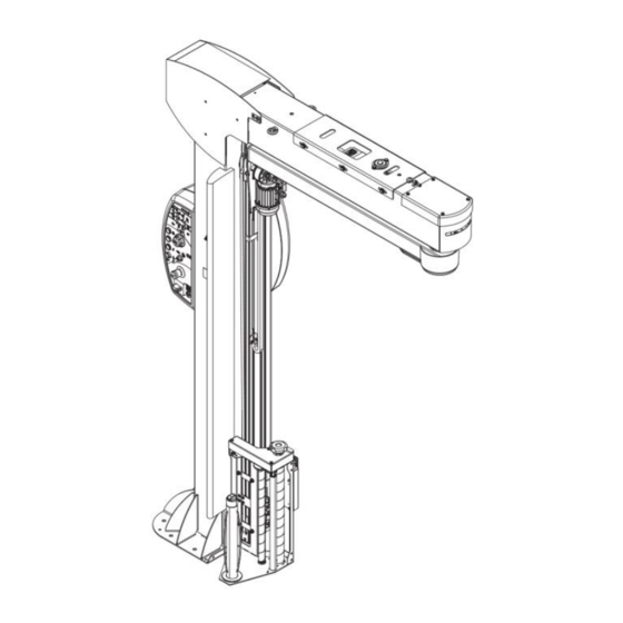
3. TECHNICAL INFORMATION 3.1. MACHINE GENERAL DESCRIPTION The machine is a semi-automatic machine for palletised load wrapping and stabilising with stretch film. The machine must be used only for wrapping and stabilising products contained in packages (in boxes, liquid containers, etc.) with regular shape or with a shape that ensures a stable palletisation. Packages containing liquids or insubstantial materials must have characteristics suitable to the product and be perfectly closed and sealed to prevent the contents from flowing out. - Page 22 The illustration shows, for information purposes only, the machine models, and the legend lists the parts. Legend: 1. Rotary arm It allows the film carriage to rotate around the pallet. 2. Arm motor The motor drives the rotation of the arm. The gearmotor is equipped with brake that keeps the arm locked when stopped in synchronised manner.
-
Page 23: Machine Models Description
3.1.1. MACHINE MODELS DESCRIPTION Table: Film carriage features Film carriage type General features h = 500mm Film carriage of “FR” type with roller with clutch, electromagnetic brake and film stretch adjustment from control panel. Film carriage of “FRD” type with roller with clutch, mechanical brake and manual adjustment of film stretch. -
Page 24: Safety Device Description
3.3. SAFETY DEVICE DESCRIPTION The figure shows the position of the devices on the machine. 1. Main switch: It enables and disables the power supply. It can be locked to prevent unauthorised persons from enabling it during machine adjustment and maintenance phases. 2. -
Page 25: Description Of Electrical Devices
3.4. DESCRIPTION OF ELECTRICAL DEVICES The figure shows the position of the devices on the machine. 1. Gearmotor: it activates the arm rotation. 2. Gearmotor: it activates the film carriage movement. 3. Carriage limit microswitch: it is activated when the film carriage reaches the minimum and maximum wrapping height. 4. -
Page 26: Description Of Accessories On Request
3.5. DESCRIPTION OF ACCESSORIES ON REQUEST To increase the machine performance and versatility, the Manufacturer makes available the following accessories. Reel-holder shaft Ø50 mm (version CORE (1) - CORELESS (2)): A tailstock (3) is also provided with the CORE version for better stability of the reel. - Page 27 6. Longitudinal stop device: Reference device for pallet positioning. 7. Work area delimitation barrier Device to install near the machine to divide the work area from the transit area. 8. Roll container stop device: Device that allows the correct positioning of the roll containers in front of the machine.
- Page 28 9. Template for work area drawing: Template that allows drawing on the ground the pallet positioning area (1) and the machine footprint area (2). 10. Mobile base: Base equipped with counterweight to use the machine without fastening it to the ground. 11.
-
Page 29: Technical Specifications
3.6. TECHNICAL SPECIFICATIONS Description Unit Value measurement Ecowrap XL Masterwrap Ecowrap XL Masterwrap Plus XL Plus FR Plus XL Plus FR h=2000 h=2000 h=2400 h=2400 220-240 1 Ph Supply voltage 220-240 3 Ph 380-415 3 Ph+ N Electrical current frequency 50/60 Installed power Wrapping speed... -
Page 30: Spool Features
3.6.1. SPOOL FEATURES Unit of Description Value measurement Maximum outer diameter (D) Reel height (H) Film thickness μm 7÷35 Internal diameter (d) Ø 50* - Ø 76 Max. weight (*) Install the optional reel-holder shaft TECHNICAL INFORMATION... -
Page 31: Machine Dimensions
3.6.2. MACHINE DIMENSIONS The illustration and the table include the machine dimensional specifications and technical data. Unit of Ecowrap XL Plus Masterwrap XL Ecowrap XL Plus Masterwrap XL measurement FRD h=2000 Plus FR h=2000 FRD h=2400 Plus FR h=2400 2148 2148 2620 2620... -
Page 32: Noise Level
3.7. NOISE LEVEL The values relating to airborne noise have been detected in compliance with standards: UNI EN ISO 3744 EN ISO 11201 Description Average sound pressure Emitted sound power level Level at operator position level (Lpm) (Lwa) (Lop) Operation in working 56,2 dB (A) 72,0 dB (A) 56,5 dB (C) -
Page 33: Information On Handling And Installation
4. INFORMATION ON HANDLING AND INSTALLATION 4.1. RECOMMENDATIONS FOR HANDLING AND LOADING Before performing any operation, the authorised operator must make sure to have understood the “Instructions for use”. Carefully read the “Instructions for use” specified in the manual and those applied directly to the machine and/or the package. -
Page 34: Packing And Unpacking
4.2. PACKING AND UNPACKING The packing is realised, keeping the overall dimensions limited, also in consideration of the transport chosen. To facilitate transport, shipping can be performed with some components disassembled and appropriately protected and packaged. Some parts, especially electrical equipment, are protected with anti-moisture nylon covers. The packages bear all necessary information for loading and unloading. - Page 35 Package in cage INFORMATION ON HANDLING AND INSTALLATION...
-
Page 36: Transport And Handling
4.3. TRANSPORT AND HANDLING Transport, also according to the destination, can be performed with different vehicles. The diagram represents the most used solutions. During transport, in order to avoid sudden movements, adequately anchor the machine to the vehicle. Important For further transportations, recreate the initial packaging conditions for transport and handling. INFORMATION ON HANDLING AND INSTALLATION... - Page 37 Caution - warning Before lifting, check the position of the load's centre of gravity. Package in crate Package on pallet Package with cardboard box Package in cage INFORMATION ON HANDLING AND INSTALLATION...
-
Page 38: Installation Of The Machine
4.4. INSTALLATION OF THE MACHINE The machine must be installed in an area which fulfils the requirements indicated in paragraph “Installation environment characteristics”. If necessary, identify the exact position by plotting the coordinates for correct positioning. Danger - warning Authorised technical service personnel must perform installation and assembly operations. Proceed as follows: 1. - Page 39 3. Hook the lifting device to the eyebolt (A) and lift the column (B). Important Always hook the machine in two points to avoid side tipping. Danger - warning Slowly lift and handle with caution to avoid oscillations. INFORMATION ON HANDLING AND INSTALLATION...
- Page 40 4. Position the base of the column in the installation point. Place the machine on the floor and keep it hooked to the lifting device 5. Drill the holes (ø12 x 110 mm) on the floor in correspondence of the base fastening holes (C). Important Thoroughly clean the holes to eliminate any residual material.
- Page 41 14. Remove the lifting device. 15. Fit the film carriage (L) and fasten it to the support (M) with nuts (N) complete with relevant washers. 16. Connect the connector (P) to the socket (Q). Danger - warning Remove the fastening elements (R) used for transport. INFORMATION ON HANDLING AND INSTALLATION...
-
Page 42: Front Stop Device Installation (Optional)
4.4.1. FRONT STOP DEVICE INSTALLATION (OPTIONAL) 1. Secure the stop device (A) to the base of the column with the screws supplied. 2. Drill the holes (ø10 x 70mm) on the floor in correspondence of the stop device fastening holes. Important Thoroughly clean the holes to eliminate any residual material. -
Page 43: Work Area Delimitation Barrier Installation (Optional)
4.4.3. WORK AREA DELIMITATION BARRIER INSTALLATION (OPTIONAL) 1. Identify the installation position of the barrier (A). 2. Drill the holes (ø10 x 70mm) on the floor in correspondence of the barrier fastening holes. Important Thoroughly clean the holes to eliminate any residual material. 3. -
Page 44: Installation Of Stop Device For Roll Container (Optional)
4.4.4. INSTALLATION OF STOP DEVICE FOR ROLL CONTAINER (OPTIONAL) 1. Position the stop device according to the shown diagram. 2. Drill the holes (ø16 x 70mm) on the floor in correspondence of the stop device fastening holes. Important Thoroughly clean the holes to eliminate any residual material. 3. -
Page 45: Positioning Of Template For Work Area Drawing (Optional)
4.4.5. POSITIONING OF TEMPLATE FOR WORK AREA DRAWING (OPTIONAL) 1. Install template (A) by using the engagement sections and position it resting against the column as indicated in the figure. Important Perform a test rotation at low speed to check the correct alignment of the template with the arm. 2. -
Page 46: Pallet Lifting Frame Installation (Optional)
4.4.7. PALLET LIFTING FRAME INSTALLATION (OPTIONAL) Important Fit the longitudinal members (A) according to the pallet used. 1. Assemble the frame according to the pallet size: fasten the longitudinal members (A) to the front bracket (B) through the screws (C). 2. -
Page 47: Recommendations For Connections
4.5. RECOMMENDATIONS FOR CONNECTIONS Important The connections must be made in accordance with the specifications supplied by the Manufacturer in the enclosed diagrams. The person authorised to carry out said operation must have the skills and experience acquired and acknowledged in the specific sector, must perform the connection in accordance with the best practice and take into account all the regulatory and legislative requirements. -
Page 48: Information On Adjustments
5. INFORMATION ON ADJUSTMENTS 5.1. RECOMMENDATIONS FOR ADJUSTMENTS Before performing any operation, the authorised operator must make sure to have understood the “Instructions for use”. Activate all the safety devices provided, stop the machine and assess whether there is any residual energy before carrying out the operations. -
Page 49: Film Stretch" Adjustment
5.2. “FILM STRETCH” ADJUSTMENT 5.2.1. SPOOL CARRIAGES OF "FRD" TYPE Use the handwheel (A) to adjust the braking action of the stretching roller (B) which determines the film stretch. Clockwise: value increases. Anticlockwise: value decreases. 5.3. REEL BRAKE ADJUSTMENT Use the knob (A) to adjust the braking action of the reel carriage roller (B) which determines the film tensioning. Clockwise: value increases. -
Page 50: Wrapping Machine Arm Drive Chain Tension Adjustment
5.4. WRAPPING MACHINE ARM DRIVE CHAIN TENSION ADJUSTMENT The intervention is required to limit the movement of the arm with braked drive. The figure shows the intervention points and the description indicates the procedures to use. 1. Stop the machine in safety conditions. 2. -
Page 51: Film Carriage Belt Adjustment
5.5. FILM CARRIAGE BELT ADJUSTMENT The figure shows the intervention points and the description indicates the procedures to use. 1. Lift the film carriage (with the machine operating in “manual mode”) until it reaches the “upper” limit switch. 2. Stop the machine in safety conditions. 3. -
Page 52: Information About The Use
6. INFORMATION ABOUT THE USE 6.1. RECOMMENDATIONS FOR OPERATION AND USE When using the machine for the first time, the operator must read the manual and identify the control functions and simulate some operations, especially machine start and stop. Make sure that all safety devices are properly installed and efficient. Only carry out the operations foreseen by the Manufacturer and do not tamper with any device to obtain different performance levels. -
Page 53: Description Of Controls (Ecowrap Plus)
6.2. DESCRIPTION OF CONTROLS (ECOWRAP PLUS) A) Emergency stop button: it is used in case of imminent risk to stop, with a voluntary action, the machine parts which may pose a risk. For further details, see the paragraph “description of safety devices”. B) “Cycle start”... - Page 54 INFORMATION ABOUT THE USE...
-
Page 55: Machine Functions (Ecowrap Plus)
6.2.1. MACHINE FUNCTIONS (ECOWRAP PLUS) To view and/or set the functions, turn or press the multi-function selector. Functional logic diagrams show the navigation modes. The illustration corresponding to each view shows the abbreviation which indicates the activation mode. Abbreviation “R”: turn the control to access the views or to modify the values. - Page 56 Code Ref. activation Icon Description mode Wrapping type program selection “Double wrapping” cycle “Single wrapping” cycle “Double wrapping with feeder” cycle Manual cycle Eco cycle Photocell or Altimeter selection (after having selected the photocell or altimeter (PH), the (P) action is used to access the adjustment mode for the selected parameter) Photocell delay adjustment via the rotation of the multi-function selector.
- Page 57 Carriage “Home” height adjustment Carriage “Home” height adjustment, by rotating the multi-function selector, the height can be adjusted at 5-centimetre intervals, up to a maximum height of 1 metre Carriage upstroke / downstroke speed adjustment Carriage upstroke / downstroke speed adjustment via the rotation of the multi- function selector.
-
Page 58: Multi-Function Selector Usage Mode (Ecowrap Plus)
6.3. MULTI-FUNCTION SELECTOR USAGE MODE (ECOWRAP PLUS) To select the wrapping cycle: 1. Turn the selector to the first function on the line on the upper left (F1). 2. Press the selector (D). The LED starts flashing. 3. Turn the selector to select the number of the work cycle. - Page 59 To view the production data: Activate the main electrical disconnector and at the same time press selector (D). The following message appears on the display (E): "d1” cycle partial counter. To reset, briefly hold the selector down (for about 3 seconds).
-
Page 60: Turning The Machine On And Off (Ecowrap Plus)
6.4. TURNING THE MACHINE ON AND OFF (ECOWRAP PLUS) 1. Turn the main switch (A) to “I” (ON) to activate the power supply. The LEDs turn on to indicate that the system is running machine check-up routine and the display (E) shows the installed software version for a few seconds. -
Page 61: Cycle Start And Stop (Ecowrap Plus)
6.5. CYCLE START AND STOP (ECOWRAP PLUS) Proceed as follows. 1. Place the pallet in the wrapping area within the rotary arm trajectory and move the loading device away. 2. Tie the film end to the pallet. 3. Set the cycle parameters. 4. -
Page 62: Emergency Stop And Restart (Ecowrap Plus)
6.6. EMERGENCY STOP AND RESTART (ECOWRAP PLUS) Proceed as follows. 1. Press the emergency button (A) of the machine in situations of imminent risk. Its functions stop immediately. 2. After setting the working conditions back to normal, release the button to allow the machine to resume operation. 3. -
Page 63: Description Of Controls (Masterwrap Plus)
6.7. DESCRIPTION OF CONTROLS (MASTERWRAP PLUS) A) Emergency stop button: it is used in case of imminent risk to stop, with a voluntary action, the machine parts which may pose a risk. For further details, see the paragraph “description of safety devices”. B) “Cycle start”... - Page 64 INFORMATION ABOUT THE USE...
-
Page 65: Description Of User Interface (Masterwrap Plus)
6.8. DESCRIPTION OF USER INTERFACE (MASTERWRAP PLUS) The user interface is equipped with a multi-function selector (D), which is used to view and set the machine functions, and a display (E), which shows recipes, parameters, etc. To view and/or set the functions, turn or press the multi-function selector. Functional logic diagrams show the navigation modes. -
Page 66: Main Menu" Page
6.9. "MAIN MENU" PAGE Ref. Button Description Wrapping cycle Arm rotation speed (rpm) Carriage speed Wrapping end delay Access to “Manual Controls” Menu. (See “Manual Controls Menu”) Access to “Film Tensioning” Menu (See “Film tensioning menu) Access to “Other” Menu (See “Other Menu”) Intermediate wrapping turns Intermediate and upper wrapping turns Access to “Settings”... -
Page 67: Wrapping Cycle
6.9.1. WRAPPING CYCLE Activation mode Button Description abbreviation “Double wrapping” cycle “Single wrapping” cycle “Double wrapping with feeder” cycle INFORMATION ABOUT THE USE... -
Page 68: Arm Rotation Speed (Rpm)
6.9.2. ARM ROTATION SPEED (rpm) Activation mode Button Description abbreviation View arm rotation speed (rpm) INFORMATION ABOUT THE USE... -
Page 69: Carriage Speed
6.9.3. CARRIAGE SPEED Activation Ref. mode Button Description abbreviation Display carriage speed Display carriage upstroke speed Display carriage downstroke speed INFORMATION ABOUT THE USE... -
Page 70: Wrapping End Delay / Pallet Height
6.9.4. WRAPPING END DELAY / PALLET HEIGHT Activation Ref. mode Button Description abbreviation View the distance of the wrapping end delay in cm View the dimension of the offset from the ground in cm View the set pallet height View the dimension of the offset from the ground in cm INFORMATION ABOUT THE USE... -
Page 71: Manual Controls
6.9.5. MANUAL CONTROLS Activation mode Button Description abbreviation Press the button (5) to access the “Manual controls” Menu. Activation mode Button Description abbreviation If “JOG” is pressed, the carriage (hold to run) rises until reaching the upper limit switch If “JOG” is pressed, the arm (hold to run) turns until reaching the initial position If “JOG”... -
Page 72: Film Tensioning
6.9.6. FILM TENSIONING For PGS version only Activation Ref. mode Button Description abbreviation View the film tensioning value View the lower film tensioning value View the film upstroke tensioning value View the upper film tensioning value View the film downstroke tensioning value INFORMATION ABOUT THE USE... -
Page 73: Other
6.9.7. OTHER Activation mode Button Description abbreviation Press the button (7) to access the “Other” Menu. Activation mode Button Description abbreviation “Copy recipe” function “Ergonomic upstroke” function Code Icon activation Page Description ref. mode Selection of the carriage stop height in cm at the end of the cycle Select the numbers of the source and target recipes on which you wish to copy the values. -
Page 74: Settings
6.9.8. SETTINGS Activation mode Button Description abbreviation Press the button (10) to access the settings Menu. Activation mode Button Description abbreviation Cycle counter Acoustic signal User. Page alternative options depend on the login status Panel lock Function to change the panel lock password (Available depending on to the login status and with unlocked panel) R-Connect device status Motor parameters - Assistance page... - Page 75 Load cell settings (PGS only) Info - Assistance page Return to the previous menu INFORMATION ABOUT THE USE...
- Page 76 Activation Icon mode Page Description Ref. abbreviation View counters P = Partial T = Total H = hours FILM dm = decimetres of film unwound by the machine during the wrapping cycle FILM g/5m = weight of the used film expressed in grams/5 metres FILM cycle = decimetres of film unwound by the machine during the last wrapping cycle...
- Page 77 To change the panel lock password, enter a new password and select the “checkmark”. Enter the chosen password again and confirm to update its value. CELL = Load cell reading instant value. OFFSET = Offset value (with film tensioning = 0). Press and keep pressed (for about 3 seconds) to set the parameter (only after logging in).
-
Page 78: Recipe
6.9.9. RECIPE Activation mode Button Description abbreviation Programme Code Icon activation Page Description ref. mode Programme “1” Programme “2” Programme “3” Programme “4” Programme “5” Programme “6” INFORMATION ABOUT THE USE... - Page 79 Manual cycle (See “Manual Cycle”) “ECO” cycle (See “Eco Cycle”) INFORMATION ABOUT THE USE...
-
Page 80: Manual Cycle
6.9.10. MANUAL CYCLE Activation mode Button Description abbreviation Press the button (12) to access the manual cycle menu Home page Set the arm rotation speed, the carriage upstroke/downstroke speed and the film stretch as previously indicated in programmes from 1 to 6. Activation mode Button... - Page 81 When the “START” button is pressed, the arm starts to turn and the Home page looks as follows. Activation mode Button Description abbreviation Arm rotation speed Carriage upstroke/downstroke speed Film stretch (for FR-PGS version only) Carriage downstroke At every pressure, the carriage moves down or stops Carriage upstroke At every pressure, the carriage moves down or stops Arm stop in initial position...
-
Page 82: Eco Cycle
6.9.11. ECO CYCLE Activation mode Button Description abbreviation Press the button (12) to access the self-learning cycle Home page. Activation mode Button Description abbreviation Start logging mode Manual controls Film stretch (for FR-PGS version only) Other menu Settings Synchronisation of the machine INFORMATION ABOUT THE USE... - Page 83 Activation mode Button Description abbreviation Press the “Start logging mode” button (1) to access the logging mode. Set the arm rotation speed, the carriage upstroke/downstroke speed and the film stretch as previously indicated in programmes from 1 to 6. Once any of these control buttons has been pressed, these values can no longer be modified.
- Page 84 Activation mode Button Description abbreviation When the button is pressed, the arm starts to turn. Use the buttons to perform the required movements. Press the jog button to confirm the selected control. Press the “STOP” button to end the logging. INFORMATION ABOUT THE USE...
-
Page 85: Miscellaneous
6.9.12. MISCELLANEOUS 1. Press the “Reset” button. 2. Press the "Cycle Start" button. Restart from feeder cycle. 3. Home page if the film stretch function is absent. 4. Emergency bypassed. The carriage can be lifted (using the “start” button) even in case of carriage emergency. 5. -
Page 86: Turning The Machine On And Off (Masterwrap Plus)
6.10. TURNING THE MACHINE ON AND OFF (MASTERWRAP PLUS) 1. Turn the main switch (J) to “I” (ON) to activate the power supply. The displayed icon indicates that the “Reset” button (F) must be pressed. 2. Press the “Reset (F)” button. 3. -
Page 87: Description Of The Wrapping Cycles
6.12. DESCRIPTION OF THE WRAPPING CYCLES 6.12.1. SINGLE WRAPPING CYCLE 1. Turn the jog control to enable the wrapping cycle page. 2. Press the jog control and select the single wrapping. 3. Press the jog control to confirm. 4. The film carriage starts moving from the pallet base and stops when it reaches the upper end, after having performed the required number of wrapping turns at the base and at the upper end of the pallet. -
Page 88: Wrapping Cycle With Feeder
6.12.3. WRAPPING CYCLE WITH FEEDER To select the cycle: 1. Turn the jog control to enable the wrapping cycle page. 2. Press the jog control and select the wrapping with feeder. 3. Press the jog control to confirm. The machine performs a cycle aimed at making it easier for the operator to completely cover the pallet and ensuring the higher possible level of protection. -
Page 89: Cycle Start And Stop (Masterwrap Plus)
6.13. CYCLE START AND STOP (MASTERWRAP PLUS) Proceed as follows. 1. Place the pallet inside the rotary arm operating area and move the loading device away. 2. Lock the film end to the pallet. 3. Set the wrapping mode. For more details, see the paragraph “Description of user interface”. Caution - warning Do not stretch or pre-stretch the film excessively and do not wrap the product with too many wrapping turns to prevent damaging the packages and the products contained in them. -
Page 90: Emergency Stop And Restart (Masterwrap Plus)
6.14. EMERGENCY STOP AND RESTART (MASTERWRAP PLUS) Proceed as follows. 1. Press the emergency button (A) of the machine in situations of imminent risk. Its functions stop immediately. The cycle will reset. 2. After setting the working conditions back to normal, release the button to allow the machine to resume operation. 3. -
Page 91: Spool Loading
6.15. SPOOL LOADING Carriage FR - FRD 1. Insert the reel in the relevant seat on the film carriage, with adhesive side prepared according to the required wrapping modes. Carriage FRD 2. Gather the film making a thin rope and route it through the rollers (M) and (N). - Page 92 Carriage FR - FRD 5. Block the film edge at the pallet’s corner. INFORMATION ABOUT THE USE...
-
Page 93: Maintenance Information
7. MAINTENANCE INFORMATION 7.1. RECOMMENDATIONS FOR MAINTENANCE Proper maintenance will allow a longer life span and constant compliance with safety requirements. Before performing any operation, the authorised operator must make sure to have understood the “Instructions for use”. Pay attention to the safety warnings, do not misuse the machine and assess the possible residual risks. Carry out the interventions with all the safety devices enabled and wear the required PPE. -
Page 94: Periodical Maintenance Intervals
7.2. PERIODICAL MAINTENANCE INTERVALS Important Keep the machine in maximum efficiency conditions and perform all the scheduled maintenance operations provided for by the Manufacturer. Proper maintenance will provide the best performance, a longer life span and constant compliance with safety requirements. Maintenance interval table Frequency Component... - Page 95 Every 20000 Arm rotation chain Wear check Have the chain Contact the assistance cycles or every replaced if it is worn service year Carriage Wear check Have the component Contact the assistance movement replaced if it is worn service assistance belt Carriage sliding Wear check Have the components...
-
Page 96: Lubrication Point Diagram
7.3. LUBRICATION POINT DIAGRAM The diagram shows the main parts concerned by the lubrication interventions and their intervals. Spread grease over it. Lubricate with spray silicone grease. MAINTENANCE INFORMATION... -
Page 97: Lubricant Table
7.4. LUBRICANT TABLE The table below lists the specifications of the lubricants recommended by the Manufacturer for each component and/or reference area. Use lubricants (oils and greases) recommended by the Manufacturer or with similar chemical-physical features. Lubricant characteristics Lubricant type Code Parts to be lubricated Mineral oil... -
Page 98: Fault Information
8. FAULT INFORMATION 8.1. ALARM MESSAGES In the event of a breakdown during operation the machine stops automatically and alarm messages appear on the display. The table lists the displayed messages, the type of problem, the causes and possible solutions. Important For these operations a precise technical expertise or ability is required;... -
Page 99: Alarm List (Masterwrap Plus)
8.1.2. ALARM LIST (MASTERWRAP PLUS) Code Problem Cause Solution E001 Emergency stop alarm Emergency push-button Reset by turning the button in the pressed direction of the arrow and press “Reset” E002 Emergency plate at the Emergency plate pressed. Rotate the key-operated switch (G) film carriage base... -
Page 100: Problem List (Ecowrap Plus - Masterwrap Plus)
8.1.3. PROBLEM LIST (ECOWRAP PLUS - MASTERWRAP PLUS) Problem Cause Solution carriage vibrates Excessive friction on the guide Clean the guide, lubricate it with silicone oil or spray during the stroke without grease. film Excessive wear of sliding Replace sliding guide shoes guide shoes Poor belt tension Check the belt tension verifying that the tensioning... - Page 101 Poor drive force on rotary Excessive friction on rotary Contact technical support. arm drive parts. Brake on rotation motor not Adjust the brake gap on the arm rotation motor. released Contact technical support. Rubber roller jammed Reduce the tension through the braking knob on- carriage board the carriage.
-
Page 102: Replacement Information
9. REPLACEMENT INFORMATION 9.1. RECOMMENDATIONS FOR REPLACING MACHINE PARTS Before performing any operation, the authorised operator must make sure to have understood the “Instructions for use”. Carry out the interventions with all the safety devices enabled and wear the required PPE. Demarcate the surrounding areas and put in place adequate safety measures, as provided for by the standards on workplace safety, in order to prevent and minimise the risks. -
Page 103: Recommended Spare Parts List
9.2. RECOMMENDED SPARE PARTS LIST List of the spare parts that wear easily and that should be always available to avoid long machine downtimes: Drive chain. Drive belt. Idle pulley bushings. Sliding guide shoes. To order them, contact your local dealer and refer to the spare parts catalogue. Important Replace worn parts with original spare parts. -
Page 104: Annexes
Robopac S.p.A. will in no case be held responsible for any losses due to lack of production or injuries to persons or damage to things caused by malfunctions or forced downtime of the machine covered by the warranty. - Page 105 ANNEXES...
- Page 107 ROBOPAC SPA Via Fabrizio da Montebello, 81 – 47892 Gualdicciolo, Repubblica S. Marino (RSM) Phone (+378) 0549 910511 - Fax (+378) 0549 908549 – 905946 http://www.aetnagroup.com...
Need help?
Do you have a question about the ECOWRAP PLUS XL FRD and is the answer not in the manual?
Questions and answers
Доброе утро. Столкнулся с ошибкой Е83 при обмотке продукции черного цвета
Error E083 on the Robopac XL FRD indicates a "Communication alarm" and an "Electronic fault." The recommended action is to contact technical support.
This answer is automatically generated