Table of Contents
Advertisement
Quick Links
ENG
USE AND MAINTENANCE MANUAL
Rotating ring band wrapping machine
ORBIT 16
Translation of the original instructions
3709301866.0
Instructions manual code:
0616
English Edition:
Serial number |_|_|_|_|_|_|_|_|_|_|
Attention
Read and understand these instructions before using the machine.
Keep this handbook for further consultation.
ROBOPAC S.p.A.
Advertisement
Table of Contents

Subscribe to Our Youtube Channel
Related Manuals for Robopac ORBIT 16


Summary of Contents for Robopac ORBIT 16
- Page 1 USE AND MAINTENANCE MANUAL Rotating ring band wrapping machine ORBIT 16 Translation of the original instructions 3709301866.0 Instructions manual code: 0616 English Edition: Serial number |_|_|_|_|_|_|_|_|_|_| Attention Read and understand these instructions before using the machine. Keep this handbook for further consultation.
-
Page 2: Table Of Contents
ORBIT 16 Summary GENERAL INFORMATION 1.1. PURPOSE OF THE MANUAL 1.2. MANUFACTURER AND MACHINE IDENTIFICATION 1.3. TERMS AND DEFINITIONS 1.4. MODES OF REQUESTING FOR ASSISTANCE 1.5. ATTACHED DOCUMENTATION 1.6. HOW TO READ THE DIRECTIONS FOR USE SAFETY INFORMATION 2.1. GENERAL SAFETY PRECAUTIONS 2.2. - Page 3 ORBIT 16 INFORMATION ON ADJUSTMENTS 5.1. RECOMMENDATIONS FOR ADJUSTMENTS 5.2. ROLLER GUIDE ADJUSTMENTS (OPTIONAL) 5.3. PRESSURE UNIT ADJUSTMENT 5.4. PRESSURE PLATEN PRESSURE ADJUSTMENT 5.5. FRICTION ADJUSTMENT ON REEL CARRIAGE 5.6. PRE-STRETCH ADJUSTMENT ABOUT THE USE 6.1. RECOMMENDATIONS FOR OPERATION AND USE 6.2.
- Page 4 ORBIT 16 8.1. SOME SUGGESTIONS ON OPERATION 8.2. ALARM MESSAGES SPARE PARTS REPLACEMENT INFORMATION 9.1. RECOMMENDATIONS FOR REPLACING PARTS 9.2. FILM CUTTING BLADE REPLACEMENT 9.3. LIST OF ESSENTIAL SPARE PARTS 9.4. MACHINE DISPOSAL AND SCRAPING 10. ENCLOSED DOCUMENTATION 10.1. WARRANTY CONDITIONS 10.2.
-
Page 5: General Information
These instructions for use describe the two machine versions intended for: ‒ wrapping short products, equipped with base guards, identified by the logo Orbit 16 B (for the size of the processable products, see the diagram in Section “Technical data”). -
Page 6: Terms And Definitions
ORBIT 16 Machine model. Machine’s serial number. Year of manufacture. Mains voltage. Mains frequency. Number of phases. Absorption. Total installed power. Air consumption. Maximum pressure. Mass. Manufacturer and address. 1.3. TERMS AND DEFINITIONS Some recurring terms found within the manual are described in order to provide a more complete image of their meanings. -
Page 7: Modes Of Requesting For Assistance
Operator. 1.4. MODES OF REQUESTING FOR ASSISTANCE The distribution network ROBOPAC is at your service for any problem that requires technical support, to order spare parts, and for whatever new type of need that can help develop your business. -
Page 8: Safety Information
ORBIT 16 2. SAFETY INFORMATION 2.1. GENERAL SAFETY PRECAUTIONS ― Carefully read the “Directions for use”, paying particular attention to the “Residual risks”. ― Pay attention to the safety warnings. ― Use the machine only for the use for which it is designed. -
Page 9: Safety Warnings For Use And Operation
ORBIT 16 2.3. SAFETY WARNINGS FOR USE AND OPERATION ― The operator must be trained and possess the proper knowledge required to carry out the specific tasks and must meet the conditions required for the safe use of the machine. -
Page 10: Employer Obligations
ORBIT 16 2.4.2.EMPLOYER OBLIGATIONS ― The operator must possess the required training and meet the suitable conditions for carrying out the activities in safety conditions. ― The employer must inform the operator on the INCORRECT USES predictable and on the persistent Residual risks. -
Page 11: Information And Safety Signals
ORBIT 16 ― Take all necessary precautions (suitably mark the working area and the exits, ensure proper visibility, provide all necessary supporting equipment, etc.) to ensure safe operation. ― Delimitate the work area to minimise the risks, as per the workplace safety and health regulations. - Page 12 ORBIT 16 Electrical hazard sign Electrical shock danger: do not access within elements under tension. Information sign It shows the insertion points for the lifting forks. Prohibition sign Do not operate the component with your hands. Hazard sign Danger of cutting.
- Page 13 ORBIT 16 Hazard sign Hand crushing danger. Information sign Film winding diagram. Information sign Indicates the points for lifting with a hook device. Important Check that the plates are clearly readable, and, if necessary, replace them with new ones that shall be positioned in the same places as previously.
-
Page 14: Technical Information
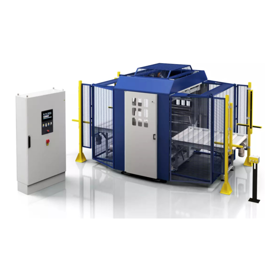
ORBIT 16 3. TECHNICAL INFORMATION 3.1. MACHINE GENERAL DESCRIPTION ‒ The above mentioned machine is a stretch film banding machine intended to spiral wrap products of varying size and shape. ‒ Readily available reel of stretch film are used for wrapping. - Page 15 ORBIT 16 Base the main structure of the machine. Control panel Enables machine functions. Infeed/outfeed conveyors They allow transportation of the product to be wrapped; they are comprised of motorised rollers, with or without conveyor. Rotating ring unit Consists of a rotating ring with friction drive, driven by an inverter-controlled electric motor.
-
Page 16: Description Of The Operation Cycle
ORBIT 16 Driving axle (Optional) Additional sheets to that already present to support short products (Not shown). Guide (Optional) adjust the width for product containment. Reel support unit with jumper Composed of a fast loading spool carriage spindle, two idler rollers that adjust the wrapping tension and a coating recovery device. - Page 17 ORBIT 16 Phase 1 ‒ The conveyor starts and moves the product towards the rotating ring. ‒ The product engages photocell (B1), the infeed pressure platen lowers and blocks the product, the “head positioning” timer starts. ‒ After the timer count has finished, the carrier stops, the rotating ring starts counting the "head and tail turns";...
- Page 18 ORBIT 16 Phase 2 ‒ When the “head and tail revolution” count is completed, the conveyor restarts and product length wrapping begins. ‒ The product moves forward and engages photocell (B2), the outfeed pressure platen lowers on the product while the machine continues to wrap product.
-
Page 19: Head - Tail" Wrapping
ORBIT 16 3.2.2."HEAD - TAIL" WRAPPING With the product on the feed conveyor, press the “Start” button on the control panel to start the work cycle. Phase 1 ‒ The conveyor starts and moves the product towards the rotating ring. - Page 20 ORBIT 16 Phase 2 ‒ Infeed/outfeed conveyors starts. ‒ The product moves forward and engages photocell (B2). ‒ The outfeed pressure platen lowers on the product. Phase 3 ‒ The product moves forward disengaging photocell (B1), the infeed pressure platen lifts and the ring starts rotation.
-
Page 21: Complete" Wrapping And "Central Bands
ORBIT 16 3.2.3."COMPLETE" WRAPPING AND "CENTRAL BANDS" With the product on the feed conveyor, press the “Start” button on the control panel to start the work cycle. Phase 1 ‒ The conveyor starts and moves the product towards the rotating ring. - Page 22 ORBIT 16 Phase 2 ‒ Once the "reinforcing revolutions" count has been completed, the conveyor restarts and the product is wrapped longitudinally. ‒ The product moves forward and engages photocell (B2), the outfeed pressure platen lowers on the product while the machine continues to wrap product.
- Page 23 ORBIT 16 Phase 5 ‒ After the “Reinforcement turns” count has finished, the rotating ring stops and the pad (A) moves up, locking the film against the stopper (C). If there is a sealing unit installed, the coating gets sealed as the pad moves The gripper returns to its position and locks the coating.
-
Page 24: Head-Tail" And "Central Belts" Wrapping
ORBIT 16 3.2.4."HEAD-TAIL" AND "CENTRAL BELTS" WRAPPING With the product on the feed conveyor, press the “Start” button on the control panel to start the work cycle. Phase 1 ‒ The conveyor starts and moves the product towards the rotating ring. - Page 25 ORBIT 16 Phase 2 ‒ Infeed/outfeed conveyors starts. ‒ The product moves forward and engages photocell (B2). ‒ The outfeed pressure platen lowers on the product. Phase 3 ‒ The "central bands" timer starts counting; at count completed, the conveyor stops, the rotating ring starts and counts the "reinforcing revolutions"...
- Page 26 ORBIT 16 Phase 5 ‒ After the “Head and tail turns” count has finished, the rotating ring stops and the pad (A) moves up, locking the film against the stopper (C). If there is a sealing unit installed, the coating gets sealed as the pad moves The gripper returns to its position and locks the coating.
-
Page 27: Head And Additional Bands" Winding
ORBIT 16 3.2.5.“HEAD AND ADDITIONAL BANDS” WINDING With the product on the feed conveyor, press the “Start” button on the control panel to start the work cycle. Phase 1 ‒ The conveyor starts and moves the product towards the rotating ring. - Page 28 ORBIT 16 Phase 3 ‒ The "additional bands" timer starts counting; at count completed, the carrier stops, the rotating ring starts and counts the "reinforcement turns" set; the product is wrapped with the number of reinforcement turns set. ‒ At the last wrap of the rotating ring, the clamp comes out to hook the film.
-
Page 29: Safety Device Descriptions
ORBIT 16 3.3. SAFETY DEVICE DESCRIPTIONS The figure shows the positioning of the devices on board of the machine. Master switch This allows the machine to be disconnected from power and to be locked in order to prevent tampering by outside parties. - Page 30 Movable safety guards They prevent access to the internal parts of the machine. Light curtains (Orbit 16 M version only) They stop the machine when their beam is interrupted by any other object than the product to be wrapped.
-
Page 31: Description Of The Electrical Devices
ORBIT 16 3.4. DESCRIPTION OF THE ELECTRICAL DEVICES The figure shows the positioning of the devices on board of the machine. Photocell (B1) detects product presence on the infeed conveyor. Photocell (B2) detects product presence on the outfeed conveyor. Phase sensor (SQ1) Detects the rotating ring in the start cycle position (machine in phase). -
Page 32: Pneumatic Device Description
ORBIT 16 Sensor It detects that the rotating ring is stopped. Photocell It detects that the inlet pressure roller is in down position and sends a first descent command to the outlet pressure roller. Sensor It detects any coating breakage. -
Page 33: Accessories Available Upon Request (Optional)
ORBIT 16 Gradual starter control valve Closes compressed air supply when power is disconnected. Progressive starter Allows you to pressurise the machine circuit gradually. Pressure switch It detects the line pressure when it drops below the set value and puts the machine in emergency condition. -
Page 34: Product Size
ORBIT 16 Rotating ring speed (max) Product infeed speed (max) m/min Product infeed speed (min) m/min Worktable height STD 825 optional 1150 3.7.1.PRODUCT SIZE The dimensions (width and height) of the products that can be processed must be kept within the limits marked on the chart. -
Page 35: Processable Products Size (Guards Muting)
ORBIT 16 ‒ for Hmin = 20 => Wmin =350 ‒ Minimum length (bob.250)=650 ‒ Minimum length (bob.500)=900 ‒ Maximum height =220 3.7.3.PROCESSABLE PRODUCTS SIZE (GUARDS MUTING) Worktable Pressure roller overall dimensions (Posit. STANDARD) Pressure roller overall dimensions (Posit. MAXIMUM HEIGHT) Minimum workable dimensions (mm): ‒... -
Page 36: Machine Dimensions
ORBIT 16 3.7.4.MACHINE DIMENSIONS Orbit 16 B Orbit 16 M 3698 4396 2406 2406 2403 2403 H ¹ 1110 1110 36/95... -
Page 37: Coating
ORBIT 16 3.7.5.COATING Orbit 16 Thickness μm 17 - 50 3.8. SURROUNDING AREAS Operator station: loading and cycle start area ¹. Sorrounding area. Product outfeed area. These areas must be suitably sized to the product being processed. 3.9. NOISE LEVEL While working, the machine reaches the noise levels shown in the table. -
Page 38: Installation Environment Characteristics
ORBIT 16 Description Average Acoustic power output (LW) Level at the level of operator's pressure on place (Lop) measurement surface (Lpm) Empty operation 47.0 dB (A) 63.0 dBw (A) 0.00 mW (A) 52.7 dB (A) Functioning in working 67.9 dB (A) 83.8 dBw (A) -
Page 39: Information On Handling And Installation Operations
ORBIT 16 4. INFORMATION ON HANDLING AND INSTALLATION OPERATIONS 4.1. RECOMMENDATIONS FOR HANDLING AND LOADING Important Accomplish handling and loading according to the instructions supplied by the manufacturer to be found on the machine and in the operating instructions. The person authorized to accomplish these operations must, if necessary, organise a "safety plan"... -
Page 40: Transport And Handling
ORBIT 16 Package in crate 4.3. TRANSPORT AND HANDLING Transport, also according to the destination, can be performed by different vehicles. The diagram represents the most popular solutions. During transport, with the purpose to avoid sudden movements, adequately anchor the machinery to the means of transportation. -
Page 41: Handling And Lifting
ORBIT 16 4.4. HANDLING AND LIFTING The machine can be handled with a fork or hook lift truck having adequate capacity. Position a lifting device as indicated in the figure. Caution - Warning Before lifting the machine, check for centering position of the load. - Page 42 ORBIT 16 Place the machine in the area assigned for assembly. Important It must be placed on a smooth, level surface for assembly. Use the support feet to level the machine. The machine can be fastened to the floor, if required, by drilling holes in the walls prepared on the support feet.
-
Page 43: Carriers Installation
ORBIT 16 4.5.2.CARRIERS INSTALLATION Remove packing from conveyors Remove the screws that fasten the conveyors. Connect the conveyor and support it as to prevent damage to the conveying belt. Lift the conveyor and screw the adjusting legs to it. Connect the infeed carrier to the base and tighten the screws (C). - Page 44 ORBIT 16 Connect the outfeed carrier to the base and tighten the screws (D). Use the support feet to level the machine. Connect the connectors to the photocells (M - L). Connect the connectors of the motors (I - H).
- Page 45 ORBIT 16 Connect the air hoses (V) to the gripper/cutter/welder. Connect the connectors (Z) of the gripper/cutter/welder sensors. Install the inlet and outlet guards (N) and (O). 45/95...
- Page 46 ORBIT 16 For Orbit 16 M version only: Install the inlet and outlet guards (N - O - P). ‒ Fix the light curtains (R - S) to the guards (P). ‒ Secure the supports of the light curtains to the ground.
-
Page 47: Recommendations For Connections
ORBIT 16 ‒ Place the control panels (T - U) and fix them to the ground. Make the electrical connections between the panel and the electric cabinet. 4.6. RECOMMENDATIONS FOR CONNECTIONS Important The connections must be made in accordance with the specifications supplied by the manufacturer in the enclosed diagrams. -
Page 48: Electrical Connection
ORBIT 16 4.8. ELECTRICAL CONNECTION Standard models work with a mains voltage of: ‒ 400 V 3Ph+N 50/60 Hz Proceed as follows for electrical connections. Check that the mains voltage (V) and frequency (Hz) correspond to those of the machine. -
Page 49: Information On Adjustments
ORBIT 16 5. INFORMATION ON ADJUSTMENTS 5.1. RECOMMENDATIONS FOR ADJUSTMENTS ‒ Before performing any operation, the authorised operator must make sure that he/she understood the "Instructions for use". ‒ Pay attention to the SAFETY WARNINGS, do not use the machine for UNSPECIFIED PURPOSES and assess the possible RESIDUAL RISKS. -
Page 50: Pressure Unit Adjustment
ORBIT 16 When wrapping very wide products, guide supports must be moved after having loosened the handles (B). 5.3. PRESSURE UNIT ADJUSTMENT Height position When processing round and high products, move the pressure units in top position: Disassemble the support by removing screws (B). -
Page 51: Pressure Platen Pressure Adjustment
ORBIT 16 5.4. PRESSURE PLATEN PRESSURE ADJUSTMENT Based on the type of product, adjust pressure using the knob (A) so that the pressure platens securely hold the product without deforming it. Pressure can be read on the pressure gauge (B). -
Page 52: Friction Adjustment On Reel Carriage
ORBIT 16 5.5. FRICTION ADJUSTMENT ON REEL CARRIAGE The clutch of the spool carriage roller prevent the reel from winding to much during the cycle due to inertia. The optimum adjustment must be performed with the heaviest spool available, that is, the one with greater... -
Page 53: Pre-Stretch Adjustment
ORBIT 16 5.6. PRE-STRETCH ADJUSTMENT Display the main page. Touch the key (A) to access the manual movements (see section 6.3. “Description of the operating terminal” - “Description of manual controls”). Touch the wheel (B) key to enable it and then the "reel"... -
Page 54: About The Use
ORBIT 16 6. ABOUT THE USE 6.1. RECOMMENDATIONS FOR OPERATION AND USE ‒ Before performing any operation, the operator must make sure that he/she understood the "Instructions for use". ‒ When using the machine for the first time, the operator must read the manual and identify the controls and simulate some operations, especially the start-up and shutdown. -
Page 55: Display In Operation
ORBIT 16 Green restart push-button ‒ When the green light is on, it means that the light curtains are enabled. ‒ When the light is off, it means that the light curtains are engaged and the machine is in emergency condition. -
Page 56: Using The Panel
ORBIT 16 6.3.1.USING THE PANEL Switching on the machine the introduction page is displayed. It contains. ‒ Manufacturer’s name. ‒ Press the "Reset" button. ‒ Machine ready; the main page is being displayed. ‒ Press the "Start" button to enable the... -
Page 57: Main Page
ORBIT 16 6.3.2.MAIN PAGE The page displays the wrapping parameters currently in use and gives access the other pages. Displays the name of the recipe in use. Key to access the no. of windings setting (see 6.5. “Cycle parameter setting”). -
Page 58: Operator And Password Change Key
ORBIT 16 6.3.3.OPERATOR AND PASSWORD CHANGE KEY Some settings can only be accessed by the machine Manager after entering the password (editable), in order to prevent unauthorized personnel from changing the password. Caution - Warning The factory responsible should assign... -
Page 59: Default Password Reset
ORBIT 16 If correct, confirm by tapping the key (F) and confirm again in the pop UP window by tapping the key (G). 6.3.4.DEFAULT PASSWORD RESET If you need to restore the default password in case you have forgotten the... -
Page 60: General Parameters Settings
ORBIT 16 6.3.5.GENERAL PARAMETERS SETTINGS Press the key (C) from the main screen to open the “General parameters” screen. ‒ Press the key (1) to open the “Production counters” screen. ‒ Press the key (2) to open the “H.M.I. settings” screen (See 6.3.6. “Software settings and displays“). - Page 61 ORBIT 16 ‒ Press the key (3) to open the “Login password” window (See 6.3.3.1. “Operator change“). ‒ Tap the key (4) to open the password change window (See 6.3.3.2. “Password change“). ‒ Tap the key (5) to open the “product loading and unloading”...
-
Page 62: Software Settings And Displays
ORBIT 16 6.3.6.SOFTWARE SETTINGS AND DISPLAYS ‒ Tap the key (C) from the main screen to open the general parameters screen. ‒ Tap the key (2) to open the “H.M.I Permissions” screen. 62/95... - Page 63 ORBIT 16 2.1) Set the light intensity of the display. 2.2) See the software version information. 2.3) To set the date and time,. 63/95...
- Page 64 ORBIT 16 2.4) Display information on machine status for assistance purposes. 2.5) Display a summary of machine last alarms tripped. 2.6) Enable / disable the sound by pressing the keys. ‒ Change the various parameters, confirm with "ESC" push-button (A).
-
Page 65: Date And Time Setting
ORBIT 16 6.3.7.DATE AND TIME SETTING For this operation proceed in the following way. Display the main page (see 6.3. “Operating terminal description” - “Main screen“). Tap the key (C) to open the general parameters screen. Touch the key (3) and... -
Page 66: Modification Mode Regarding The Settings
ORBIT 16 Rotation of the reel change / wheel. Incoming product pressure unit ascent/descent. Outgoing product pressure unit ascent/descent. The product infeed/outfeed pulling unit forward/backward. Clamping unit exit/retraction. For example, by touching the image of the wheel (B) it will be displayed the key (C) (blue, therefore enabled). -
Page 67: Written Editings And Values
ORBIT 16 Important The performed modifications become instantly operative and stored automatically. 6.4.1.WRITTEN EDITINGS AND VALUES The keypad is displayed each time the editable or programmable functions are enabled. Digit the requested value or name and confirm by pressing the "Enter" (1) key. -
Page 68: Copy Recipes" Function
ORBIT 16 6.4.3.“COPY RECIPES” FUNCTION For this operation proceed in the following way: Display the main page (See 6.4.1. "Main screen"). Press key (A) to view the list of recipes. Press the key (B) to open the “Copy Recipes” screen. -
Page 69: Cycle Parameter Setting (Recipe Composition)
ORBIT 16 6.5. CYCLE PARAMETER SETTING (RECIPE COMPOSITION) For this operation proceed in the following way. Display the main page (see 6.3. “Operating terminal description” - “Main screen“). Tap the key (C) to open the general parameters screen. Touch the key (3) and access via password, as machine manager (see 6.3. - Page 70 ORBIT 16 Press the keys "+" or "-" to increase or decrease the value of the parameter. The graphic bar represents the value set for admitted values (see 6.4. “Setting modification procedure”). Touch the key (Z) to return to the previously displayed page.
- Page 71 ORBIT 16 The parameters of the wrapping cycle are the following: Winding number (variable from 1 to This allows the user to set the number of additional rotations that must be performed at the beginning of the winding cycle (product head), at the end of the winding (product tail) and of the central bands if necessary.
- Page 72 ORBIT 16 Product winding start time (head) This is the time that determines the winding start position relative to the beginning of the product. Rotating ring and carriers speed function ‒ Rotating ring speed function To increase or decrease rotating ring speed;...
- Page 73 ORBIT 16 Product winding end time (tail) This is the time that determines the winding end position relative to the end of the product. Important To rename the recipe, you must touch key (A). When the keypad is displayed, carry out the indications given in paragraph 6.4.
-
Page 74: Wrapping Cycle Reset
ORBIT 16 6.6. WRAPPING CYCLE RESET If the machine is stopped or turned off during winding of a product using the START button, winding can be resumed from where it was interrupted by restarting the cycle without other operations. Otherwise, proceed as indicated. -
Page 75: Putting The Rotating Ring In Phase
ORBIT 16 ‒ The machine must be cleaned and in order. ‒ Compressed air supply must be open and pressure adjusted to 6 bar. ‒ The film reel must be sufficiently full to guarantee operations (See "Coil replacement"). ‒ The coating must be attached to the side hook. -
Page 76: Film Spool Loading
ORBIT 16 6.9.2.FILM SPOOL LOADING Display the main page. Touch the key (A) to access the manual movements (see section 6.3. “Description of the operating terminal” - “Description of manual controls”). Touch the wheel (B) key to enable it and then the "reel"... - Page 77 ORBIT 16 Insert the reel on the roller following the path shown on the plates affixed to the machine. Important The adhesive side of the film must always face the product to be wrapped. Adjust the friction on the spool roller using knob (G);...
-
Page 78: Insert The Film In The Clamp
ORBIT 16 6.9.3.INSERT THE FILM IN THE CLAMP For this operation proceed in the following way. Display the main page. Make sure the rotating ring is in phase. Tap the key (A) to open the manual controls screen. Danger - Warning Do not expose your hands to the cutting area. -
Page 79: Cycle Start
ORBIT 16 Press the "Home" (F) key to return to the main page and to align the machine. The machine is ready for winding. 6.10. CYCLE START Proceed as indicated. Make sure that the coating is locked inside the gripper or attached to the hook. -
Page 80: Production End Stop
ORBIT 16 Press the key (A) to align the various parts (rotating ring, pressure units) (see 6.9. “Machine boot” - “Timing of the rotating ring”). If necessary, remove the product to be wrapped or partially wrapped by the machine. If necessary, block the film in the clamp (see 6.9. -
Page 81: Machine Stopped In Emergency Condition Because One Of The Light Curtains Tripped
ORBIT 16 6.11.5. MACHINE STOPPED IN EMERGENCY CONDITION BECAUSE ONE OF THE LIGHT CURTAINS TRIPPED If the machine enters an emergency condition because the light curtain tripped, proceed as follows: ‒ Determine whether the obstacle is located at machine inlet or outlet by checking the condition of the green illuminated push-button switch (G);... -
Page 82: Maintenance Information
ORBIT 16 7. MAINTENANCE INFORMATION 7.1. MAINTENANCE INSTRUCTIONS ― Before performing any operation, the authorised operator must make sure that he/she understood the "Instructions for use". ― Pay attention to the SAFETY WARNINGS, do not use the machine for UNSPECIFIED PURPOSES and assess the possible RESIDUAL RISKS. -
Page 83: Condensate Discharge
ORBIT 16 Every 2000 Axial and radial General Check for wear hours (rotating ring inspection and, if retaining necessary, wheels). replace Contact the Servicing Department. Every 2000 Axial and radial General Axial and radial See “Rotating hours (rotating ring inspection... -
Page 84: Cleaning The Filter
ORBIT 16 7.4. CLEANING THE FILTER Proceed as indicated: Push the (B) switch downward and rotate the (C) cup until the point of extraction. Disassemble the filter and clean it with compressed air. Wash it, if necessary, with water and non-aggressive detergents. -
Page 85: Rotating Ring Retaining Wheels - Position Adjustment
ORBIT 16 7.6. ROTATING RING RETAINING WHEELS – POSITION ADJUSTMENT Proceed as indicated. Loosen worm-screw (A). Loosen the counter-nut (C) and the nut (B). Bring the wheel (D) close to the rotating ring and tighten the nut and lock nut. -
Page 86: Machine Cleaning
ORBIT 16 Loosen the fastening nuts. Tighten the screws (A). Tighten the nuts. Important Tensioning must be performed equally on both sides of the conveyor as to maintain the belt centred during its movement. 7.8. MACHINE CLEANING General cleaning of the machine is fundamental to guarantee efficiency in the long run. -
Page 87: Troubleshooting
ORBIT 16 8. TROUBLESHOOTING 8.1. SOME SUGGESTIONS ON OPERATION The following is some trouble shooting that might occur during operation and its solution. Problem Remedy Film is too loose during the wrapping Increase the braking effect of the operation. clutched roller. - Page 88 ORBIT 16 E10 PROTECTION COVER OPEN ALARM Cause: - Protection cover open Remedy: - Close the cover and press the Reset button Cause: - Limit switch malfunction Remedy: - replace power switch E20 THERMAL PROTECTION ALARM Cause: - Thermal or magneto - thermal relay protection Remedy: - Eliminate the overload cause, reset guards with the specific reset.
- Page 89 ORBIT 16 E67 “BLADE NOT IN POSITION” ALARM Cause: - Clamp cylinder magnetic sensors not properly working Remedy: - Check and replace the sensor if necessary E68 “STOPPER NOT IN POSITION” ALARM Cause: - Clamp cylinder magnetic sensors not properly working...
-
Page 90: Spare Parts Replacement Information
ORBIT 16 9. SPARE PARTS REPLACEMENT INFORMATION 9.1. RECOMMENDATIONS FOR REPLACING PARTS ‒ Carry out the interventions with all the safety devices enabled and wear the DPI provided. ‒ DO NOT carry out any intervention that is not described in the manual but contact an Assistance Service authorised by the manufacturer. -
Page 91: List Of Essential Spare Parts
ORBIT 16 9.3. LIST OF ESSENTIAL SPARE PARTS List of the spare parts of easy wear and of which it would be necessary to have available to avoid long operation stops of the machine. For ordering, contact your local Dealer and refer to the spare parts catalogue. -
Page 92: Enclosed Documentation
To utilise the warranty, the user must immediately notify the company that a defect exists, always referring to the machine serial number. ROBOPAC S.p.A., in its final judgement, will decide whether to replace the defective part or request it to be shipped for tests and/or repairs. -
Page 93: Pneumatic Circuit Diagram (250 Coil)
ORBIT 16 10.2. PNEUMATIC CIRCUIT DIAGRAM (250 COIL) Air treatment unit Flow regulator Presser cylinder Clamp cylinder Cutter cylinder Coating locking cylinder Cut-off valve Solenoid valves bank 93/95... -
Page 94: Pneumatic Circuit Diagram (500 Coil)
ORBIT 16 10.3. PNEUMATIC CIRCUIT DIAGRAM (500 COIL) Air treatment unit Flow regulator Presser cylinder Clamp cylinder Cutter cylinder Coating locking cylinder Gripper stopper cylinder Cut-off valve Solenoid valves bank 94/95... - Page 95 3710308617_001_0516 CE_GB EC DECLARATION OF CONFORMITY (Annex IIA DIR. 2006/42/EC) Robopac S.p.A. Via Fabrizio da Montebello, 81 - 47892 Gualdicciolo Republic of San Marino DECLARES THAT THE MACHINE Robopac S.p.A. Via Fabrizio da Montebello, 81 47892 – Gualdicciolo Repubblica di San Marino http://www.aetnagroup.com/...
Need help?
Do you have a question about the ORBIT 16 and is the answer not in the manual?
Questions and answers