Table of Contents
Advertisement
Quick Links
Advertisement
Table of Contents

Subscribe to Our Youtube Channel
Related Manuals for Robopac ORBIT 4


Summary of Contents for Robopac ORBIT 4
- Page 1 ORBIT 4-6-9-12...
- Page 2 "Page left intentionally blank"...
-
Page 3: Table Of Contents
Index 1. GENERAL INFORMATION ..........................5 1.1. PURPOSE OF THE MANUAL ..........................5 1.2. MANUFACTURER AND MACHINE IDENTIFICATION ..................6 1.3. TERMS AND DEFINITIONS ..........................7 1.3.1. PICTOGRAMS INDICATING DANGER ....................... 8 1.3.2. PICTOGRAMS INDICATING PROHIBITION ....................9 1.3.3. PICTOGRAMS INDICATING OBLIGATION ....................10 1.4. - Page 4 5.4. POSITION OF PHOTOCELLS ........................... 64 5.5. PRESSERS ADJUSTMENT ..........................65 5.6. PRESSER PRESSURE ADJUSTMENT ......................67 5.7. ADJUSTMENT OF SPOOL CARRIAGE ROLLER CLUTCH................68 5.8. WRAPPING TENSION ADJUSTMENT ......................69 6. INFORMATION ABOUT THE USE ........................70 6.1. RECOMMENDATIONS FOR OPERATION AND USE ..................70 6.2.
-
Page 5: General Information
1. GENERAL INFORMATION 1.1. PURPOSE OF THE MANUAL The manual is an integral part of the machine and is aimed at providing the operator with the “Instructions for use” in order to prevent and minimise the risks that arise from human-machine interaction. The information has been written by the Manufacturer in Italian (the original language) in full compliance with the professional writing principles and the regulations in force. -
Page 6: Manufacturer And Machine Identification
1.2. MANUFACTURER AND MACHINE IDENTIFICATION The illustrated identification plate is applied directly to the machine. It contains references and indispensable operating safety indications. 1) Machine model. 2) Machine serial number. 3) Year of manufacture. 4) Power supply voltage. 5) Power supply frequency. 6) Power supply phases. -
Page 7: Terms And Definitions
1.3. TERMS AND DEFINITIONS Some recurring terms found within the manual are described in order to complete their meaning. Ordinary maintenance: The set of operations required to maintain the machine efficient and in good working order. Normally these operations are scheduled by the Manufacturer, who defines the necessary skills and methods of intervention. -
Page 8: Pictograms Indicating Danger
1.3.1. PICTOGRAMS INDICATING DANGER The following table summarises the safety-related pictograms which indicate DANGER. ATTENTION - GENERIC DANGER This draws the attention of the personnel concerned to the risk of physical injuries caused by the operation described if it is not carried out in compliance with safety regulations. ATTENTION - DANGER DUE TO CONTACT WITH LIVE PARTS This indicates to the personnel concerned that the described operation poses, if not carried out in compliance with safety regulations, a risk of electric shock. -
Page 9: Pictograms Indicating Prohibition
1.3.2. PICTOGRAMS INDICATING PROHIBITION The following table summarises the safety-related pictograms indicating PROHIBITION. GENERIC PROHIBITION NO SMOKING Smoking is not allowed in the area where this sign is located. NO NAKED FLAMES This symbol prohibits the use of naked flames near the machine or parts of it to prevent a fire hazard. NO PEDESTRIANS Pedestrians are not allowed to pass through the area where this signal is located. -
Page 10: Pictograms Indicating Obligation
1.3.3. PICTOGRAMS INDICATING OBLIGATION The following table summarises the safety-related pictograms indicating OBLIGATION. GENERIC OBLIGATION The presence of the symbol next to the description indicates the obligation to carry out the operation/manoeuvre as described and in compliance with current safety regulations, in order to avoid risks and/or injuries. -
Page 11: How To Request Assistance
1.4. HOW TO REQUEST ASSISTANCE Robopac distribution network is at your disposal for any problem regarding technical assistance, spare parts and any new requirement you might need for your business. For every technical service request regarding the machine, please indicate the data found on the identification plate, the approximate hours of use and the type of fault detected. -
Page 12: Safety Information
2. SAFETY INFORMATION 2.1. GENERAL SAFETY WARNINGS Carefully read the “Instructions for use” specified in the manual and those applied directly to the machine. It is important to dedicate a little time to read the “Instructions for use” in order to minimise the risks and avoid unpleasant accidents. -
Page 13: Safety Warnings For Use And Operation
Prepare a machine installation project if the machine is to interact (directly or indirectly) with another machine or with a production line. The project must take into account all operating conditions, in order to comply with all laws in force on matter of safety in the workplace. -
Page 14: Safety Warnings Related To Misuse
2.4. SAFETY WARNINGS RELATED TO MISUSE 2.4.1. REASONABLY FORESEEABLE MISUSE The reasonably foreseeable misuse is: “the use of the machine in a way other than that indicated in the manual, that may stem from the easily predictable human behaviour”. The machine must be used only for wrapping and stabilising products with regular shape or with a shape that ensures a stable wrapping. -
Page 15: Safety Warnings On Residual Risks
2.5. SAFETY WARNINGS ON RESIDUAL RISKS During design and manufacturing, the Manufacturer has paid particular attention to the residual risks that may affect the safety and health of the operators. The residual risks are: “all the risks that persists although all safety solutions have been applied and integrated during machine design”. -
Page 16: Safety Warnings For Adjustments And Maintenance
2.6. SAFETY WARNINGS FOR ADJUSTMENTS AND MAINTENANCE Keep the machine in maximum efficiency conditions and perform all the scheduled maintenance operations provided for by the Manufacturer. Proper maintenance will provide the best performance, a longer life span and constant compliance with safety requirements. -
Page 17: Information And Safety Signs
2.8. INFORMATION AND SAFETY SIGNS The figure indicates the position of the safety and information signs affixed to the machine. For each sign the relative description is specified. 1. Electrical hazard sign Electrical shock hazard, do not access inside live element. 2. - Page 18 Orbit 12 Orbit 9 Orbit 4-6 SAFETY INFORMATION...
-
Page 19: Perimeter Areas
2.9. PERIMETER AREAS The illustration shows the perimeter working areas of the machine. A) Operator workstation: loading and cycle start area (*). B) Perimeter area. C) Product outfeed area (*). D) Lateral guide adjustment area. (*) These areas must be suitably sized to the product being processed. -
Page 20: Technical Information
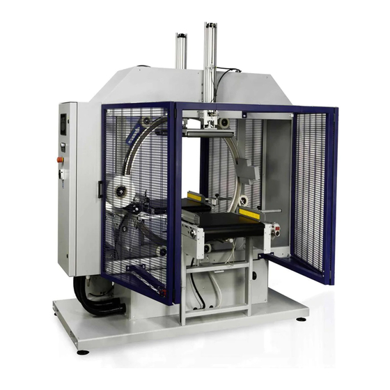
3. TECHNICAL INFORMATION 3.1. MACHINE GENERAL DESCRIPTION The above-mentioned machine is a rotary ring wrapping machine intended to spiral wrap products of varying size and shape. Stretch film spools commonly available on the market are used for wrapping. Wrapping is performed by combining film spool rotation with the horizontal movement of the product. The operator must place the product on the machine and start the cycle using the foot pedal control, subsequent wrapping, length wrapping, film fastening and cutting operations are automatic. - Page 21 The illustration shows, for information purposes only, the machine models, and the legend lists the parts. Legend: 1. Base: is the main structure of the machine. 2. Control panel: it allows activating machine functions. 3. Belt conveyor: system used to transport the product to be wrapped, consisting of motorised roller conveyors. 4.
-
Page 22: Machine Models Description
During the operating stages just one operator is necessary to perform the product feeding, cycle start and wrapped product unloading operations. According to the different operating requirements, this machine can be supplied in different models and configurations. Machine Spool Orbit 4 Orbit 6 Orbit 9 Orbit 9 Orbit 12 125 / 250 3.2. - Page 23 “Total” wrapping After the product has been placed on the infeed conveyor, press the button “Start” on the control panel to enable the automatism and press the foot pedal control to start the work cycle. Phase 1 The conveyor starts and moves the product towards the rotary ring.
- Page 24 Phase 2 When the “head and tail wraps” count is completed, the conveyor restarts and product length wrapping begins. The product moves forward and engages photocell (B2), the outfeed presser lowers on the product while the machine continues to wrap the product. Important The overlapping of film wraps is defined by the conveyor speed, the slewing ring speed...
- Page 25 Phase 4 When the “head and tail wraps” count is completed, the rotary ring stops while the clamp blocks and cuts the film as it recedes. The outfeed conveyor restarts. The product disengages the photocell (B2), the outfeed presser rises and the “conveyor unloading” timer starts. When timer count is over, the conveyor stops and the totally wrapped product can be removed from the machine.
- Page 26 When the timer count is over, the roller conveyor stops, the rotary rings starts and activates the “head and tail wraps” count; the head of the product is wrapped. At the last wrap of the rotary ring, the clamp comes out to hook the film;...
- Page 27 Phase 3 The product moves forward disengaging photocell (B1), the infeed presser rises and the ring starts rotating. After one revolution, conveyors turn on and the “tail positioning” timer starts. When the timer count is over, the outfeed conveyor stops, the “head and tail wraps” count starts; the tail part of the product is wrapped while the clamp advances to hook the film at the last wrap of the rotary ring.
- Page 28 “Total” and “central bands” wrapping After the product has been placed on the infeed conveyor, press the button “Start” on the control panel to enable the automatism and press the foot pedal control to start the work cycle. Phase 1 The conveyor starts and moves the product towards the rotary ring.
- Page 29 Phase 2 Once the “reinforcing wrappings” count is over, the conveyor restarts product wrapped longitudinally. The product moves forward and engages photocell (B2), the outfeed presser lowers on the product while the machine continues to wrap the product. Important The overlapping of film wraps is defined by the conveyor speed, the slewing ring speed as well as by the film width.
- Page 30 Phase 4 The product moves forward disengaging photocell (B1), the infeed presser rises, the “tail positioning” timer starts. After timer count is over, the outfeed conveyor stops and the “reinforcing wraps” count is started; the tail part of the product is wrapped while the clamp advances to hook the film at the last wrap of the rotary ring.
- Page 31 “Head-tail” and “central bands” wrapping After the product has been placed on the infeed conveyor, press the button “Start” on the control panel to enable the automatism and press the foot pedal control to start the work cycle. Phase 1 The conveyor starts and moves the product towards the rotary ring.
- Page 32 Phase 2 Infeed and outfeed conveyors start. The product moves forward and engages photocell (B2). The outfeed presser lowers on the product. Phase 3 The “central bands” timer starts; at count completed, the conveyor stops, the rotary ring starts and counts the “reinforcing wrappings”...
- Page 33 Phase 4 The product moves forward disengaging photocell (B1), the infeed presser rises and the ring starts rotating. After one revolution, conveyors turn on and the “tail positioning” timer starts. When the timer count is over, the outfeed conveyor stops, the “head and tail wraps” count starts; the tail part of the product is wrapped while the clamp advances to hook the film at the last wrap of the rotary ring.
-
Page 34: Safety Device Description
3.3. SAFETY DEVICE DESCRIPTION The figure shows the position of the devices on the machine. 1. Main switch It cuts off the power supply to the machine and can be padlocked to prevent use by unauthorised people. 2. Emergency buttons When pressed they immediately stop the machine in emergency conditions. - Page 35 1. General release solenoid valve: It closes compressed air mains supply when the machine is not powered. 2. Bi-stable solenoid valve: It stops all pneumatically driven movements when electricity is disconnected, both in case of a blackout and when the emergency button is pressed. 3.
-
Page 36: Description Of Electrical Devices
3.4. DESCRIPTION OF ELECTRICAL DEVICES The figure shows the position of the devices on the machine. 1. Photocell (B1) It detects product presence on the infeed conveyor. 2. Photocell (B2) It detects product presence on the outfeed conveyor. 3. Timing sensor (SQ3) It detects the rotary ring in the start cycle position (machine set up). -
Page 37: Description Of Pneumatic Devices
3.5. DESCRIPTION OF PNEUMATIC DEVICES The figure shows the position of the devices on the machine. 1. Tap To eliminate the pneumatic pressure inside the machine. 2. Pressure regulator with filter and pressure gauge To adjust the general pressure of the pneumatic system. Turn the knob to change the pressure values indicated on the pressure gauge. -
Page 38: Description Of Accessories On Request
3.6. DESCRIPTION OF ACCESSORIES ON REQUEST Spool carriage with 50 mm internal diameter (Orbit 4 and 6) Infeed and outfeed belt conveyor unit (length 1500 mm and 3000 mm) Side guide unit (roller or skid guides) for standard conveyors (length 600 mm) -
Page 39: Product Dimensions
For best quality results, the product cross section should be as close as possible to the machine diameter. For products that intersect the hatched areas, contact the Manufacturer. Machine Spool Minimum size of product that can be processed (mm) Orbit 4 50 x 50 x 450 Orbit 6 70 x 70 x 450 Orbit 9... -
Page 40: Machine Dimensions
3.7.2. MACHINE DIMENSIONS (standard L = 600 mm for Orbit 4-6-9, L = 850 mm for Orbit 12) Orbit 4 Orbit 6 Orbit 9 Orbit 12 1985 1983 2162 2243 1258 1462 1920 2348 1350 1755 2182 2699 min. H’... -
Page 41: Machine Dimensions With Conveyors
3.7.3. MACHINE DIMENSIONS WITH CONVEYORS (optionals 1500 mm long) Orbit 4 Orbit 6 Orbit 9 Orbit 12 3187 3187 3316 3348 1258 1489 1920 2348 1350 1755 2182 2699 min. H’ max. 1100 TECHNICAL INFORMATION... -
Page 42: Film Technical Features
3.7.4. FILM TECHNICAL FEATURES Orbit 4 Orbit 6 Orbit 9 Orbit 12 D optional 50/125 250 (opt.) Thickness μm 17-50 TECHNICAL INFORMATION... -
Page 43: Solenoid Valves Technical Features
3.7.5. SOLENOID VALVES TECHNICAL FEATURES Solenoid valve Y0: it closes compressed air supply when power is disconnected. Solenoid valve Y1: it controls clamp opening and closing. Solenoid valve Y2: it controls infeed presser up and down movement. Solenoid valve Y3: it controls outfeed presser up and down movement. -
Page 44: Noise Level
3.8. NOISE LEVEL During the operation the machine reaches the noise levels indicated in the table. Acoustic power detection carried out in operating conditions according to the following standards: ISO 3746-79 ISO/cd 11202-1997 Caution - warning Prolonged exposure above 80 dB (A) can be harmful. Obligation The use of appropriate protection systems is recommended (earmuffs, ear plugs, etc.). -
Page 45: Installation Environment Characteristics
3.9. INSTALLATION ENVIRONMENT CHARACTERISTICS The place where the machine is to be installed must be carefully selected taking into account the environment conditions in order to have correct and risk-free operating conditions. Therefore we suggest to take into account the following prerequisites: Ambient temperature between +0°C and 40°C. -
Page 46: Information On Handling And Installation
4. INFORMATION ON HANDLING AND INSTALLATION 4.1. RECOMMENDATIONS FOR HANDLING AND LOADING Before performing any operation, the authorised operator must make sure to have understood the “Instructions for use”. Carefully read the “Instructions for use” specified in the manual and those applied directly to the machine and/or the package. - Page 47 Package in crate Standard L = 600 mm L = 850 (Orbit 12) Optional L = 1500 mm INFORMATION ON HANDLING AND INSTALLATION...
-
Page 48: Transport And Handling
4.3. TRANSPORT AND HANDLING Transport, also according to the destination, can be performed with different vehicles. The diagram represents the most used solutions. During transport, in order to avoid sudden movements, adequately anchor the machine to the vehicle. Important For further transportations, recreate the initial packaging conditions for transport and handling. INFORMATION ON HANDLING AND INSTALLATION... -
Page 49: Handling And Lifting
4.4. HANDLING AND LIFTING The machine can be moved with a forklift truck with suitable load capacity by inserting the forks in the points indicated directly on the machine. INFORMATION ON HANDLING AND INSTALLATION... -
Page 50: Installation Of The Machine
4.5. INSTALLATION OF THE MACHINE Unpacking 1. Take off the cover cloth. 2. Remove the fasteners from all components (plastic strap or wooden anchors). 3. Visually check the material making sure it is not damaged in any way. Important You are advised to keep the packaging material. How to carry out the standard assembly Danger - warning Authorised technical service personnel must perform installation and assembly operations. -
Page 51: Conveyors Assembly
6. Use the support feet to level the machine. 7. The machine can be fastened to the floor, if required, by drilling holes in the walls prepared on the support feet. 4.5.1. CONVEYORS ASSEMBLY (length 1500 mm / 850 mm) 1. - Page 52 6. Connect the pneumatic tubes (M) to the cylinder of the clamp unit after conveyor assembly (see following pages). Important Remember that the tube that controls the exit of the clamp is marked with a “6” while the one that controls its return is marked with a “5”.
- Page 53 7. Connect the infeed conveyor to the base and tighten screws (C). Important Remember that the adhesive arrows on the conveyors indicate the normal operating direction. Caution - warning During the operation pay attention not to damage the clamp unit. INFORMATION ON HANDLING AND INSTALLATION...
- Page 54 8. Use the support feet to level the machine. INFORMATION ON HANDLING AND INSTALLATION...
- Page 55 9. Connect the photocell (L) cable (H). 10. Insert plug (A) into socket (B). 11. Fasten the electrical cable to the machine using self-locking ties. 12. Repeat the same operations for the outfeed conveyor. INFORMATION ON HANDLING AND INSTALLATION...
-
Page 56: Presser Unit Installation
4.5.2. PRESSER UNIT INSTALLATION (only Orbit 9 - 12) The machine arrives with the pressers to be positioned. Proceed as follows to install the pressers correctly. 1. Fix the presser to the structure in correspondence of the 4 screws (B). 2. -
Page 57: Pneumatic Connection
4.7. PNEUMATIC CONNECTION 1. Insert a flexible hose in the end of the hose barb fitting and fasten it with a metallic screw clamp (A). 2. Check that the valve (B) is in the “OPEN” position. 3. Activate the supply line pressure. 4. -
Page 58: Electrical Connection
4.8. ELECTRICAL CONNECTION Standard machines work with the following mains voltage values: Standard machines work with the following mains voltage values: Proceed as follows for the electrical connection. 1. Check that the line voltage (V) and frequency (Hz) correspond to those of the machine (see identification plate and wiring diagram). -
Page 59: Information On Adjustments
Pay attention to the safety warnings, do not misuse the machine and assess the possible residual risks. 5.2. INFEED AND OUTFEED CONVEYOR HEIGHT ADJUSTMENTS Adjustments of conveyor height (Orbit 4-6-9) According to the product to be wrapped, adjust the infeed and outfeed conveyor height. - Page 60 Adjustments of conveyor height (Orbit 12) According to the product to be wrapped, adjust the infeed and outfeed conveyor height. 1. Loosen knobs (A). 2. Position the conveyors checking the height on the graduated scale (B). 3. Tighten knobs (A). Important Use a spirit level to adjust conveyor horizontality and coplanarity.
-
Page 61: Roller Or Skid Guides Adjustments (Optional)
5.3. ROLLER OR SKID GUIDES ADJUSTMENTS (OPTIONAL) Width 1. Insert guides on the side of the conveyors in positions 1. 2. Fix the guides with 2 M8 screws. 3. According to the product to be wrapped, adjust the guides by regulating knobs (A). 4. - Page 62 When wrapping very wide products, guide supports must be moved after loosening the handles (B). Important Remember that in case of products wider than the conveyors, the position of the photocells must also be adjusted. INFORMATION ON ADJUSTMENTS...
- Page 63 Guide position 1. Adjust the position of the guides according to the product to be wrapped, after loosening the screws (A). 2. Check that the guides do not engage the photocells. Caution - warning Keep the guides on the infeed and outfeed conveyors as close to the rotary ring as possible; for extremely short products, prevent the pressers from lowering onto the guides.
-
Page 64: Position Of Photocells
5.4. POSITION OF PHOTOCELLS 1. Should the width of the product be greater than the conveyors, it is necessary to move the position of photocells (A) and of the reflectors (B) by acting on screws (C) without removing them. Important The photocells and reflectors can be moved along the conveyors. -
Page 65: Pressers Adjustment
5.5. PRESSERS ADJUSTMENT Height position When processing round and very high products, move the pressers in top position: 2. Disassemble the supports by removing screws (B). 3. Reinstall them to the desired position. Caution - warning Between pressers in top position and the product there must always be space. INFORMATION ON ADJUSTMENTS... - Page 66 The pressers, when in the low position, must not rest against the conveyor but must keep a distance of 10/15 mm. Check the position, operate the corresponding solenoid valve (Y2/Y3) manually with a screwdriver to lower the presser. Important When processing very heigh products, the roller (C) of both pressers could interfere with the rotary ring. In this case, you must disassemble the supports (D) and mount them back into the farthest holes from the rotary ring.
-
Page 67: Presser Pressure Adjustment
5.6. PRESSER PRESSURE ADJUSTMENT 1. Based on the type of product, adjust the pressure using the knob (A) so that the pressers securely hold the product without deforming it. Pressure can be read on the pressure gauge (B). INFORMATION ON ADJUSTMENTS... -
Page 68: Adjustment Of Spool Carriage Roller Clutch
5. Adjust the clutch on the spool carriage roller using the knob (E); turn clockwise to increase the braking effect. 6. Close the door and press the reset push-button. 7. Press the “Home” (F) key to return to the main page and to set up the machine. Orbit 4-6-9 Orbit 6-9-12 with dandy roller group INFORMATION ON ADJUSTMENTS... -
Page 69: Wrapping Tension Adjustment
7. Press the “Home” (F) key to return to the main page and to set up the machine. Caution - warning Do not excessively increase the braking effect. Orbit 4 - 6 - 9 Orbit 6 – 9 – 12 with dancer roller group INFORMATION ON ADJUSTMENTS... -
Page 70: Information About The Use
6. INFORMATION ABOUT THE USE 6.1. RECOMMENDATIONS FOR OPERATION AND USE When using the machine for the first time, the operator must read the manual and identify the control functions and simulate some operations, especially machine start and stop. Make sure that all safety devices are properly installed and efficient. Only carry out the operations foreseen by the Manufacturer and do not tamper with any device to obtain different performance levels. -
Page 71: Description Of The Controls
6.2. DESCRIPTION OF THE CONTROLS 1. Main switch It turns the power supply on and off. Position 0 (OFF) indicates that the machine is not powered. Position 1 (ON) indicates that the machine is powered. 2. Emergency button It immediately cuts off the power supply in emergency situations stopping the machine. Important After the emergency button activation, you must press the reset button to enable the automatic cycle. -
Page 72: Description Of Control Panel
6.3. DESCRIPTION OF CONTROL PANEL The control panel is a device that allows you to set the working parameters and to check all the operating conditions of the machine. It has a display (1) that allows you to activate the various functions by simply "touching" the images and texts that appear on it. -
Page 73: Using The Panel
6.3.1. USING THE PANEL Upon switching on the machine the introduction page will be displayed containing: Manufacturer’s identification. Press the “Reset” button. When machine is ready, the main page is displayed. Press the “START” button to enable the automatism and accept the recipe displayed, or touch the (A) key to display the recipe list. -
Page 74: Main Page
6.3.2. MAIN PAGE The page displays the wrapping values currently in use and gives access the other pages. A) It displays the name of the recipe in use. B) Key to access the wrapping number setting (See "Cycle parameters setting"). C) Main display, shows the wrapping cycle selected in the active recipe (See "Cycle parameters setting"). -
Page 75: Operator And Password Change
4. Enter the password (1111) assigned to machine manager (B1). B1) Machine manager (head of department). B2) Assistance Service (dealer). B3) Software administrator (Robopac). Once the operator is changed and confirmed the (H) icon on the main page will become that of the confirmed operator. -
Page 76: Default Password Reset
3. If it is correct, confirm by touching key (F), confirm again in the pop-up window by touching key (G). 6.3.4. DEFAULT PASSWORD RESET If you need to reset the default password in case you have forgotten the set password or for other reasons, proceed as indicated: 1. -
Page 77: General Parameter Settings
6.3.5. GENERAL PARAMETER SETTINGS From the main page, touch key (C) to access the "General parameters" page. Touch key (1) to access “Production counters”. Touch key (2) to access "H.M.I. Enabling" (See “Software settings and displays”). INFORMATION ABOUT THE USE... - Page 78 Touch key (3) to access “Password login” (See “Operator change”). Touch key (4) to access the password change (See “Password change”). Touch key (5) to access the "Product loading and unloading" page. INFORMATION ABOUT THE USE...
-
Page 79: Software Settings And Displays
6.3.6. SOFTWARE SETTINGS AND DISPLAYS From the main page, touch key (C) to access the "General parameters" page. Touch key (2) to access the "H.M.I. Enabling" page. INFORMATION ABOUT THE USE... - Page 80 2.1) Set the display light brightness. 2.2) Display information about software version. 2.3) Set the date and time. INFORMATION ABOUT THE USE...
- Page 81 2.4) Display information on machine status for assistance purposes. 2.5) Display a summary of the last alarms tripped on the machine. 2.6) Enable / disable the key sound. Change the various parameters and confirm with “ESC” (A). These keys are only displayed if the machine manager accesses software...
-
Page 82: Date And Time Setting
6.3.7. DATE AND TIME SETTING Display the main page (see “Description of control panel”-“Main page”). Touch key (C) to access the general parameters page. Touch key (3) and access with the password as machine manager (see “Description of control panel”- “Operator and password change”). -
Page 83: Description Of Control Panel Manual Controls
6.3.8. DESCRIPTION OF CONTROL PANEL MANUAL CONTROLS Manual controls are to be used to individually operate the machine moving parts, in case of service or check before the automatic cycle start- By touching the key (A) from the main page, you can access the manual movements. - Page 84 Rotation of the slewing ring/spool change. Incoming product presser upstroke/downstroke. Outgoing product presser upstroke/downstroke. Product infeed/outfeed conveyor forward/backward. Rotary cutting unit exit/return. Clamp exit/return. Sealer/block on the striker plate upstroke/downstroke. Exit/return of the cutting blade. Opening/closing of the guides at product infeed.
-
Page 85: Setting Modification Mode
6.4. SETTING MODIFICATION MODE Texts and values editing. Progressive adjustment of values. Important The performed modifications are applied immediately and are stored automatically. 6.4.1. TEXTS AND VALUES EDITING The keypad is displayed each time the editable or programmable functions are enabled. Type the requested value or name and confirm by pressing “ENTER”... -
Page 86: Copy Recipes" Function
6.4.3. “COPY RECIPES” FUNCTION 1. Display the main page (see “Main page”). 2. Press key (A) to display the recipe list. 3. Press key (B) to access the "Copy Recipes" page. 4. Press key (C) to copy recipes from the control panel to the SD card (supported by a PC). -
Page 87: Cycle Parameter Setting (Recipe Composition)
6.5. CYCLE PARAMETER SETTING (RECIPE COMPOSITION) 1. Display the main page (see “Description of control panel”-“Main page”). 2. Touch key (C) to access the general parameters page. 3. Touch key (3) and access with the password as machine manager (see “Description of control panel”- “Operator and password change”). - Page 88 6. Press keys “+” and “-” to increase or decrease the parameter value. graphic represents the value set for admitted values (see “Setting modification mode”). 7. Touch the key (Z) to return to the previously displayed page. INFORMATION ABOUT THE USE...
- Page 89 The parameters of the wrapping cycle are the following: B1) Number of wrappings (varying from 1 to 9). It allows you to set the number of additional wraps to be carried out at the beginning of the wrapping cycle (product head). B2) Number of wrappings (varying from 1 to 9).
- Page 90 Product wrapping start time (head). It is the time that determines the position of wrapping start with respect to the product head. Rotary ring and conveyor speed function. Rotary ring speed function To increase or decrease rotary ring speed; this allows to speed up or slow down the process and to respectively decrease or increase film overlapping.
-
Page 91: Cycle Reset
M) Product wrapping end time (tail). It is the time that determines the position of wrapping end with respect to the tail of the product. Important To rename the recipe, tap key (P). Once the keypad is displayed, follow the instructions paragraph "Setting... -
Page 92: Machine Statuses
6.7. MACHINE STATUSES Machine isolated from the power supplies This machine status is requested to perform any intervention in dangerous areas or in their immediate surroundings. It is obtained in the following way: Main switch in pos. "0". Air inlet tap closed. Machine on This machine status is necessary to perform all those machine interventions that need power and pneumatic supply. - Page 93 Synchronisation of the rotary ring The machine does not operate and does not block the film in the clamp if the rotary ring is not synchronised. No matter what the position of the rotary ring is, when the START pedal is pressed, the machine will synchronise the rotary ring instead of starting the operations.
- Page 94 5. Insert the spool on the roller following the diagram in the figure. The hatching shows the adhesive side (internal or external) of the film. Unwind the film out of the protection ring. A) Spool carriage roller B) Roller with clutch C) Idler rollers D) Dancer roller INFORMATION ABOUT THE USE...
- Page 95 6. Adjust the clutch on the spool carriage roller using the knob (E); turn clockwise to increase the braking effect. 7. Close the door (D) and press the “Reset” button. 8. Press the “Home” (F) key to return to the main page and to set up the machine. INFORMATION ABOUT THE USE...
- Page 96 Film insertion in the clamp 1. Display the main page. 2. Check that the rotary ring is synchronised. 3. Touch button (B) to let the clamp (C) come out completely. Danger - warning Do not expose your hands to the cutting area. INFORMATION ABOUT THE USE...
- Page 97 4. Open the guard (B). 5. Manually unwind the film and let it pass, well stretched, under and against the clamp bar (C) and engage it onto the disc (D). 6. Close the guard (B). 7. Press the “Reset” button (E). INFORMATION ABOUT THE USE...
- Page 98 8. Press button (F) to retract the clamp, cutting and blocking the film. 9. By pressing the “Cycle start” button (Q) the machine completes the cycle and stops automatically. INFORMATION ABOUT THE USE...
-
Page 99: Cycle Start
6.10. CYCLE START 1. Make sure that the film is blocked in the clamp. 2. Make sure that the machine is set up. 3. Place the product to be wrapped on the infeed conveyor. 4. Select the recipe from the control panel (see 6.3. “Description of control panel” - “Use of the panel”). 5. - Page 100 Production end stop This situation occurs when the work shift or machine use is over or when the machine remains inactive or not attended for a certain period of time. 1. Turn main switch to pos. 0. Emergency stop Press the EMERGENCY button. Machine functions stop immediately.
-
Page 101: Maintenance Information
7. MAINTENANCE INFORMATION 7.1. RECOMMENDATIONS FOR MAINTENANCE Proper maintenance will allow a longer life span and constant compliance with safety requirements. Before performing any operation, the authorised operator must make sure to have understood the “Instructions for use”. Pay attention to the safety warnings, do not misuse the machine and assess the possible residual risks. Carry out the interventions with all the safety devices enabled and wear the required PPE. -
Page 102: Periodical Maintenance Intervals
7.2. PERIODICAL MAINTENANCE INTERVALS Important Keep the machine in maximum efficiency conditions and perform all the scheduled maintenance operations provided for by the Manufacturer. Proper maintenance will provide the best performance, a longer life span and constant compliance with safety requirements. Maintenance interval table Frequency Component... -
Page 103: Condensate Drainage
7.3. CONDENSATE DRAINAGE 1. Close the tap (A) and check the level of condensation in the container (B). 2. Unscrew, if necessary, the valve (C) to drain the condensation. 3. Push the valve (C) upwards until all condensation is let out. 4. -
Page 104: Rotary Ring Handling
7.5. ROTARY RING HANDLING The ring will always stop with spool synchronised; if manual spool carriage unit rotation is necessary proceed as follows. 1. Switch the machine off. 2. Release the motor brake by tightening the screw (A) completely; the spool carriage unit is now free to rotate. 3. -
Page 105: Rotary Ring Belt Adjustment
2. Act on screw (B) to achieve correct belt tension. 3. Tighten the reduction unit fastening screws (A) when adjustment is completed. Important To avoid transmission overload, do not excessively tighten the belt. Orbit 4-6 Orbit 9 Orbit 12 MAINTENANCE INFORMATION... -
Page 106: Infeed And Outfeed Conveyor Belt Adjustment
7.7. INFEED AND OUTFEED CONVEYOR BELT ADJUSTMENT 1. Loosen the fastening nuts. 2. Tighten the screws (A). 3. Tighten the nuts. Important Tensioning must be performed equally on both sides of the conveyor so as to maintain the belt centred during its movement. -
Page 107: Machine Cleaning
7.8. MACHINE CLEANING General cleaning of the machine is fundamental to guarantee its efficiency over time. The whole machine must be kept free from dust, dirt and foreign bodies. The chrome-plated shafts must be cleaned with a cloth and slightly lubricated with a cloth soaked in Vaseline oil. The parts in plastic material (1) must be cleaned with a slightly damp cloth;... -
Page 108: Fault Information
8. FAULT INFORMATION 8.1. SOME SUGGESTIONS ON OPERATION Following are some problems that might occur during operation and their solution. Problem Solution Film is too slacken during the wrapping operation Increase the braking effect of the roller with clutch. Film is too slacken during the wrapping operation Reduce the braking effect of the roller with clutch Film overlaps too little on the product Decrease conveyor speed... - Page 109 Code Problem Cause Solution The photocell detects that the Remove the product or align Product infeed photocell product is not in the correct the photocell with the alarm position or that the reflector is reflector. not properly aligned. The photocell detects that the Remove the product or align Product outfeed photocell product is not in the correct...
-
Page 110: Replacement Information
9. REPLACEMENT INFORMATION 9.1. RECOMMENDATIONS FOR REPLACING MACHINE PARTS Carry out the interventions with all the safety devices enabled and wear the required PPE. Do NOT carry out interventions that are not described in the manual but contact a Service Centre authorised by the manufacturer. -
Page 111: Recommended Spare Parts List
9.3. RECOMMENDED SPARE PARTS LIST List of the spare parts that wear easily and that should be always available to avoid long machine downtimes. Cutting blade. To order them, contact your local dealer and refer to the spare parts catalogue. Important Replace worn parts with original spare parts. -
Page 112: Annexes
Robopac S.p.A. will in no case be held responsible for any losses due to lack of production or injuries to persons or damage to things caused by malfunctions or forced downtime of the machine covered by the warranty. -
Page 113: Standard Machine Pneumatic Diagram
10.2. STANDARD MACHINE PNEUMATIC DIAGRAM Legend: A) Air treatment unit. B) Pressure regulator. C) Input/output pressure cylinder. D) Clamp cylinder. F) Pressure gauge. G) Flow regulator. ANNEXES... - Page 114 EC DECLARATION OF CONFORMITY (Annex II A DIR. 2006/42/EC) Robopac S.p.A. Via Fabrizio da Montebello, 81 - 47892 Gualdicciolo Republic of San Marino DECLARES THAT THE MACHINE COMPLIES WITH THE DIRECTIVES DIRECTIVE 2006/42/EC OF THE EUROPEAN PARLIAMENT AND OF THE COUNCIL of 17 May 2006 on machinery, and amending Directive 95/16/EC.
Need help?
Do you have a question about the ORBIT 4 and is the answer not in the manual?
Questions and answers