Advertisement
INSTRUCTION MANUAL
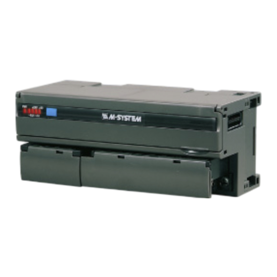
STRAIN GAUGE INPUT MODULE
(MECHATROLINK-I / -II, with monitor output, 2 points, isolated)
BEFORE USE ....
Thank you for choosing M-System. Before use, please check
contents of the package you received as outlined below.
If you have any problems or questions with the product,
please contact M-System's Sales Office or representatives.
■ PACKAGE INCLUDES:
Strain gauge input module .......................................... (1)
■ MODEL NO.
Confirm that the model number described on the product is
exactly what you ordered.
■ INSTRUCTION MANUAL
This manual describes necessary points of caution when
you use this product, including installation, connection and
basic maintenance procedures.
SEN TRONIC
POINTS OF CAUTION
■ CONFORMITY WITH EU DIRECTIVE
• Use MECHATROLINK-II network cable with core (Yasu-
kawa Controls Model JEPEC-W6003-x-E) or equivalent
for the network.
• Be sure to earth FG terminal.
• The actual installation environments such as panel con-
figurations, connected devices and connected wires may
affect the protection level of this unit when it is integrated
in a panel system. The user may have to review the CE
requirements in regard to the whole system and employ
additional protective measures to ensure CE conformity.
■ POWER INPUT RATING & OPERATIONAL RANGE
• Locate the power input rating marked on the product and
confirm its operational range as indicated below:
24V DC rating: 24V ±10%, approx. 130mA
■ GENERAL PRECAUTIONS
• Before you remove the unit or mount it, turn off the power
supply and input signal for safety.
■ ENVIRONMENT
• Indoor use
• When heavy dust or metal particles are present in the air,
install the unit inside proper housing with sufficient ven-
tilation.
• Do not install the unit where it is subjected to continuous
vibration. Do not subject the unit to physical impact.
• Environmental temperature must be within 0 to 55°C (32
to 131°F) with relative humidity within 30 to 90% RH in
order to ensure adequate life span and operation.
■ WIRING
• Do not install cables close to noise sources (relay drive
cable, high frequency line, etc.).
• Do not bind these cables together with those in which
noises are present. Do not install them in the same duct.
■ AND ....
• The unit is designed to function as soon as power is sup-
plied, however, a warm up for 10 minutes is required for
satisfying complete performance described in the data
sheet.
056 222 38 18
mailbox@sentronic.com
AG
R7ML-LC2
R7ML-LC2
MODEL
EM-7805-AX
www.sentronic.com
P. 1 / 10
Advertisement
Table of Contents

Subscribe to Our Youtube Channel
Related Manuals for M-system R7ML-LC2-R


Summary of Contents for M-system R7ML-LC2-R
- Page 1 MODEL (MECHATROLINK-I / -II, with monitor output, 2 points, isolated) BEFORE USE ..POINTS OF CAUTION Thank you for choosing M-System. Before use, please check ■ CONFORMITY WITH EU DIRECTIVE contents of the package you received as outlined below. • Use MECHATROLINK-II network cable with core (Yasu-...
-
Page 2: Component Identification
R7ML-LC2 COMPONENT IDENTIFICATION FRONT VIEW MECHATROLINK Setting Rotary SW Operating Mode Setting DIP SW (SW1) Station Address Setting PC Configurator Jack Rotary SW Input Status Indicator LED Status Indicator LED MECHATROLINK Connector 1 2 3 4 5 6 7 8 0 1 2 3 4 5 6 7 8 9 A B C D E F CNFG. - Page 3 R7ML-LC2 ■ STATUS INDICATOR LED • Excitation Voltage (SW1-8) COLOR EXPLANATION SW1-8 Excitation Voltage Green Turns on when the internal 5V is supplied 5 V (*) normally. 2.5 V Green Turns on in normal communications condi- tions. ■ INPUT STATUS INDICATOR LED Turns on in no communication or setting Each input status indicator LED turns ON when: error.
-
Page 4: External Dimensions
R7ML-LC2 EXTERNAL DIMENSIONS unit: mm (inch) 3 (.12) 115 (4.53) 17 (.66) 54 (2.13) DIN RAIL 35mm wide 10 11 12 13 15 16 17 18 30 (1.18) [5 (.20)] 75 (2.95) 6 (.24) 6 (.24) 7–M3 SCREW 18–M3 SCREW TERMINALS for POWER TERMINALS for I/O CONNECTION DIAGRAM... -
Page 5: Wiring Instructions
R7ML-LC2 WIRING INSTRUCTIONS ■ SCREW TERMINAL Torque: 0.5 N·m ■ SOLDERLESS TERMINAL mm (inch) Refer to the drawing below for recommended ring tongue terminal size. Spade tongue type is also applicable. Solder- less terminal: Applicable wire size: 0.25 to 1.65 mm (AWG 22 to 16) Recommended manufacturer: Japan Solderless Terminal MFG. Co., Ltd, Nichifu Co., Ltd 3.3 (.13) max mm (inch) MECHATROLINK CONNECTION MECHATROLINK CONNECTION Master Slave Slave... - Page 6 R7ML-LC2 MECHATROLINK RELATED COMMANDS Related commands are as follows. Command of MECHATROLINK has a two-layer structure, which is composed of Data Link Layer (upper layer) and Application Layer (lower layer). All the Application Layer Commands are located in lower layer of Data Link Layer (CDRW). COMMAND NAME COMMAND (hexadecimal) DESCRIPTION Data Link Layer Command Product type reading CDRW Data transmission Application Layer Command Invalid ID_RD Product information reading CONNECT Communication start with master DISCONNECT Communication stop with master DATA_RWA I/O data update ■ DATA LINK LAYER COMMAND •...
- Page 7 R7ML-LC2 ■ APPLICATION LAYER COMMAND Application Layer Command is located in lower layer of Data Link Layer Command (CDRW). Following tables are details on bytes 5 through 31 dependent upon Application Layer Command. Note : At 17 bytes mode, bytes dependant upon Application Layer Command are to be 5 through 17. • NOP (00H) Command Data Format 0, which indicates invalid command, is sent to the master Byte COMMAND (hexadecimal) RESPONSE (hexadecimal) REMARKS 5 – 31 Invalid • ID_RD (03) Command Data Format Reads product information. (max. 8 bytes at a time) Repeat reading multiple times in order to read out all the data. Byte COMMAND (hexadecimal) RESPONSE (hexadecimal) REMARKS...
- Page 8 R7ML-LC2 • Discrete Output Unit Byte COMMAND (hexadecimal) RESPONSE (hexadecimal) REMARKS Discrete output data low 8 bit Echo back of set value at command area Discrete output data high 8 bit Echo back of set value at command area 7 – 12 Unused Discrete output data of extension Discrete input data of extension module low 8 module low 8 bit bit or echo back of set value at command area Discrete output data of extension Discrete input data of extension module high 8...
- Page 9 R7ML-LC2 • LC2 Byte COMMAND (hexadecimal) RESPONSE (hexadecimal) REMARKS Input 0 set data low 8 bit Input 0 low 8 bit or echo back of set value at command area Input 0 set data high 8 bit Input 0 high 8 bit or echo back of set value at command area Input 1 set data low 8 bit Input 1 low 8 bit or echo back of set value at...
- Page 10 R7ML-LC2 ■ AUTOMATIC ZERO CORRECTION Set the offset input value. Perform automatic zero correction setting after Zero/Span adjustments. The procedures are as follows. 1) Apply desired offset input value to the sensor. 2) Set “1” to Automatic zero correction bit. When the offset is completed, LED0 for Input 0 or LED8 for Input 1 turns on. 3) After checking the LED, set “0” to Automatic zero correction bit. ■ ZERO ADJUSTMENT Adjust input zero point. The procedures are as follows. 1) Apply 0% load to the sensor. 2) Set “1” to Zero adjustment bit. When the adjustment is completed, LED1 for Input 0 or LED9 for Input 1 turns on. 3) After checking the LED, set “0” to Zero adjustment bit. ■ SPAN ADJUSTMENT (with actual load) Adjust input span point with the actual load. The procedures are as follows. 1) Apply actual 100% load to the sensor. 2) Set “1” to Span adjustment bit. When the adjustment is completed, LED2 for Input 0 or LED10 for Input 1 turns on. 3) After checking the LED, set “0” to Span adjustment bit. ■ LOAD COEFFICIENT Adjust input Span point by setting load coefficient without applying 100% actual load. The followings are an example of adjustment with 20 % load. 1) Apply 20% load of the actual load to the sensor. 2) Set 2000 (decimal) to Input set data area. 3) Set “1” to Span adjustment bit. When the adjustment is completed, LED2 for Input 0 or LED10 for Input 1 turns on.
Need help?
Do you have a question about the R7ML-LC2-R and is the answer not in the manual?
Questions and answers