Table of Contents
Advertisement
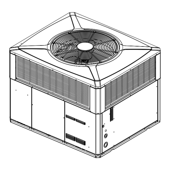
Installation and Operations Manual
Single Packaged Heat Pump, 16 SEER
Two Stage, Convertible, 2 – 5 Ton, R-410A
4WCZ6036B3000A
4WCZ6036B4000A
4WCZ6048B3000A
4WCZ6048B4000A
4WCZ6060B3000A
4WCZ6060B4000A
Only qualified personnel should install and service the equipment. The installation, starting up, and servicing of heating, ventilating, and air-conditioning
equipment can be hazardous and requires specific knowledge and training. Improperly installed, adjusted or altered equipment by an unqualified person
could result in death or serious injury. When working on the equipment, observe all precautions in the literature and on the tags, stickers, and labels that
are attached to the equipment.
March 2023
S S A A F F E E T T Y Y W W A A R R N N I I N N G G
1 1 8 8 - - B B B B 3 3 5 5 D D 1 1 - - 1 1 6 6 B B - - E E N N
N N o o t t e e : : "Graphics in this document are for representation
only. Actual model may differ in appearance."
N N o o t t e e : : "Unit specific Service Facts available online."
Advertisement
Table of Contents

Related Manuals for Trane 4WCZ6036B3000A


Summary of Contents for Trane 4WCZ6036B3000A
- Page 1 Installation and Operations Manual Single Packaged Heat Pump, 16 SEER Two Stage, Convertible, 2 – 5 Ton, R-410A 4WCZ6036B3000A 4WCZ6036B4000A 4WCZ6048B3000A 4WCZ6048B4000A 4WCZ6060B3000A 4WCZ6060B4000A N N o o t t e e : : “Graphics in this document are for representation only.
- Page 2 SAFETY SECTION I I m m p p o o r r t t a a n n t t — This document contains a wiring W W A A R R N N I I N N G G diagram, a parts list, and service information.
-
Page 3: Table Of Contents
Table of Contents Introduction, Unit Inspection and Attaching Downflow Ductwork to Roof Specification ....... 4 Frame. -
Page 4: Introduction, Unit Inspection And Specification
Introduction, Unit Inspection and Specification Introduction 2. Check the unit’s nameplate to determine if the unit is correct for the intended application. The power Read this manual carefully before attempting to install, supply must be adequate for both the unit and all operate, or perform maintenance on this unit. -
Page 5: Product Specification
I I n n t t r r o o d d u u c c t t i i o o n n , , U U n n i i t t I I n n s s p p e e c c t t i i o o n n a a n n d d S S p p e e c c i i f f i i c c a a t t i i o o n n Product Specification Model 4WCZ6036*3... -
Page 6: Charging In Cooling Above 55°F Od
I I n n t t r r o o d d u u c c t t i i o o n n , , U U n n i i t t I I n n s s p p e e c c t t i i o o n n a a n n d d S S p p e e c c i i f f i i c c a a t t i i o o n n Charging in Cooling above R-410A Subcooling Charging Table 55°F OD Ambient... -
Page 7: Determine Unit Clearances
Determine Unit Clearances Figure 1. Space on Sides Requirements 2 - 3 TON Units 3.5 - 5 TON Units RECOMMENDED SERVICE CLEARANCE mm [Inches] W/ ECONOMIZER W/ ECONOMIZER BACK SIDE 305 [12] 762 [30] 305 [12] 762 [30] LEFT SIDE 762 [30] 914 [36] 914 [36]... - Page 8 D D e e t t e e r r m m i i n n e e U U n n i i t t C C l l e e a a r r a a n n c c e e s s Figure 2.
-
Page 9: Information
Review Location and Recommendation Information H H o o r r i i z z o o n n t t a a l l A A i i r r f f l l o o w w U U n n i i t t s s 3. -
Page 10: Unit Installation
Unit Installation N N o o t t e e : : The factory ships this unit for horizontal retardant material. Insulate any ductwork outside of installation. the structure with at least two (2) inches of insulation and weatherproof. There must be a weatherproof seal where the duct enters the Ground Level Installation structure. -
Page 11: Lifting And Rigging
U U n n i i t t I I n n s s t t a a l l l l a a t t i i o o n n Figure 4. Converting Horizontal to Down Airflow Lifting and Rigging stability before hoisting it to the installation location. -
Page 12: Rooftop Installation - Frame
U U n n i i t t I I n n s s t t a a l l l l a a t t i i o o n n Table 1. Vibration Isolators/Snow Feet Locations Note: The installation instructions indicate typical installation only, but actual installation may differ. Note: These views represent the base as viewed looking up from underneath the unit. - Page 13 U U n n i i t t I I n n s s t t a a l l l l a a t t i i o o n n 10. Flexible duct connectors must be of a flame given careful consideration when locating the duct retardant material.
- Page 14 U U n n i i t t I I n n s s t t a a l l l l a a t t i i o o n n Table 4. Typical Rooftop Horizontal Airflow Application with Frame Supply Air Return Air Roof Flashing...
-
Page 15: Ductwork Installation
U U n n i i t t I I n n s s t t a a l l l l a a t t i i o o n n Ductwork Installation transmission from the unit to the ducts. The flexible connection m m u u s s t t be indoors and made out of heavy Attaching Downflow Ductwork to Roof canvas. -
Page 16: Electrical Wiring
U U n n i i t t I I n n s s t t a a l l l l a a t t i i o o n n Table 6. Filter Sizes (field supplied filter rack) Table 7. - Page 17 U U n n i i t t I I n n s s t t a a l l l l a a t t i i o o n n NOTES: 1. FUSED DISCONNECT SIZE, POWER WIRING AND GROUNDING OF EQUIPMENT MUST COMPLY WITH CODES.
-
Page 18: Unit Startup
Unit Startup Pre-Start Quick Checklist O O p p e e r r a a t t i i n n g g P P r r e e s s s s u u r r e e C C h h e e c c k k s s After the unit has operated in the cooling mode for a ☐... -
Page 19: Sequence Of Operation
U U n n i i t t S S t t a a r r t t u u p p Sequence of Operation H H E E A A T T I I N N G G M M O O D D E E T T h h e e r r m m o o s s t t a a t t c c a a l l l l f f o o r r h h e e a a t t ( ( 2 2 - - s s t t a a g g e e t t h h e e r r m m o o s s t t a a t t ) ) G G e e n n e e r r a a l l C C a a l l l l f f o o r r 1 1 s s t t s s t t a a g g e e h h e e a a t t i i n n g g o o n n l l y y : :... - Page 20 U U n n i i t t S S t t a a r r t t u u p p D D e e m m a a n n d d D D e e f f r r o o s s t t O O p p e e r r a a t t i i o o n n delay options, and electric heat airflow adjustment.
-
Page 21: Final Installation Checklist
U U n n i i t t S S t t a a r r t t u u p p Final Installation Checklist N N o o t t e e : : It may be necessary to replace permanent filters annually if washing fails to clean the filter or if I I m m p p o o r r t t a a n n t t : : Perform a final unit inspection to be sure the filter shows signs of deterioration. - Page 22 U U n n i i t t S S t t a a r r t t u u p p 2. TST = Test (Shorting TEST_COMMON to this pin Sensor temp. = 19°F. speeds up all defrost board timings.) Measured Resistance = 46K ohms 3.
- Page 23 U U n n i i t t S S t t a a r r t t u u p p Table 12. Demand Defrost Control Checkout Table (continued) SYMPTOMS CHECKS YES/NO ACTIONS Check refrigerant circuits for balanced OD Temp. below 49°F.? OD Coil temp. distribution of refrigerant if OD coil is below 35°F.? "Delta"...
-
Page 24: Pressure Curves
U U n n i i t t S S t t a a r r t t u u p p Pressure Curves Figure 9. 4WCZ6036 Cooling Heating Cooling with Thermal Expansion Valve Heating with Thermal Expansion Valve INDOOR ENTERING WET BULB CURVES TOP TO BOTTOM INDOOR ENTERING DRY BULB CURVES TOP TO BOTTOM 71, 67, 63 AND 59 DEG F. - Page 25 U U n n i i t t S S t t a a r r t t u u p p Figure 10. 4WCZ6048 Cooling Heating Cooling with Thermal Expansion Valve Heating with Thermal Expansion Valve INDOOR ENTERING WET BULB CURVES TOP TO BOTTOM INDOOR ENTERING DRY BULB CURVES TOP TO BOTTOM 71, 67, 63 AND 59 DEG F.
- Page 26 U U n n i i t t S S t t a a r r t t u u p p Figure 11. 4WCZ4060 Cooling Heating 18-BB35D1-16B-EN...
-
Page 27: Indoor Fan Performance
U U n n i i t t S S t t a a r r t t u u p p Indoor Fan Performance EXTERNAL STATIC PRESSURE (IN.WG) Cooling CFM Horizontal [Downflow] 4WCZ6036 Motor Speed 350 CFM / [722] [745] [747] [744]... -
Page 28: Refrigerant Circuit
U U n n i i t t S S t t a a r r t t u u p p Refrigerant Circuit 18-BB35D1-16B-EN... -
Page 29: Troubleshooting Chart
U U n n i i t t S S t t a a r r t t u u p p Troubleshooting Chart P P - - P P R R I I M M A A R R Y Y C C A A U U S S E E S S / / S S - - S S E E C C O O N N D D A A R R Y Y C C A A U U S S E E S S SYSTEM FAULTS REFRIGERANT CIRCUIT Liquid Pressure too High... - Page 30 N N o o t t e e s s 18-BB35D1-16B-EN...
- Page 31 N N o o t t e e s s 18-BB35D1-16B-EN...
-
Page 32: Important Product Information
Service Phone ___________________________________________________________________ About Trane and American Standard Heating and Air Conditioning Trane and American Standard create comfortable, energy efficient indoor environments for residential applications. For more information, please visit www.trane.com or www.americanstandardair.com. The AHRI Certified mark indicates company participation in the AHRI Certification program. For verification of individual certified products, go to ahridirectory.org.
Need help?
Do you have a question about the 4WCZ6036B3000A and is the answer not in the manual?
Questions and answers