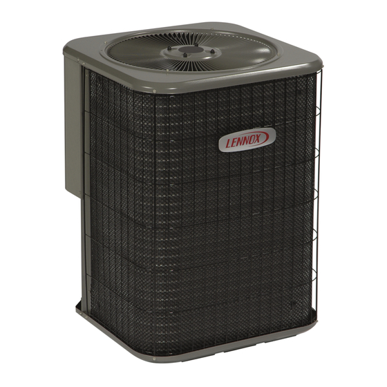
Trane 4TCY4024 Installer's Manual

Trane 4TCY4024 Installer's Manual

Single packaged, cooling w/ electric heat, 14 seer, convertible, 2 - 5 ton, r-410a
Hide thumbs Also See for 4TCY4024:

Advertisement

ALL phases of this installation must comply with NATIONAL, STATE AND LOCAL CODES
IMPORTANT — This Document is customer property. Please return to service information pack and give this Installer's Guide to the homeowner
upon completion of work.
WARNING:
WARNING
s
s
SAFETY HAZARD!
This information is for use by individuals having adequate
backgrounds of electrical and mechanical experience.
Any attempt to repair a central air conditioning product
may result in personal injury and/or property damage.
The manufacturer or seller cannot be responsible for the
interpretation of this information, nor can it assume any
liability in connection with its use.
Installer's Guide
Single Packaged, Cooling w/ Electric Heat,
14 SEER, Convertible, 2 - 5 Ton, R-410A
4TCY4024 through 4TCY4060
HAZARDOUS VOLTAGE - DISCONNECT POWER and DISCHARGE
18-EB26D1-16A-EN
CAPACITORS BEFORE SERVICING
WARNING
s
s
WARNING!
This product can expose you to chemicals including lead,
which are known to the State of California to cause cancer
and birth defects or other reproductive harm. For more
information go to www.P65Warnings.ca.gov
WARNING
s
s
SAFETY HAZARD!
Bodily injury can result from high voltage electrical com-
ponents, fast moving fans, and combustible gas. For
protection from these inherent hazards during installation
and service, the electrical supply must be disconnected
and the main gas valve must be turned off. If operating
checks must be performed with the unit operating, it is the
technician's responsibility to recognize these hazards and
proceed safely.

Advertisement

Table of Contents
loading
Need help?

Need help?

Do you have a question about the 4TCY4024 and is the answer not in the manual?

Questions and answers

Summary of Contents for Trane 4TCY4024

  • Page 1 ALL phases of this installation must comply with NATIONAL, STATE AND LOCAL CODES IMPORTANT — This Document is customer property. Please return to service information pack and give this Installer's Guide to the homeowner upon completion of work. 4TCY4024 through 4TCY4060 WARNING: HAZARDOUS VOLTAGE - DISCONNECT POWER and DISCHARGE...
  • Page 2: Safety Considerations

    Installer’s Guide Safety Considerations IMPORTANT: Read this entire manual before beginning installation procedures. WARNING NOTICE This product contains fiberglass wool insulation! Fiber- Warning and Cautions appear at appropriate glass dust and ceramic fibers are believed by the state of locations throughout this guide. Your personal California to cause cancer through inhalation.
  • Page 3: Table Of Contents

    4. If this unit is being installed on a curb, verify that the correct curb is provided with the unit. • 4TCY4024 through 4TCY4036 use BAYCURB050A. • 4TCY4042 through 4TCY4060 use BAYCURB051A. 5. If the unit is being hoisted, accessory kit BAYLIFT002A is recommended.
  • Page 4: Step 2-Determine Unit Clearances

    Step 2—Determine Unit Clearances Figures 1 to 6 show the unit critical dimensions. NOTE: The view labeled “Bottom Side” represents the Base as viewed looking up from underneath the unit. Figure 1. 4TCY4024 through 4TCY4036 (1 of 3) Page 4...
  • Page 5 Installer’s Guide Figure 2. 4TCY4024 through 4TCY4036 (2 of 3) Page 5...
  • Page 6 Installer’s Guide Figure 3. 4TCY4024 through 4TCY4036 (3 of 3) Page 6...
  • Page 7 Installer’s Guide NOTE: The view labeled “Bottom Side” represents the Base as viewed looking up from underneath the unit. Figure 4. 4TCY4042 through 4TCY4060 (1 of 3) Page 7...
  • Page 8 Installer’s Guide Figure 5. 4TCY4042 through 4TCY4060 (2 of 3) Page 8...
  • Page 9 Installer’s Guide Figure 6. 4TCY4042 through 4TCY4060 (3 of 3) Page 9...
  • Page 10: Step 3-Review Location & Recommendation Information

    Installer’s Guide Step 3—Review Location and Recommendation Information CAUTION Caution must be taken at all times to avoid personal injuries and/or damage to equipment. NOTE: The unit is shipped for horizontal installation. Horizontal Airflow Units Down Airflow Units 1. Location of the unit must allow service clearance around Location of the unit must allow service clearance around it to it to ensure adequate serviceability, maximum capacity, and ensure adequate serviceability, maximum capacity, and peak...
  • Page 11: Step 4-Unit Installation

    Installer’s Guide Step 4—Unit Installation NOTE: The factory ships this unit for horizontal installation. Rooftop Installation -- Curb Mounting Convert Horizontal Airflow to Down Airflow Ground Level Installation The factory ships the unit for horizontal airflow. Perform this To install the unit at ground level: procedure to convert it to down airflow: 1.
  • Page 12: Lifting And Rigging

    Installer’s Guide Figure 8. Converting Horizontal to Down Airflow Lifting and Rigging Placing the Unit on the Mounting Curb 1. The unit is designed with a perimeter drip lip that is lower than IMPORTANT: Do not lift the unit without test lifting for balance the unit base pan, see Figure 10, inset A, on page 14.
  • Page 13: Rooftop Installation -- Frame Mounting

    Installer’s Guide Small Cabinet Medium Cabinet *****018-036 *****042-060 NOTE: These views represent the base as viewed looking up from underneath the unit. IMPORTANT: Unit requires vibration isolator support in the general areas shown. Locate 3/4" thick vibration isolators on the bottom of the basepan as illustrated by black dots for ground level pad applications.
  • Page 14 Installer’s Guide IMPORTANT: To prevent damage to the sides and top of the unit when hoisting, use “spreader bars” as Base of unit shown in these illustrations. Drip lip on rest on top of perimeter of curb rails unit Spreader Bars Gasket Seal Drip Lip BAYLIFT002A...
  • Page 15 Installer’s Guide Supply Air Return Air Roof Flashing Channel Iron Center Support (Center Support required on Angle Iron Frame all Frame Applica- tions.) Figure 12. Typical Rooftop Horizontal Airflow Application with Frame Supply Air Return Air Roof Flashing Roof Flashing Angle Iron Frame Channel Iron Center Support (Center Support required on all...
  • Page 16: Ductwork Installation

    Installer’s Guide Ductwork Installation Attaching Downflow Ductwork to Roof Curb Supply and return air flanges are provided on the roof curb for easy UNIT EXTERIOR duct installation. All ductwork must be run and attached to the curb WEATHERPROOF THIS SEAM before the unit is set into place.
  • Page 17: Electrical Wiring

    Installer’s Guide Table 1. Filter Sizes (field supplied filter rack) NOMINAL FILTER FILTER UNIT RESISTANCE ("W.C.) SIZE(Sq Ft) 4*CY4024 2.67 0.08 4*CY4030 1000 3.33 0.08 4*CY4036 1200 0.08 4*CY4042 1400 4.67 0.08 4*CY4048 1600 5.33 0.08 4*CY4060 2000 6.67 0.08 *Filters must be installed in the return air system.
  • Page 18: Field Wiring Diagram

    Installer’s Guide Figure 20. Typical 4TCY4 Field Wiring Diagram Page 18...
  • Page 19: Control Wiring (Class Ii)

    Installer’s Guide Control Wiring (Class II)  Do the condenser fan and indoor blower turn free without Low voltage control wiring should not be run in conduit with power rubbing, and are they tight on the shafts? wiring unless Class 1 wire of proper voltage rating is used. Route ...
  • Page 20: Starting The Unit In Heating Mode

    Installer’s Guide Starting the Unit in Heating Mode NOTE: The indoor comfort control must be configured to provide NOTE: See the section on "Sequence of Operation" for a de- a “G” signal to energize the indoor fan relay (F) during the heating scription of the heating operating sequence.
  • Page 21: Service Maintenance

    Installer’s Guide Service Maintenance ECM Fan Motor Adjustments If the airflow needs to be increased or decreased, see the Cooling Season Airflow Table in the SERVICE FACTS. Information on chang- To keep the unit operating safely and efficiently, the manufacturer ing the speed of the blower motor is in the Blower Performance recommends that a qualified service technician check the entire Table.
  • Page 22 Installer’s Guide Notes: Page 22...
  • Page 23 Installer’s Guide Notes: Page 23...
  • Page 24 Service Phone_________________________________________________________________ About Trane and American Standard Heating and Air Conditioning Trane and American Standard create comfortable, energy efficient indoor environments for residential applications. For more information, please visit www.trane.com or www.americanstandardair.com The AHRI Certified mark indicates company participation in the AHRI Certification program. For verification of individual certified products, go to ahridirectory.org.

Table of Contents