Only qualified personnel should install and service the equipment. The installation, starting up, and servicing of heating, ventilating, and air-conditioning
equipment can be hazardous and requires specific knowledge and training. Improperly installed, adjusted or altered equipment by an unqualified person
could result in death or serious injury. When working on the equipment, observe all precautions in the literature and on the tags, stickers, and labels that
are attached to the equipment.
May 2023
S S A A F F E E T T Y Y W W A A R R N N I I N N G G
1 1 8 8 - - B B B B 4 4 1 1 D D 1 1 - - 1 1 C C - - E E N N
N N o o t t e e : : "Graphics in this document are for representation
only. Actual model may differ in appearance."
N N o o t t e e : : "Unit specific Service Facts available online."
Water-cooled heat pumps with scroll compressors for hot water production at very high temperatures heating capacity 37-550 kw (36 pages)
Summary of Contents for Trane 4WCC4036E1000B
Page 1
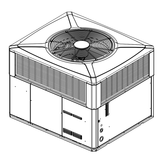
Installation and Operations Manual Single Packaged Heat Pump 13.4 SEER2 Convertible, 2 – 5 Ton 4WCC4024E1000A 4WCC4030E1000A 4WCC4036E1000B 4WCC4042E1000A 4WCC4048E1000A 4WCC4060E1000A N N o o t t e e : : “Graphics in this document are for representation only. Actual model may differ in appearance.”...
Page 2
SAFETY SECTION I I m m p p o o r r t t a a n n t t — This document contains a wiring W W A A R R N N I I N N G G diagram, a parts list, and service information.
Introduction, Unit Inspection and Specification Introduction 2. Check the unit’s nameplate to determine if the unit is correct for the intended application. The power Read this manual carefully before attempting to install, supply must be adequate for both the unit and all operate, or perform maintenance on this unit.
I I n n t t r r o o d d u u c c t t i i o o n n , , U U n n i i t t I I n n s s p p e e c c t t i i o o n n a a n n d d S S p p e e c c i i f f i i c c a a t t i i o o n n Product Specification MODEL 4WCC4024...
I I n n t t r r o o d d u u c c t t i i o o n n , , U U n n i i t t I I n n s s p p e e c c t t i i o o n n a a n n d d S S p p e e c c i i f f i i c c a a t t i i o o n n Charging in Cooling above pressure under the subcool value column, Add refrigerant to raise the pressure to match the table,...
Determine Unit Clearances Figure 1. Space on Sides Requirements 2 - 3 TON Units 3.5 - 5 TON Units RECOMMENDED SERVICE CLEARANCE mm [Inches] W/ ECONOMIZER W/ ECONOMIZER BACK SIDE 305 [12] 762 [30] 305 [12] 762 [30] LEFT SIDE 762 [30] 914 [36] 914 [36]...
Page 8
D D e e t t e e r r m m i i n n e e U U n n i i t t C C l l e e a a r r a a n n c c e e s s Figure 2.
Review Location and Recommendation Information 3. The field assembled Roof Mounting Curb H H o o r r i i z z o o n n t t a a l l A A i i r r f f l l o o w w U U n n i i t t s s (BAYCURB050A or BAYCURB051A) or a field fabricated curb should be in place before the unit is 1.
Unit Installation N N o o t t e e : : The factory ships this unit for horizontal insulation and weatherproof. There must be a installation. weatherproof seal where the duct enters the structure. Ground Level Installation 5. Do not expose the unit to direct roof water runoff. 6.
U U n n i i t t I I n n s s t t a a l l l l a a t t i i o o n n Figure 4. Converting Horizontal to Down Airflow Lifting and Rigging stability before hoisting it to the installation location.
U U n n i i t t I I n n s s t t a a l l l l a a t t i i o o n n Table 1. Vibration Isolators/Snow Feet Locations Note: The installation instructions indicate typical installation only, but actual installation may differ. Note: These views represent the base as viewed looking up from underneath the unit.
Page 13
U U n n i i t t I I n n s s t t a a l l l l a a t t i i o o n n 10. Flexible duct connectors must be of a flame given careful consideration when locating the duct retardant material.
Page 14
U U n n i i t t I I n n s s t t a a l l l l a a t t i i o o n n Table 4. Typical Rooftop Horizontal Airflow Application with Frame Supply Air Return Air Roof Flashing...
U U n n i i t t I I n n s s t t a a l l l l a a t t i i o o n n Ductwork Installation transmission from the unit to the ducts. The flexible connection m m u u s s t t be indoors and made out of heavy Attaching Downflow Ductwork to Roof canvas.
U U n n i i t t I I n n s s t t a a l l l l a a t t i i o o n n Table 6. Filter Sizes (field supplied filter rack) (3) pole contactor.
Page 17
U U n n i i t t I I n n s s t t a a l l l l a a t t i i o o n n Table 10. Field Wiring Diagram Notes: PAC K AG ED H EAT PU M P U N I T UNIT HEATER AREA UNIT CONTROL BOX Fused disconnect size, power wiring...
Unit Startup Pre-Start Quick Checklist O O p p e e r r a a t t i i n n g g P P r r e e s s s s u u r r e e C C h h e e c c k k s s After the unit has operated in the cooling mode for a ☐...
U U n n i i t t S S t t a a r r t t u u p p Sequence of Operation which starts the compressor and outdoor fan motor. The indoor thermostat contact T T S S H H - - 1 1 also provides G G e e n n e e r r a a l l power to "...
U U n n i i t t S S t t a a r r t t u u p p Final Installation Checklist If the unit has disposable-type filters, replace them with new filters of the same type and size. D D o o n n o o t t a a t t t t e e m m p p t t I I m m p p o o r r t t a a n n t t : : Perform a final unit inspection to be sure t t o o c c l l e e a a n n d d i i s s p p o o s s a a b b l l e e f f i i l l t t e e r r s s .
U U n n i i t t S S t t a a r r t t u u p p Defrost Control D D e e f f r r o o s s t t C C o o n n t t r r o o l l The demand defrost control measures heat pump outdoor ambient temperature with a sensor located outside the outdoor coil.
Page 22
U U n n i i t t S S t t a a r r t t u u p p Table 12. Defrost Control Thermistor Table Table 12. Defrost Control Thermistor Table (continued) THERMISTOR RESISTANCE Vo (Volts) TEMP °F TEMP °C 75.00 23.89...
Page 23
U U n n i i t t S S t t a a r r t t u u p p Table 14. LED Fault Codes the learning routine could complete in the same heating call. It is announced with a 5 flash and a 6 FAULT DEFROST CONTROL flash fault.
U U n n i i t t S S t t a a r r t t u u p p Pressure Curves Figure 8. 4WCC4024E1 Cooling Heating INDOOR ENTERING INDOOR ENTERING WET BULB CURVES DRY BULB CURVES TOP TO BOTTOM TOP TO BOTTOM 71, 67, 63 AND 59 DEG 80, 70, AND 60 DEG F.
Page 25
U U n n i i t t S S t t a a r r t t u u p p Figure 9. 4WCC4030E1 Cooling Heating INDOOR ENTERING INDOOR ENTERING WET BULB CURVES DRY BULB CURVES TOP TO BOTTOM TOP TO BOTTOM 71, 67, 63 AND 59 DEG 80, 70, AND 60 DEG F.
Page 26
U U n n i i t t S S t t a a r r t t u u p p Figure 10. 4WCC4036E1 Cooling Heating INDOOR ENTERING INDOOR ENTERING WET BULB CURVES DRY BULB CURVES TOP TO BOTTOM TOP TO BOTTOM 71, 67, 63 AND 59 DEG 80, 70, AND 60 DEG F.
Page 27
U U n n i i t t S S t t a a r r t t u u p p Figure 11. 4WCC4042E1 Cooling Heating INDOOR ENTERING INDOOR ENTERING WET BULB CURVES DRY BULB CURVES TOP TO BOTTOM TOP TO BOTTOM 71, 67, 63 AND 59 DEG 80, 70, AND 60 DEG F.
Page 28
U U n n i i t t S S t t a a r r t t u u p p Figure 12. 4WCC4048E1 Cooling Heating INDOOR ENTERING INDOOR ENTERING WET BULB CURVES DRY BULB CURVES TOP TO BOTTOM TOP TO BOTTOM 71, 67, 63 AND 59 DEG 80, 70, AND 60 DEG F.
Page 29
U U n n i i t t S S t t a a r r t t u u p p Figure 13. 4WCC4060E1 Cooling Heating INDOOR ENTERING INDOOR ENTERING WET BULB CURVES DRY BULB CURVES TOP TO BOTTOM TOP TO BOTTOM 71, 67, 63 AND 59 DEG 80, 70, AND 60 DEG F.
U U n n i i t t S S t t a a r r t t u u p p Indoor Fan Performance EXTERNAL STATIC PRESSURE (IN.WG) Horizontal Airflow [Down Airflow] 4WCC4024E1 Motor Speed Watts [63] [71] [77] [890] [811] [747]...
Page 31
U U n n i i t t S S t t a a r r t t u u p p EXTERNAL STATIC PRESSURE (IN.WG) Horizontal Airflow [Down Airflow] 4WCC4042E1 Motor Speed Watts [262] [268] [277] [288] [298] 1411 1355 1295 1239...
U U n n i i t t S S t t a a r r t t u u p p Refrigerant Circuit COOLING SWITCHOVER EXPANSION VALVE VALVE BULB EXPANSION VALVE BULB OUTDOOR INDOOR COIL COIL SCHRADER VALVE LO LPCO COIL EQUALIZER...
U U n n i i t t S S t t a a r r t t u u p p Troubleshooting Chart P P - - P P R R I I M M A A R R Y Y C C A A U U S S E E S S / / S S - - S S E E C C O O N N D D A A R R Y Y C C A A U U S S E E S S SYSTEM FAULTS REFRIGERANT CIRCUIT Liquid Pressure too High...
Service Phone ___________________________________________________________________ About Trane and American Standard Heating and Air Conditioning Trane and American Standard create comfortable, energy efficient indoor environments for residential applications. For more information, please visit www.trane.com or www.americanstandardair.com. The AHRI Certified mark indicates company participation in the AHRI Certification program. For verification of individual certified products, go to ahridirectory.org.