
Subscribe to Our Youtube Channel
Related Manuals for Measurement Computing E-DIO24


Summary of Contents for Measurement Computing E-DIO24
- Page 1 E-DIO24 Ethernet-based Digital I/O User's Guide Preliminar Document Revision 2A April 2016...
- Page 2 Other product and company names mentioned herein are trademarks or trade names of their respective companies. © 2016 Measurement Computing Corporation. All rights reserved. No part of this publication may be reproduced, stored in a retrieval system, or transmitted, in any form by any means, electronic, mechanical, by photocopying, recording, or otherwise without the prior written permission of Measurement Computing Corporation.
-
Page 3: Table Of Contents
What you will learn from this user's guide ......................5 Conventions in this user's guide ......................... 5 Where to find more information ......................... 5 Chapter 1 Introducing the E-DIO24 ........................6 Ethernet interface ..............................6 Functional block diagram ........................... 6 Chapter 2 Installing the E-DIO24 ........................... - Page 4 E-DIO24 User's Guide Ethernet connection .................................19 Network interface ................................19 Network factory default settings ............................19 Network security ................................19 LED displays and the factory reset button ......................20 Environmental ..............................20 Mechanical ............................... 20 Signal connector ............................... 21 Declaration of Conformity ........................22...
-
Page 5: Preface
Preface About this User's Guide What you will learn from this user's guide This user's guide describes the Measurement Computing E-DIO24 data acquisition device and lists device specifications. Conventions in this user's guide For more information Text presented in a box signifies additional information and helpful hints related to the subject matter you are reading. -
Page 6: Introducing The E-Dio24
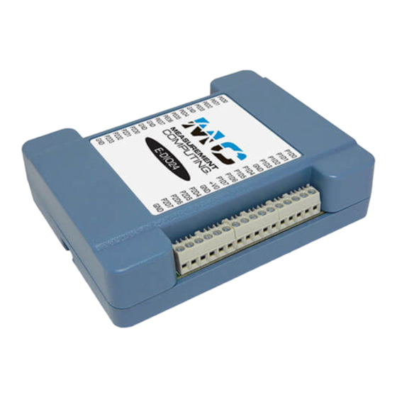
Chapter 1 Introducing the E-DIO24 The E-DIO24 is an Ethernet based digital I/O data acquisition device that is compatible with TCP (IPv4 only) and UDP network protocols. The E-DIO24 provides the following features: 24 individually-configurable digital I/O bits ... -
Page 7: Installing The E-Dio24
E-DIO24, and plug the AC adapter into an electrical outlet. LED turns on when 5 V power is supplied to the E-DIO24. If the voltage supply is less than 4.2 V Power or more than 5.6 V, the... -
Page 8: Configuring Network Settings
If the connected network does not have a DHCP server, the address stored in the default IP address is assigned. If the E-DIO24 is directly connected to a Windows PC or other host that supports link-local addressing, a link- local address is assigned. A link-local address is valid only for communications between the E-DIO24 and the PC to which it is connected. -
Page 9: Configuring The Network Router For Communication Across Networks
Installing the E-DIO24 Configuring the network router for communication across networks To communicate with the E-DIO24 from a computer connected to a different network – such as over the Internet – you must change the network configuration of the network router. -
Page 10: Chapter 3 Functional Details
LED status indicators Ethernet connector External power connector Factory reset button Screw terminals The E-DIO24 device screw terminals provide the following connections: 24 digital I/O connections ( P0D0 P2D7 One counter input (access with P2D7 ... -
Page 11: Led Status Indicators
This LED is off when the external power supply is not connected, or the input power is outside of the 4.2 V to 5.6 V voltage range of the external supply, causing a power fault. The E-DIO24 has an onboard voltage supervisory circuit that monitors the 5 V external power supply. ... -
Page 12: Signal Connections
Digital I/O The E-DIO24 has 24 DIO lines configured as three 8-bit ports – port 0, port 1, and port 2. Each bit is individually configurable for input or output. The digital I/O transfer rate is 5 kHz, maximum for software- paced operation on a local network. -
Page 13: Counter Input
E-DIO24 User's Guide Functional Details Figure 6. Pull-up/down jumper configurations, typical For more information about digital signal connections For general information about digital signal connections and digital I/O techniques, refer to the Guide to DAQ Signal Connections (available on our web site at www.mccdaq.com/pdfs/DAQ-Signal-Connections.pdf). -
Page 14: Mechanical Drawings
E-DIO24 User's Guide Functional Details Mechanical drawings Figure 7. E-DIO24 device circuit board dimensions... - Page 15 E-DIO24 User's Guide Functional Details Figure 8. E-DIO24 bottom enclosure dimensions...
-
Page 16: Din-Rail Compatible
E-DIO24 User's Guide Functional Details Figure 9. E-DIO24 top enclosure dimensions DIN-rail compatible The E-DIO24can be mounted on a DIN rail using the ACC-205 DIN-rail accessory kit. Refer to our website for more information. -
Page 17: Chapter 4 Specifications
Chapter 4 Specifications All specifications are subject to change without notice. Typical for 25 °C unless otherwise specified. Specifications in italic text are guaranteed by design. Digital input/output Table 1. Digital input/output specifications Parameter Specification Digital type 5 V TTL input / CMOS output Number of I/O 24, configured as 3 ports of 8 bits each (Port 0, Port 1, Port 2) Configuration... -
Page 18: Counter
E-DIO24 User's Guide Specifications Counter Table 2. Counter specifications Parameter Specification Pin name P2D7 (shared with digital I/O) Counter type Event counter Number of channels Input type Schmitt trigger; uses port 2 digital I/O pull-up/down selection. Resolution 32 bits Schmitt trigger hysteresis 1.01 V typ... -
Page 19: Network
UDP: 6234 (bootloader only) TCP: 54211 (commands) Network IP configuration DHCP + link-local, DHCP, static, link-local E-DIO24-xxxxxx, where xxxxxx are the lower 6 digits of the device MAC Network name address Network name publication By NBNS; responds to b-node broadcasts, therefore only available on the local subnet Network factory default settings Table 7. -
Page 20: Led Displays And The Factory Reset Button
E-DIO24 User's Guide Specifications LED displays and the factory reset button Table 9. LED and button configurations Parameter Specification 4.2 V < V < 5.6 V: On Power LED (top) < 4.2 V > 5.6 V: Off (power fault) Both LEDs blinking continuously: In firmware update mode On when there is a valid host connection. -
Page 21: Signal Connector
E-DIO24 User's Guide Specifications Signal connector Table 12. Screw terminal connector specifications Parameter Specification Connector type Screw terminal Wire gauge range 16 AWG to 30 AWG Table 13. Screw terminal pinout Signal name Pin description Signal name Pin description P0D0... -
Page 22: Declaration Of Conformity
Date and Place of Issue: October 15, 2015, Norton, Massachusetts USA Test Report Number: EMI6779.15 Measurement Computing Corporation declares under sole responsibility that the product E-DIO24 Complies with the essential requirements of the following applicable European Directives: Electromagnetic Compatibility (EMC) Directive 2004/108/EC... - Page 23 Measurement Computing Corporation NI Hungary Kft 10 Commerce Way H-4031 Debrecen, Hátar út 1/A, Hungary Norton, Massachusetts 02766 Phone: +36 (52) 515400 (508) 946-5100 Fax: +36 (52) 515414 Fax: (508) 946-9500 http://hungary.ni.com/debrecen E-mail: info@mccdaq.com www.mccdaq.com...
Need help?
Do you have a question about the E-DIO24 and is the answer not in the manual?
Questions and answers