
Related Manuals for Ocular IQ WALLBOX


Summary of Contents for Ocular IQ WALLBOX
- Page 1 OCULAR IQ WALLBOX & IQ SOLAR INSTALLATION GUIDE IOCAW13-7S/7T & IOCAW13-22S/22T IOCAW13-7S/7T- SOLAR & IOCAW13-22S/22T- SOLAR OCULAR CHARGING AUSTRALIA Email: sales@ocularcharging.com.au Web: www.ocularcharging.com.au...
- Page 2 OCULAR IQ WALLBOX INSTALLATION Follow steps 1-4 OCULAR IQ SOLAR INSTALLATION Follow steps 1-10...
-
Page 3: Table Of Contents
CONTENTS ..................4 SPECIFICATIONS ................5 PRODUCT OVERVIEW ................6 SAFETY INSTRUCTIONS ...................7 INSTALLATION ..................7 NOTES BEFORE INSTALLATION ......................7 TOOLS REQUIRED IMPORTANT ! ......................7 OVERVIEW OF STEPS READ THIS ENTIRE DOCUMENT BEFORE INSTALLING OR USING ................7 STEP ONE - CHECK BOX CONTENTS THE CHARGER. FAILURE TO DO SO OR TO FOLLOW ANY OF THE ............8 STEP TWO –... -
Page 4: Specifications
All specifications and descriptions contained in this document are verified to be accurate at the time of printing. However, because continuous improvement is a goal at Ocular Charging, we reserve the right to make product modifications at any time. Model... -
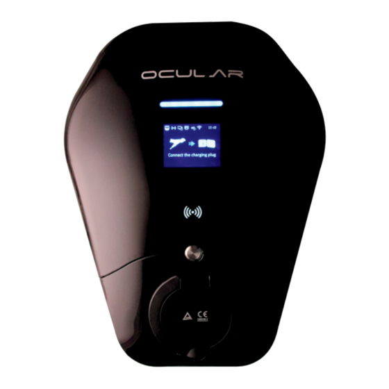
Page 5: Product Overview
SELF-MONITORING AND RECOVERY PRODUCT OVERVIEW The charger will automatically resume charging after a minor fault such as OVP, UVP, OTP or OCP, with no user intervention required. OCPP 1.6J, 2.0 FULL PROFILES & SMART CHARGING SUPPORT The charger supports OCPP 1.6J, 2.0 including the latest smart charging profile to balance the load of charging stations with limited power supply. -
Page 6: Safety Instructions
SAVE THESE IMPORTANT SAFETY INSTRUCTIONS This document contains important instructions and warnings that must be followed when installing and maintaining the workplace pedestal charger WARNINGS: CAUTIONS: Do not install or use the charger near flammable, explosive, harsh, or combustible The charger should be installed only by a qualified approved technician. materials, chemicals, or vapors. -
Page 7: Installation
NOTES BEFORE INSTALLATION STEP ONE - CHECK BOX CONTENTS The charger should be protected by an external Residual Current If any of these components are damaged or missing, contact Ocular Device (RCD) to be installed in the upstream circuit which complies Charging. -
Page 8: Step Two- Wall Mounting & Wiring
STEP TWO– WALL MOUNTING & WIRING 3. Electrical Connection Remove the backplate from the charger and mount the backplate to the wall In Australia only the TN network is used, as shown on the label on the back plate. Connect the cable through the bottom of the junction box ensure conduit is connected to the bottom of the power box conduit Ferrule crimps must be used to ensure warranty is valid... -
Page 9: Step Three - Install The Charger
Please connect the ethernet cable to the WAN port this should connect automatically to the internet if there's no IT restrictions, ( if static IP address is required please refer to the Ocular Configuration manual) (See Ocular or local supplier for manual) - Page 10 This hot spot will have the following SSID: IOC – 2.4GHz - ****** The password for this Hotspot is: IOC12345 Step 2: Navigate to the web-interface of the Ocular Charger After being connected to the Hotspot, open Microsoft Edge or Google Choose the Wi-Fi SSID that you prefer, and then input the Wi-Fi Password Chrome and navigate to: 192.168.10.1:8900...
- Page 11 Please note: Step 5 and onwards is for Ocular IQ Solar Installation only.
-
Page 12: Wiring Diagram
Distribution Board SDaodwaiojdoaiwjd CT Clamp Connection Regarding the installation of the Ocular IQ Solar, each charger will need a power connection and an additional internet connection to allow smart charging with energy tracking , smart control and load management. Power connection... -
Page 13: Step Five- Ct Clamp Installation & Wiring
STEP FIVE– CT CLAMP INSTALLATION & WIRING 1. Please run the CT clamp wires through the grey gland/hole 2. Please connect internally following this diagram: located at the bottom of the charger. BLACK... -
Page 14: Step Six - Ct Clamp Spec Reqirements
Prior to setting up the CT clamps, please ensure that you have the correct CT and CT Ratio setup. Mechanical Specifications Only use CT clamps provided by Ocular – The wrong CT clamps will cause a misreading and void warranty. If you must use your own CT please speak to Ocular and confirm suitability. -
Page 15: Step Seven - Ct Clamp Configuration
STEP SEVEN – CT CLAMP CONFIGURATION Do not change settings other than outlined below as this may affect operations. Step 1: Log in to the configuration page of the web page. Step 2: Go to the 'Advanced' section Step 3: Navigate to the balance page. Step 4: In 'Mode' , select 'Master TCP Server'. -
Page 16: Step Eight (A) - Ct Single Phase Setup
STEP EIGHT (A) – CT SINGLE PHASE SETUP The CT clamp is connected to the P1-N1 terminals using the red and black signal wires. The CT clamp is installed in the main MCB input terminal at the L1 position, with the direction pointing from the grid to the home as below Do not change settings other than outlined below as this may affect operations. - Page 17 SINGLE PHASE CT INSTALL...
-
Page 18: Step Eight (B) - Ct Three Phase Setup
STEP EIGHT (B) – CT THREE PHASE SETUP CT Clamp 1, CT Clamp 2, and CT Clamp 3 are connected to the P1-N1, P2-N2, and P3-N3 terminals respectively using the red and black signal wires. CT Clamp1, CT Clamp2, and CT Clamp3 are installed in the main MCB input terminals at the L1, L2, and L3 positions respectively, with the direction pointing towards the direction of the grid. - Page 19 THREE-PHASE CT INSTALL...
-
Page 20: Step Nine - Ct Clamp Configuration (Continued)
STEP NINE – CT CLAMP CONFIGURATION (Continued) Grid Current (*please note scale is 0.1A so 1 Amp is a value of 10*) Rated Current: This is the maximum current that the main MCB can handle. Safe Current: This is the safe current reserved to prevent the circuit from overloading. - Page 21 STEP NINE – CT CLAMP CONFIGURATION (Continued) Data Reporting Interval Idle I nterval for reporting status when idle (Default is 30 seconds) : Charging I nterval for reporting status when charging (Default is : 30 seconds)
-
Page 22: Step Ten - Verify The Installation
Provide these details to the charger owner to login to the back end of the charger username: useradmin password: 12345678 Server Settings: By default, the offline mode is turned off which means it’s online. You should not need to change these setting unless advised by Ocular Charging... - Page 23 USER LOGIN After being connected to the Hotspot, open Microsoft Edge or Google Chrome and navigate to: 192.168.10.1:8900 The web interface will ask for Username and Password, the information is: username: useradmin password: 12345678 INSTALLER LOGIN After being connected to the Hotspot, open Microsoft Edge or Google Chrome and navigate to: 192.168.10.1:8900 The web interface will ask for Username and Password, the information is: Username : install...
-
Page 24: Lcd Display Details
LCD SCREEN DISPLAY DETAILS Welcome Screen Scan the QR code or swipe the Connect the charging plug RFID card to start charging Suspended by EV Charging in process Suspended by EVSE... - Page 25 Remove the charging plug Automatic upgrade mode Software downloading and activated upgrading automatically Network upgrade mode Software update error Micro SD card upgrade mode...
- Page 26 Factory Reset Invalid Authorisation Service not available RFID Activated Reserved Mode Explanation of ICONS...
-
Page 27: Troubleshooting
If the situation persists, contact your installer for Technical Support. MAINTENANCE AND REPAIR Regularly inspect the Charger components for damage. If damage is found, contact Ocular Charging The Electric Vehicle Charger contains no user-serviceable components. If the unit is not operating correctly, contact your... - Page 28 OCULAR CHARGING AUSTRALIA Email: sales@ocularcharging.com.au Web: www.ocularcharging.com.au...
Need help?
Do you have a question about the IQ WALLBOX and is the answer not in the manual?
Questions and answers