
Related Manuals for ecactus WH-SPHA3.6H-5.12kWh

Summary of Contents for ecactus WH-SPHA3.6H-5.12kWh
- Page 1 WH-SPHA3.6H-5.12kWh WH-SPHA3.6H-10.24kWh WH-SPHA5.0H-5.12kWh WH-SPHA5.0H-10.24kWh WH-SPHA6.0H-5.12kWh WH-SPHA6.0H-10.24kWh USER MANUAL...
-
Page 2: Table Of Contents
CONTENTS 1. GENERAL INTRODUCTION ............ 5 System Introduction ..................5 Safety Introduction ..................5 1.2.1 Protection of Warning Sign ..............5 Packing List ..................... 7 System Appearance ..................9 Liability Limitation ..................12 2.INSTALLATION................ 12 2.1 Installation Site and Environment ......... 12 2.1.1 General ...................... - Page 3 3.3.1 Emergency Procedure ................35 3.3.2 First Aid Measures ..................35 3.3.3 Firefighting Measures ................36 4. ECACTUS CONFIGURATION & WIFI RELOAD ....37 4.1 Preparation ................. 37 4.2 Wi-Fi Reset & Reload ............38 4.3 Install Side Plate ..............39 5.EMS CONFIGURATIONS ............
- Page 4 Copyright Statement This manual is under the copyright of JIANGSU WEIHENG INTELLIGENT TECHNOLOGY CO., LTD.(hereinafter referred to as WIFO PRO), with all rights reserved. Please keep the manual properly and operate in strict accordance with all safety and operating instructions in this manual. Please do not operate the system before reading through the manual.
-
Page 5: General Introduction
BESS can store the DC power generated by the PV array into the battery, or convert it into AC power to loads. This user manual applies to the following products : WH-SPHA3.6H-5.12kWh/WH-SPHA3.6H- 10.24kWh/WH-SPHA5.0H-5.12kWh/WH-SPHA5.0H-10.24kWh/WH-SPHA6.0H- 5.12kWh/WH-SPHA6.0H-10.24kWh. - Page 6 ● SAFETY WARNING(AS4777.2:2020 CL7.3.1, CL 7.3.3, CL7.3.5) Any installation and operation on BESS must be performed by qualified electricians, in compliance with standards, wiring rules or requirements of local grid authorities or companies (like AS 4777 and AS/ NZS 3000 in Australia). Before any wiring connection or electrical operation on BESS, all battery and AC power must be disconnected from BESS for at least 5 minutes to make sure BESS is totally isolated to avoid electric shock.
-
Page 7: Packing List
1.3 Packing List WH-SPHA-3.6H/5.0H/6.0H-5.12kWh 1xWifi Terminal Document upper and lower module accessory accessory connection plate 1x Meter 1xQuick Installation Label accessory 4xM4*10 1xM4*10(PE) Manual Disassemble 1x Back 4xCushions 10xCable ties 2xφ10*60 tool plate 1 x Left side plate 1 x Right side plate Battery box side plate*1 1 x Left side plate 1 x Right side plate... - Page 8 WH-SPHA-3.6H/5.0H/6.0H-10.24kWh 1xWifi 2xcables Terminal Document 4x upper and lower module accessory accessory connection board 1x Meter 1xQuick Installation Label 8xM4*10 1xM4*10(PE) accessory Disassemble 2x Back plate 4xCushions 15xCable 4xφ10*60 tool ties 1 x Left side plate 1 x Right side plate Battery box side plate*2 1x Left side plate 1 x Right side plate...
-
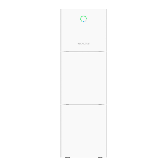
Page 9: System Appearance
1.4 System Appearance LED INDICATORS: STATUS LED INDICATORS Waiting Blue LED blinking, with an interval of 1sec Checking Blue LED blinking, with an interval of 0.5sec Normal Blue LED on DSP fault Red LED on Battery com. fault Red LED blinking, with an interval of 1sec Meter com. - Page 10 Terminals of BESS:...
- Page 11 Object Description Tool requirements and torque Grid output & EPS output Cross screwdriver 2.5 N·m Wifi port Plug and play terminals no tool required VPP communication port Flat head screwdriver USB port for upgrading Plug and play terminals no tool required Meter communication port &...
-
Page 12: Liability Limitation
Battery switch 1.5 Liability Limitation WIFO PRO does not assume any direct or indirect liability for any product damage or property loss caused by the following conditions. ◆ Product modified, design changed or parts replaced without Wifo Pro’s authorization; ◆ Changes, or attempted repairs and erasing of series number or seals by non Wifo Pro technician;... -
Page 13: Restricted Locations
BESS is outdoor version and can be installed in an outdoor or an indoor location. The BESS is naturally ventilated. The location should therefore be clean, dry and adequately ventilated. The mounting location must allow free access to the unit for installation and maintenance purposes, and the system panels must not be blocked. - Page 14 The following distances must remain empty: (1) 500 mm beside the BESS; (2) 800 mm above the BESS; (3) 500 mm before the BESS.
-
Page 15: Select Mounting Location
2.1.4 SELECT MOUNTING LOCATION BESS’s protection and convenient maintenance, mounting location for BESS should be selected carefully based on the following rules: Rule 1. The BESS should be installed on a solid surface, where is suitable for inverter’s dimensions and weight. Rule 2. -
Page 16: Installation Steps
Rule 5. The BESS should be installed at eye level for convenient maintenance. Rule 6. Product label on The BESS should be clearly visible after installation. 2.2 Installation Steps Unpacking the battery box and inverter box. Unpacking the battery box Unpacking the inverter box 2.2.1Battery Box Installation Installation Tools:... - Page 17 For 10kWh BESS: Step 1 : Paste the cushions of the battery box Find four cushions from the inverter packaging accessory and paste them at the four corners of the bottom of the battery box. Step 2 :Back plate pre-tightening Remove the installation back plate from the inverter attachment package and pre-tighten the back plate to the top of the battery box with two M4*10 screws, as shown in the figure below:...
- Page 18 Step 4 : Fix expansion tube Find the expansion screw from the inverter box accessory package and hammer it into the pre-drilled hole so that its surface is flush with the wall. Step 5 : Fix battery box and back plate Rotate the back plate in place and spin the expansion pipe into the locking back plate with self- tapping screws (note that the battery box is fixed with the back plate).
- Page 19 Step 7 :Install the second battery box Put the second battery box smoothly on the top of the first battery box, and be careful not to hit the Back plate. Step 8 : drilling holes Put the pre-installed battery box in a specified position, so that it is close to the fixture, mark it according to the hole position on the back plate, then rotate the back plate at an angle (or take the backboard away), and drill holes at the fixture with Ø10mm.
- Page 20 Step 9 : Fix expansion tube Find the expansion screw from the inverter box accessory package and hammer it into the pre- drilled hole so that its surface is flush with the wall. Step 10 : Fix battery box and back plate Rotate the back plate in place and spin the expansion pipe into the locking back plate with self- tapping screws (note that the battery box is fixed with the back plate).
-
Page 21: Inverter Box Installation
Step 11 :Fix the upper and lower connection plate. (Torque 2.5N.m) 2.2.2 Inverter Box Installation Step 1 :Take the inverter out of the box and place it smoothly on the battery box. Be careful not to damage the cables of the inverter when moving it. Step 2 :Fix the upper and lower connection board to the inverter box... - Page 22 Pre-lock the back plate and inverter with M4*10L stainless steel screws, then lock the battery box and inverter with a upper and lower connection plate, and finally lock the back plate with the screws of the inverter. (Torque 2.5N.m) Step 3 :Install Wifi module Find the Wifi module in the accessory package and insert it into the base, then tighten the Plastic nut.
-
Page 23: Cable Connection
2.3 Cable Connection 2.3.1General Make sure all the switches and breakers on the BESS are turned off. Note: For Australia and New Zealand the PV SWITCH is not integrated. Note: The external isolation devices for PV array ports shall include the requirement of an additional external break switching device that conforms to the requirements AS/NZS 4777.1 2.3.2 Connect the Inverter Box and Battery Box Recommended cables and terminals:... - Page 24 For 10kWh BESS: Make sure all the switches and breakers on the BESS are turned off. Step 1: Untie the cable ties. Step 2: First open the waterproof cover of the corresponding terminal, and insert the corresponding terminal in turn according to the cable label.
- Page 25 Step 3: Connect the cables between two battery boxes Find two wires from the inverter box and insert the corresponding port according to the wire number. Connect the communication cables Step 4: Open the communication cover plate and wiring according to the print instructions on the communication cover board.
- Page 26 Step 5:GRID and EPS cables Open the waterproof cover plate and connect according to the type description on the box. Open the press nut of the waterproof joint and pull out the seal race. Then penetrate the wire into the hole. Note: The length of the cable shall be less than 30 meters.
- Page 27 3. Insert the terminal into the wiring seat, use a cross screwdriver to lock the screws (2.5N.m), and tighten the nut. 4. Fix the waterproof cover and lock it.
- Page 28 Step 6 : Connect PE cable. Grade Description Value Outside Diameter 5.5-8.0mm Step 7:Connect PV cables Conduct Wire Length Conduct Core Section 4-6mm 1. Press the terminal;...
- Page 29 2. Plug through the terminal and lock the nut; 3. Finish the interpolation.
-
Page 30: System Wiring
2.3.3 System Wiring Please select breaker accor the specification below: ding to Choose the proper breaker: Model ① ② ③④ WH-SPHA3.68H- 50A/230V AC 32A/230V AC 5.12kWh/10.24kWh breaker breaker Depends on household loads (usually already WH-SPHA5.0H- 63A/230V AC 32A/230V AC placed in the grid 5.12kWh/10.24kWh breaker breaker... - Page 31 ●System Connection Diagrams Note: For Australia safety country, the neutral cable of On-Grid side and Back-Up side must be connected together, otherwise Back-Up function will not work. Note: The back-up PE line and rack earth must be grounded properly and effectively. Otherwise the back-up function may be abnormal when the grid fail.
-
Page 32: Power Meter(As4777.2:2020 Cl7.3.4
2.3.4 Power Meter (AS4777.2:2020 CL7.3.4) The electricity meter should be mounted and connected at the grid transition point so that it can measure the grid reference and feed-in power. CT meter ratio and accuracy table Manufacturer Model CT ratio Accuracy Acrel Co., Ltd ACR10R-D16TE 3000... -
Page 33: System Operation
3.SYSTEM OPERATION 3.1 Switch On Warning: Please check the installation again before turning on the system. Step 1: Turn on the battery switch on every battery module Step 2 : Open the battery breaker cover and turn on the battery breaker. - Page 34 Step 3: Turn on the PV switch. Note: For Australia and New Zealand the PV SWITCH is not integrated. Note: The external isolation devices for PV array ports shall include the requirement of an additional external break switching device that conforms to the requirements AS/NZS 4777.1 Step 4: Turn on the grid breaker.
-
Page 35: Switch Off
3.2 Switch Off Step 1: If backup load is applied, turn off the backup load first, and then turn off the backup breaker. Step 2: Turn off the grid breaker. Step 3: Turn off the PV switch. Step 4: Open the battery breaker cover and turn off the battery breaker. Step 5: Turn off the battery switch on every battery module. -
Page 36: Firefighting Measures
unconscious. Take a medical treatment immediately. 3.3.3 Firefighting Measures Extinguishing media: Dry power, sand, carbon dioxide (CO2), water spray Fire precautions and protective measures: Flammable properties: Lithium ion batteries contain flammable liquid electrolyte that may vent, ignite and produce sparks When subjected to high temperature(> 150℃), When damaged or abused (e.g., mechanical damage or electrical overcharge). -
Page 37: Ecactus Configuration & Wifi Reload
• This part shows eCactus configuration step by step. 4.1 Preparation 1. Inverter must be powered up with only PV power. 2. Need a router with available internet access to eCactus application center. 3. A smart phone managed by Android or iOS operating system. STEP1 1. -
Page 38: Wi-Fi Reset & Reload
Please make sure the password is right the same with the router’s. If everything is right well, the Wi-Fi LED on inverter will change from double blink to quartic blink then to solid status, Which means Wi-Fi is connected to eCactus successfully. -
Page 39: Install Side Plate
4.3 Install Side Plate Confirm that the left and right side plates are installed respectively after the BESS is working properly.:... -
Page 40: Ems Configurations
2.Load Shifting Power from battery will be charge and discharged as you configured. 3.Backup: eCactus will not discharge battery unless power grid is off. At that time, eCactus can support your family power usage by discharging battery. Working Modes: Navigate to Customize tab and you can one of three operation modes from eCactus App. -
Page 41: Wifo Monitor Configuration
6. Wifo Monitor CONFIGURATION You can change and check the country code and power quality response modes via our configuration software “Wifo Monitor”. Please contact our technical support for more information. For AS/NZS 4777.2:2020, you can change the Region requirements: Australia A, Australia B, Australia C, New Zealand. - Page 42 (2) Volt-Watt mode click the “Ov” button and open the setting page. The default protection settings points are loaded according to AS/NZS 4777.2:2020 Table 3.6.
- Page 43 U2=110% means Vw1= 110%*230=253V U3=113.04% means Vw2=113.04%*230=260V (3) Volt-Var mode click the “Reac” button and open the setting page. The default protection settings points are loaded according to AS/NZS 4777.2:2020 Table 3.7.
- Page 44 U1 means Vv1 U2 means Vv2 U3 means Vv3 U4 means Vv4 (4) Volt-watt set-point when charging(Under Voltage) click the “UV” button and open the setting page. The default protection settings points are loaded according to AS/NZS 4777.2:2020 Table 3.8.
-
Page 45: Cleaning And Maintenance
U2 means Vw1-ch U3 means Vw2-ch (5)View the inverter firmware version(in read-only mode) Inverter firmware version includes DSP1 Version, DSP2 Version, BMS Version and BMS Version. 7. Cleaning and Maintenance Power off the system first. ● Shut down procedure : Step 1: If backup load is applied, turn off the backup load first, and then turn off the backup breaker. -
Page 46: Cleaning
Step 3: Turn off the PV switch. Step 4: Open the battery breaker cover and turn off the battery breaker. Step 5: Turn off the battery switch on every battery module. Step 6: Close the battery breaker cover. 7.1 Cleaning When the BESS needs to be cleaned, please power off the system first. -
Page 47: Annex
8.ANNEX 8.1 Datasheet(AS4777.2: CL 7.3.1,CL 7.3.2, CL7.3.3, CL,7.3.6) All-In-One Spec. WH-SPHA3.6H- WH-SPHA5.0H- WH-SPHA6.0H- 5.12kWh 5.12kWh 5.12kWh WH-SPHA3.6H- WH-SPHA5.0H- WH-SPHA6.0H- Model 10.24kWh 10.24kWh 10.24kWh PV Input Absolute max Voltage [d.c.V] MPPT Voltage Range [d.c.V] 100...550 Max. DC Input Power [W] 4800 6650 8000 Start-up Voltage [d.c.V]... - Page 48 EPS Output (With Battery) Max. Output Power [W] 3600 5000 6000 Rated Apparent Power [VA] 4320 6000 7200 Max. Apparent Power [VA] 4320 6000 7200 230 (±2%) Rated Voltage [a.c.V] 50/60 (±0.2%) Norminal Frequency [Hz] Rated Output Current [a.c.A] 18.8 26.1 31.3 Inrush current[a.c.A]...
- Page 49 Protective class Class Ⅰ Active anti-islanding method frequency shift Human Interface LED/APP BMS Communication Interface RS485/CAN RS485 Meter Communication Interface Noise Emission [dB] < 25 < 5 Standby Power Consumption [W] Safety and Approvals IEC62040.1:2019 AS/NZS 4777.2:2020 IEC 62109-1&-2 Safety IEC62619 UN38.3 IEC60730-1 EN IEC 61000-6-2:2019 EN IEC 61000-6-3:2021...
-
Page 50: Labels
9.LABELS 9.1 Inverter label... -
Page 51: Battery Label
9.2 Battery label...
Need help?
Do you have a question about the WH-SPHA3.6H-5.12kWh and is the answer not in the manual?
Questions and answers