
Related Manuals for ecactus WH-SPHA3.6H-5.12kWh


Summary of Contents for ecactus WH-SPHA3.6H-5.12kWh
- Page 1 WH-SPHA3.6H-5.12kWh WH-SPHA3.6H-10.24kWh WH-SPHA4.6H-5.12kWh WH-SPHA4.6H-10.24kWh WH-SPHA5.0H-5.12kWh WH-SPHA5.0H-10.24kWh WH-SPHA6.0H-5.12kWh WH-SPHA6.0H-10.24kWh USER MANUAL...
-
Page 2: Table Of Contents
CONTENTS 1. GENERAL INTRODUCTION ......................5 1.1 System Introduction ....................... 5 1.2 Safety Introduction ......................... 5 1.2.1 Protection of Warning Sign ....................5 1.3 Packing List ..........................7 1.4 System Appearance ........................ 9 1.5 Liability Limitation ......................... 12 2.INSTALLATION ..........................12 2.1 Installation Site and Environment .................. - Page 3 3.3.1 Emergency Procedure ....................... 39 3.3.2 First Aid Measures ......................39 3.3.3 Firefighting Measures ....................... 40 4. ECACTUS CONFIGURATION & WIFI RELOAD............... 41 4.1 Preparation ..........................41 4.2 Wi-Fi Reset & Reload ......................42 4.3 Install Side Plate ........................43 5.EMS CONFIGURATIONS ......................
- Page 4 Copyright Statement This manual is under the copyright of JIANGSU WEIHENG INTELLIGENT TECHNOLOGY CO., LTD.(hereinafter referred to as WIFO PRO), with all rights reserved. Please keep the manual properly and operate in strict accordance with all safety and operating instructions in this manual. Please do not operate the system before reading through the manual.
-
Page 5: General Introduction
WH-SPHA series hybrid all-in-one battery energy storage system (BESS) is designed for both indoor and outdoor use. BESS can store the DC power generated by the PV array into the battery, or convert it into AC power to loads. This user manual applies to the following products: WH-SPHA3.6H-5.12kWh/WH-SPHA3.6H-10.24kWh/WH- SPHA4.6H-5.12kWh/WH-SPHA4.6H-10.24kWh/WH-SPHA5.0H-5.12kWh/WH- SPHA5.0H-10.24kWh/WH-SPHA6.0H-5.12kWh/WH-SPHA6.0H-10.24kWh. - Page 6 The maximum operating ambient temperature is 55 ℃. Product should not be used in multiple phase combinations. In the event of an earth fault, an error message will be sent to eCactus App and the status lamp on our product will turn into red.
-
Page 7: Packing List
1.3 Packing List WH-SPHA-3.6H/4.6H/5.0H/6.0H-5.12kWh 1xWifi module Terminal Document upper and lower accessory accessory connection plate 1x Meter ( Three 1xQuick Phase Meter/ Installation Label accessory 8xM4*10 1xM4*10(PE) Single Phase Manual Meter) Disassemble 1x Back plate 4xCushions 10xCable ties 2xφ10*60 tool 1 x Left side plate 1 x Right side plate Battery box side plate*1... - Page 8 WH-SPHA-3.6H/4.6H/5.0H/6.0H-10.24kWh Terminal Document 4x upper and lower 1xWifi module 2xcables accessory accessory connection board 1x Meter ( Three Label Phase Meter/ 1xQuick Installation 16xM4*10 1xM4*10(PE) accessory Single Phase Meter) 15xCable Disassemble 2x Back plate 4xCushions 4xφ10*60 tool ties 1 x Right side plate 1 x Left side plate Battery box side plate*2 1x Left side plate...
-
Page 9: System Appearance
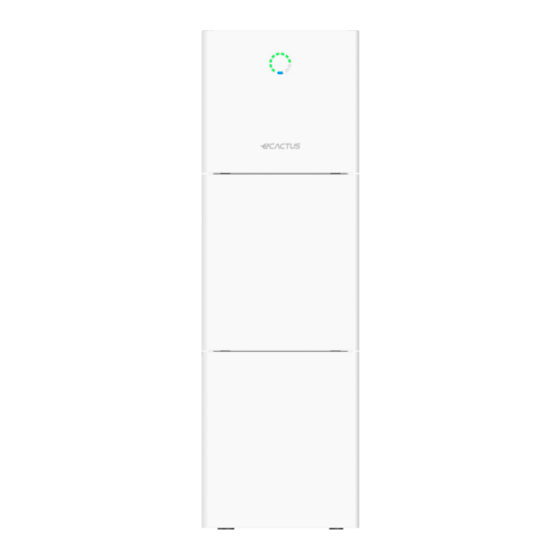
1.4 System Appearance LED INDICATORS: STATUS LED INDICATORS Waiting Blue LED blinking, with an interval of 1sec Checking Blue LED blinking, with an interval of 0.5sec Normal Blue LED on DSP fault Red LED on Battery com. fault Red LED blinking, with an interval of 1sec Meter com. - Page 10 Terminals of BESS:...
- Page 11 Object Description Tool requirements and torque Grid output & EPS output Cross screwdriver 2.5 N·m Wifi port Plug and play terminals no tool required VPP communication port Flat head screwdriver USB port for upgrading Plug and play terminals no tool required Meter communication port &...
-
Page 12: Liability Limitation
Battery switch The battery switch isolates the internal battery modules which are connected in series, the battery switch should not be used to disconnect the batteries under load. Isolation of battery under load is achieved via battery breaker. 1.5 Liability Limitation WIFO PRO does not assume any direct or indirect liability for any product damage or property loss caused by the following conditions. -
Page 13: Restricted Locations
installation and maintenance purposes, and the system panels must not be blocked. The following locations are not allowed for installation: ◆ habitable rooms; ◆ ceiling cavities or wall cavities; ◆ on roofs that are not specifically considered suitable; ◆ access / exit areas or under stairs / access walkways; ◆... - Page 14 (1) 500 mm beside the BESS; (2) 800 mm above the BESS; (3) 500 mm before the BESS.
-
Page 15: Select Mounting Location
2.1.4 SELECT MOUNTING LOCATION BESS’s protection and convenient maintenance, mounting location for BESS should be selected carefully based on the following rules: Rule 1. The BESS should be installed on a solid surface, where is suitable for inverter’s dimensions and weight. Rule 2. -
Page 16: Installation Steps
Rule 5. The BESS should be installed at eye level for convenient maintenance. Rule 6. Product label on The BESS should be clearly visible after installation. 2.2 Installation Steps Unpacking the battery box and inverter box. Unpacking the battery box Unpacking the inverter box 2.2.1Battery Box Installation... - Page 17 For 10kWh BESS: Step 1 : Paste the cushions of the battery box Find four cushions from the inverter packaging accessory and paste them at the four corners of the bottom of the battery box. Step 2 :Back plate pre-tightening Remove the installation back plate from the inverter attachment package and pre-tighten the back plate to the top of the battery box with two M4*10 screws, as shown in the figure below:...
- Page 18 Step 4 : Fix expansion tube Find the expansion screw from the inverter box accessory package and hammer it into the pre-drilled hole so that its surface is flush with the wall. Step 5 : Fix battery box and back plate Rotate the back plate in place and spin the expansion pipe into the locking back plate with self- tapping screws (note that the battery box is fixed with the back plate).
- Page 19 Step 7 :Install the second battery box Put the second battery box smoothly on the top of the first battery box, and be careful not to hit the Back plate. Step 8 : drilling holes Put the pre-installed battery box in a specified position, so that it is close to the fixture, mark it according to the hole position on the back plate, then rotate the back plate at an angle (or take the backboard away), and drill holes at the fixture with Ø10mm.
- Page 20 Step 9 : Fix expansion tube Find the expansion screw from the inverter box accessory package and hammer it into the pre- drilled hole so that its surface is flush with the wall. Step 10 : Fix battery box and back plate Rotate the back plate in place and spin the expansion pipe into the locking back plate with self- tapping screws (note that the battery box is fixed with the back plate).
-
Page 21: Inverter Box Installation
Step 1 1 :Fix the upper and lower connection plate. (Torque 2.5N.m) 2.2.2 Inverter Box Installation Step 1 :Take the inverter out of the box and place it smoothly on the battery box. Be careful not to damage the cables of the inverter when moving it. - Page 22 Step 2 :Fix the upper and lower connection board to the inverter box Pre-lock the back plate and inverter with M4*10L stainless steel screws, then lock the battery box and inverter with a upper and lower connection plate, and finally lock the back plate with the screws of the inverter. (Torque 2.5N.m)...
-
Page 23: Cable Connection
2.3 Cable Connection 2.3.1General Make sure all the switches and breakers on the BESS are turned off. Note: For Australia and New Zealand the PV SWITCH is not integrated. Note: The external isolation devices for PV array ports shall include the requirement of an additional external break switching device that conforms to the requirements AS/NZS 4777.1 2.3.2 Connect the Inverter Box and Battery Box Recommended cables and terminals:... - Page 24 For 10kWh BESS: Make sure all the switches and breakers on the BESS are turned off. Step 1: Untie the cable ties. Step 2: First open the waterproof cover of the corresponding terminal, and insert the corresponding terminal in turn according to the cable label.
- Page 25 Step 3: Connect the cables between two battery boxes Find two wires from the inverter box and insert the corresponding port according to the wire number. Connect the communication cables Step 4: Open the communication cover plate and wiring according to the print instructions on the communication cover board.
- Page 26 Step 5:GRID and EPS cables Open the waterproof cover plate and connect according to the type description on the box. Open the press nut of the waterproof joint and pull out the seal race. Then penetrate the wire into the hole. Note: The length of the cable shall be less than 30 meters.
- Page 27 2. Put the "I" terminal into the cable and press it tightly with pressure line clamps. 3. Insert the terminal into the wiring seat, use a cross screwdriver to lock the screws (2.5N.m), and tighten the nut.
- Page 28 4. Fix the waterproof cover and lock it. Note: Declaration for back-up function: Some external factors may cause the back-up switching time more than 10 ms, so do not connect loads that depend on a stable energy supply for a reliable operation. ...
- Page 29 2. Plug through the terminal and lock the nut; Grade Description Value Outside Diameter 5.5-8.0mm Conduct Wire Length Conduct Core Section 4-6mm 3. Finish the interpolation.
-
Page 30: System Wiring
2.3.3 System Wiring Please select breaker accor the specification below: ding to Three Phase Meter Single Phase Meter... - Page 31 Choose the proper breaker: Model ① ② ③④ WH-SPHA3.6H- 50A/230V AC 32A/230V AC 5.12kWh/10.24kWh breaker breaker WH-SPHA4.6H- 63A/230V AC 32A/230V AC Depends on household loads (usually already 5.12kWh/10.24kWh breaker breaker placed in the grid WH-SPHA5.0H- 63A/230V AC 32A/230V AC distribution box) 5.12kWh/10.24kWh breaker breaker...
-
Page 32: Power Meter
Note: The back-up PE line and rack earth must be grounded properly and effectively. Otherwise the back-up function may be abnormal when the grid fail. 2.3.4 Power Meter The electricity meter should be mounted and connected at the grid transition point so that it can measure the grid reference and feed-in power. -
Page 33: Derd Connection
2.4 DERD Connection DRED is used for Australia and New Zealand installation to support several demand response modes. Demond response Requirement mode DRM0 Disconnected Import power = 0 & Generate power = 0 DRM1 Import power = 0 DRM2 Import power < 50% DRM3 Import power <... - Page 34 DRED terminal ●DRED Wire connection Open the communication cover plate and wiring according to the print instructions on the communication cover board. Open the press nut of the waterproof connector, pull out the seal race, then penetrate the conductor into the hole, connect the corresponding label in turn, then tighten the forced nut, and finally lock the waterproof cover plate.
-
Page 36: System Operation
3.SYSTEM OPERATION 3.1 Switch On Warning: Please check the installation again before turning on the system. Step 1: Turn on the battery switch on every battery module Note: The battery switch isolates the internal battery modules which are connected in series, the battery switch should not be used to disconnect the batteries under load. - Page 37 Step 3: Turn on the PV switch. Note: For Australia and New Zealand the PV SWITCH is not integrated. Note: The external isolation devices for PV array ports shall include the requirement of an additional external break switching device that conforms to the requirements AS/NZS 4777.1...
- Page 38 Step 4: Turn on the grid breaker. Step 5: If backup load is applied, switch on the backup breaker. Step 6: Close the battery breaker cover. Step 7: Configure the WIFI stick (Only if this is the first time turning on the system). Please follow the instructions in section 4 to section 5.
-
Page 39: Switch Off
3.2 Switch Off Step 1: If backup load is applied, turn off the backup load first, and then turn off the backup breaker. Step 2: Turn off the grid breaker. Step 3: Turn off the PV switch. Step 4: Open the battery breaker cover and turn off the battery breaker. Step 5: Turn off the battery switch on every battery module. -
Page 40: Firefighting Measures
unconscious. Take a medical treatment immediately. 3.3.3 Firefighting Measures Extinguishing media: Dry power, sand, carbon dioxide (CO2), water spray Fire precautions and protective measures: Flammable properties: Lithium ion batteries contain flammable liquid electrolyte that may vent, ignite and produce sparks When subjected to high temperature(> 150℃), When damaged or abused (e.g., mechanical damage or electrical overcharge). -
Page 41: Ecactus Configuration & Wifi Reload
• This part shows eCactus configuration step by step. 4.1 Preparation 1. Inverter must be powered up with only PV power. 2. Need a router with available Internet access to the eCactus application center. 3. An Android or iOS smart phone STEP1... -
Page 42: Wi-Fi Reset & Reload
2. Ensure that the signal strength between the Wifi module and the wireless network is stable. If everything is right well, the Wi-Fi LED on inverter will change from double blink quartic blink then to solid status, Which means Wi-Fi is connected to eCactus successfully. 4.2 Wi-Fi Reset & Reload Wi-Fi Reset means restarting Wi-Fi module, Wi-Fi settings will be reprocessed and saved. -
Page 43: Install Side Plate
4.3 Install Side Plate Confirm that the left and right side plates are installed respectively after the BESS is working properly.:... -
Page 44: Ems Configurations
2.Load Shifting Power from battery will be charge and discharged as you configured. 3.Backup: eCactus will not discharge battery unless power grid is off. At that time, eCactus can support your family power usage by discharging battery. Working Modes: Navigate to Customize tab and you can one of three operation modes from eCactus App. -
Page 45: Ecos Hub (Pc) User Manual (For Agent)
6. ECOS Hub (PC) User Manual (For Agent) Device list: 1. Device list shows the devices belongs to the current agent account. 2. Clicking the tab to see more information about the device 3. Under operation, the left bottom contains 4 commands to control the device, which are “Start”,” Shutdown”,”... - Page 46 Device info: The device info module shows the device information, inverter information, meter information, eps parameter and battery data. Device information: Inverter information: Meter information:...
- Page 47 EPS parameter: Battery data: Curves This module shows the data curves of the device and supports query by date and export functions. Single curve: You can select no more than 6 data types to form into a single curve.
- Page 48 Group curves: This page shows the 28 different data curves of the device.
- Page 49 Configuration: Battery setting:...
- Page 50 We support 3 different battery charge mode at the moment. Under “Self-Powered” mode, the system uses solar power and battery first rather than grid power. The battery capacity will not lower than setting percentage. Under “Loading shifting” mode, user can customize the charging and discharging based on time. Under “backup”...
- Page 51 Safety Parameters: The user can change device safety parameters on this page. Active limit & Reactive limit: The user can change active and reactive limit settings on these pages.
- Page 52 Setting: The user can change some settings on this page. Energy setting: The agent only can check the energy settings of the device on this page. Firmware Upgrade: Agent can help user upgrade their device firmware on this page.
- Page 53 Event: This page shows the events, warnings and faults for all devices under the account. It also supports querying events on any date and exporting the queried data.
-
Page 54: Cleaning And Maintenance
7. Cleaning and Maintenance Power off the system first. ● Shut down procedure : Step 1: If backup load is applied, turn off the backup load first, and then turn off the backup breaker. Step 2: Turn off the grid breaker. Step 3: Turn off the PV switch. -
Page 55: Annex
ground. Contact with any part of a grounded battery can result in electrical shock. The likelihood of such shock can be reduced if such grounds are removed during installation and maintenance (applicable to equipment and remote battery supplies not having a grounded supply circuit). 8.ANNEX 8.1 Datasheet All-In-One Spec. - Page 56 Max. inverter backfeed current to array[d.c.A] Isc PV[d.c.A] 18/18 NO. of MPP Trackers NO. of Strings per MPP Tracker WH-BXB5.12 WH-BXB10.24 (For models: (For models: WH-SPHA3.6H-5.12kWh WH-SPHA3.6H-10.24kWh WH-SPHA4.6H-5.12kWh WH-SPHA4.6H-10.24kWh WH-SPHA5.0H-5.12kWh WH-SPHA5.0H-10.24kWh Battery Model WH-SPHA6.0H-5.12kWh) WH-SPHA6.0H-10.24kWh) Battery Capacity LiFePO 5.12kWh LiFePO4 10.24kWh Nominal Battery Voltage 204.8...
- Page 57 Rated Voltage [a.c.V] 230 (±2%) Norminal Frequency [Hz] 50/60 (±0.2%) Rated Output Current [a.c.A] 18.8 26.1 31.3 Inrush current[a.c.A] 16 a.c.A (peak), 11.3 us (duration) Max. output fault current[a.c.A] 57 (peak), 40 (rms) EPS output Maximum output overcurrent protection[a.c.A] < 10 Switch time [ms] THDv @ Linear Load [%] <...
-
Page 58: Labels
BMS Communication Interface RS485/CAN Meter Communication RS485 Interface Noise Emission [dB] < 25 Standby Power Consumption < 5 Safety and Approvals IEC62040.1:2019 AS/NZS 4777.2:2020 IEC 62109-1&-2 Safety IEC62619 UN38.3 IEC60730-1 EN IEC 61000-6-2:2019 EN IEC 61000-6-3:2021 Smax=Srated for AS/NZS 4777.2 Made in China 9.LABELS 9.1 Inverter label... -
Page 59: Battery Label
9.2 Battery label...
Need help?
Do you have a question about the WH-SPHA3.6H-5.12kWh and is the answer not in the manual?
Questions and answers