Optika Italy B-510 Series Instruction Manual
Hide thumbs
Also See for B-510 Series:
- Instruction manual (210 pages) ,
- Instruction manual (156 pages) ,
- Instruction manual (52 pages)
Table of Contents
Advertisement
Available languages
Available languages
Quick Links
Advertisement
Table of Contents

Subscribe to Our Youtube Channel
Related Manuals for Optika Italy B-510 Series


Summary of Contents for Optika Italy B-510 Series
- Page 1 Serie B-510 MANUALE D’ISTRUZIONI Modello B-510MET B-510METR v 1.0 2018...
- Page 2 Indice 1. Avvertenza 2. Simboli 3. Informazioni sulla sicurezza 4. Utilizzo previsto 5. Descrizione dello strumento 6. Disimballaggio 7. Assemblaggio 8. Sommario delle procedure di osservazione in luce riflessa (B-510MET / METR) 9. Uso del microscopio 10. Microfotografia 11. Manutenzione 12.
-
Page 3: Informazioni Sulla Sicurezza
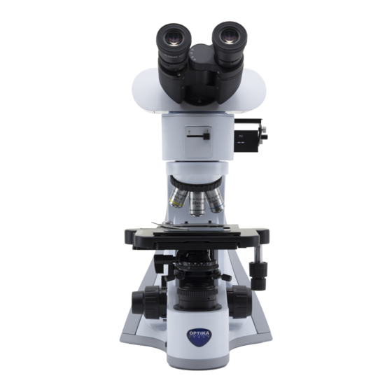
1. Avvertenza Questo microscopio è uno strumento scientifico di alta precisione, progettato per durare a lungo con una minima manutenzione; la realizzazione è secondo i migliori standard ottici e meccanici, per poter essere utilizzato quotidianamente. Vi ricordiamo che questo manuale contiene informazioni importanti per la sicurezza e per la manutenzione dello strumento, e deve quindi essere messo a disposizione di coloro che lo utilizzeranno. - Page 4 5. Descrizione dello strumento (B-510MET) USCITA FOTO/TV TESTA DI OSSERVAZIONE GHIERA DI REGOLAZIONE DIOTTRICA ALLOGGIAMENTO FILTRI ILLUMINATORE LUCE RIFLESSA SLITTA PER ILLUMINAZIONE OBLIQUA REVOLVER OBIETTIVI LEVA DI BLOCCO DI MESSA A FUOCO INTERRUTTORE GENERALE / SELETTORE REGOLAZIONE LUMINOSITÀ Pagina 4...
- Page 5 5. Descrizione dello strumento (B-510MET) (lato opposto) OCULARI TUBO BINOCULARE DIAFRAMMA DI CAMPO (FS) DIAFRAMMA DI APERTURA (AS) ANALIZZATORE POLARIZZATORE FERMAVETRINI TAVOLINO MANOPOLE MANOPOLA MICROMETRICA MANOPOLA MACROMETRICA GHIERA DI REGOLAZIONE DELLA TENSIONE Pagina 5...
- Page 6 5. Descrizione dello strumento (B-510METR) USCITA FOTO/TV TESTA DI OSSERVAZIONE GHIERA DI REGOLAZIONE DIOTTRICA ALLOGGIAMENTO FILTRI SELETTORE LUCE RIFLESSA / LUCE TRASMESSA ILLUMINATORE LUCE RIFLESSA SLITTA PER ILLUMINAZIONE OBLIQUA REVOLVER OBIETTIVI MANOPOLA DI REGOLAZIONE ALTEZZA DIAFRAMMA DI CONDENSATORE APERTURA (LUCE TRASMESSA) LEVA DI DIAFRAMMA DI...
- Page 7 5. Descrizione dello strumento (B-510METR) (lato opposto) OCULARI DIAFRAMMA DI CAMPO (FS) (LUCE RIFLESSA DIAFRAMMA DI APERTURA (AS) (LUCE RIFLESSA) TUBO BINOCULARE ANALIZZATORE POLARIZZATORE FERMAVETRINI TAVOLINO SELETTORE ACCENSIONE LUCE RIFLESSA / LUCE TRASMESSA CONDENSATORE MANOPOLE X/Y MANOPOLA MANOPOLA MICROMETRICA MACROMETRICA GHIERA DI REGOLAZIONE DELLA TENSIONE Pagina 7...
- Page 8 6. Disimballaggio (B-510MET) Il microscopio è riposto in un imballo di polistirolo espanso. Rimuovere il nastro adesivo dal collo ed aprire la parte superiore dell’imballo. Fare attenzione a non far cadere le parti ottiche (obiettivi e oculari) nell’estrarre il microscopio dalla scatola per evitare che vengano danneggiati. Utilizzare entrambe le mani (una intorno allo stativo e una alla base), sfilare il microscopio dal contenitore e appoggiarlo su un piano stabile.
- Page 9 6. Disimballaggio (B-510METR) Il microscopio è riposto in un imballo di polistirolo espanso. Rimuovere il nastro adesivo dal collo ed aprire la parte superiore dell’imballo. Fare attenzione a non far cadere le parti ottiche (obiettivi e oculari) nell’estrarre il microscopio dalla scatola per evitare che vengano danneggiati. Utilizzare entrambe le mani (una intorno allo stativo e una alla base), sfilare il microscopio dal contenitore e appoggiarlo su un piano stabile.
-
Page 10: Procedura Di Montaggio
① Procedura di montaggio 1. Inserire l’illuminatore per luce riflessa ① sullo stativo e serrare la vite di bloccaggio ② con la brugola in dotazione. (Fig.1) ② Fig.1 2. Rimuovere il tappo ③ nella parte posteriore dell’illuminatore. (Fig.2) ③ Fig.2 3. - Page 11 4. Collegare lo spinotto dell’illuminatore ⑥ al connettore ⑦ posto nella parte posteriore in alto dello stativo. (Fig.5) ⑦ ⑥ Fig.5 5. Inserire la testata ottica al di sopra dell’illuminatore e stringere la vite di bloccaggio con la brugola in dotazione. (Fig.6) ►...
- Page 12 9. Inserire il polarizzatore “PO” con la scritta rivolta verso l’operatore (rimuovendo prima la slitta vuota). (Fig.9) Fig.9 10. Inserire l’analizzatore “AN” scritta rivolta verso l’alto (rimuovendo prima le piastrine bianche di copertura sull’illuminatore). (Fig.10-11) Fig.10 Fig.11 11. E’ possibile unire insieme analizzatore e polarizzatore (usando la piastrina di interconnessione) in modo che l’inserimento dei due filtri sia simultaneo.
- Page 13 8. Sommario delle procedure di osservazione in luce riflessa (B-510MET/METR) (Comandi usati ) (Capitolo) Portare su “ON” l’interruttore generale e regolare l’intensità Interruttore generale / selettore (5/9) luminosa. regolazione intensità Spostare sulla posizione “R” il selettore Selettore luce Riflessa/trasmessa del percorso ottico (B-510METR) Rimuovere polarizzatore, analizzatore e filtri dal percorso ottico Fermavetrini...
- Page 14 9. Uso del microscopio ① 1. Regolazione dell’intensità luminosa Agire sulla rotellina di regolazione dell’intensità luminosa per accendere e spegnere lo strumento (B-510MET) e per aumentare o diminuire il voltaggio dell’illuminazione ①. (Fig.14) 2. Regolazione della frizione della manopola macrometrica (Fig. 15) ►...
- Page 15 B-510METR (Fig.18) Il tavolino accetta campioni metallografici con spessore max 35 mm, alloggiati su supporto standard 26 x 76 mm, oppure vetrini standard 26x76 mm. • Allargare il braccio movibile del fermapreparati ④ e posizionare frontalmente i vetrini sul tavolino. •...
-
Page 16: Campo Visivo
8. Centraggio dei diaframmi luce riflessa Diaframma di campo (FS) Spostare il selettore ① sull’illuminatore per luce riflessa nella posizione corrispondente alla lettera “R” (solo B-510METR). (Fig.23) Posizionare il campione sul tavolino, inserire l’obiettivo 10x nel percorso ottico e mettere a fuoco. ①... - Page 17 Solo B-510METR 9. Centraggio del condensatore (Fig.27) Posizionare il campione sul tavolino, inserire l’obiettivo 10x nel percorso ottico e mettere a fuoco. ④ Inserire nel percorso ottico la lente ① frontale del condensatore swing-out ①. Ruotare la ghiera del diaframma di ②...
- Page 18 10. Uso dei filtri (Fig.29) Inserire il filtro ottimale all’osservazione nella fessura posta sulla parte sinistra dell’illuminatore. La prima posizione di clic stop lascia il filtro disinserito, mentre la seconda inserisce il filtro nel percorso ottico. Fig.29 Filtro Applicazione Converte la temperatura colore della sorgente in quella della luce diurna Verde...
- Page 19 10. Microfotografia Installazione dell’adattatore passo “C” 1. Allentare la vite di bloccaggio ① sul tubo trinoculare e rimuovere il tappo antipolvere ② ② ②. (Fig.31) 2. Avvitare l’adattatore passo C ③ alla telecamera installare l’attacco ④ ① ① rotondo del passo C nel foro vuoto del tubo trinoculare, quindi riavvitare la vite di serraggio ①.
-
Page 20: Manutenzione
11. Manutenzione Ambiente di lavoro Si consiglia di utilizzare il microscopio in un ambiente pulito e secco, privo di urti, ad una temperatura fra 0°C e 40°C e con una umidità relativa massima dell’85% (in assenza di condensazione). Si consiglia l’uso di un deumidificatore se necessario. -
Page 21: Guida Alla Risoluzione Dei Problemi
12. Guida alla risoluzione dei problemi Consultare le informazioni riportate nella tabella seguente per risolvere eventuali problemi operativi. PROBLEMA CAUSA SOLUZIONE I. Sezione Ottica: L’illuminazione è accesa ma il I connettori dell’alimentatore non sono Collegarli campo visivo è scuro. ben collegati La luminosità... - Page 22 II. Sezione Meccanica: La manopola macrometrica è difficile L’anello di regolazione della Allentare l’anello di regolazione della ten- da ruotare tensione è troppo stretto sione La messa a fuoco è instabile L’anello di regolazione della Stringere l’anello di regolazione della ten- tensione è...
- Page 23 Smaltimento Ai sensi dell’articolo 13 del decreto legislativo 25 luglio 2005 n°151. “Attuazione delle direttive 2002/95/CE, 2002/96/CE e 2003/108/CE, relative alla riduzione dell’uso di sostanze pericolose nelle apparecchiature elettriche ed elettroniche, nonché allo smaltimento dei rifiuti”. Il simbolo del cassonetto riportato sulla apparecchiatura o sulla sua confezione indica che il prodotto alla fine della propria vita utile deve essere raccolto separatamente degli altri rifiuti.
- Page 25 B-510 Series INSTRUCTION MANUAL Model B-510MET B-510METR v 1.0 2018...
- Page 26 Indice 1. Warning 2. Symbols and conventions 3. Safety Information 4. Intended Use 5. Overview 6. Disassembling 7. Assembling 8. Summary of reflected light observation procedures (B-510MET / METR) 9. Use of the microscope 10. Microphotography 11. Maintenance 12. Troubleshooting guide Equipment disposal Page 26...
-
Page 27: Symbols And Conventions
1. Warning This microscope is a scientific precision instrument designed to last for many years with a minimum of maintenance. It is built to high optical and mechanical standards and to withstand daily use. We remind you that this manual contains important information on safety and maintenance, and that it must therefore be made accessible to the instrument users. - Page 28 5. Overview (B-510MET) PHOTO/TV PORT OBSERVATION HEAD DIOPTER ADJUSTMENT RING FILTER SLIDER REFLECTED LIGHT ILLUMINATOR OBLIQUE ILLUMINATION SLIDER NOSEPIECE OBJECTIVES COARSE UPPER LIMIT KNOB MAIN SWITCH / BRIGHTNESS ADJUSTMENT KNOB Page 28...
- Page 29 5. Overview (B-510MET) (opposite side) EYEPIECES BINOCULAR TUBE FIELD DIAPHRAGM (FS) APERTURE DIAPHRAGM (AS) ANALYZER POLARIZER SLIDE HOLDER STAGE X/Y MOVEMENT KNOBS FINE FOCUS KNOB COARSE FOCUS KNOB TENSION ADJUSTMENT RING Page 29...
- Page 30 5. Overview (B-510METR) PHOTO/TV PORT OBSERVATION HEAD DIOPTER ADJUSTMENT RING FILTER SLIDER TRANSMITTED/RE- FLECTED LIGHT SE- LECTOR REFLECTED LIGHT ILLUMINATOR OBLIQUE ILLUMINATION SLIDER NOSEPIECE OBJECTIVES APERTURE DIAPHRAGM CONDENSER HEIGHT (TRANSMITTED LIGHT) ADJUSTMENT KNOB COARSE FIELD DIAPHRAGM UPPER (TRANSMITTED LIGHT) LIMIT KNOB BRIGHTNESS AD- JUSTMENT KNOB CONDENSER CENTE-...
- Page 31 5. Overview (B-510METR) (opposite side) EYEPIECES FIELD DIAPHRAGM (FS) (REFLECTED LIGHT) APERTURE DIAPHRAGM (AS) (REFLECTED LIGHT) BINOCULAR TUBE ANALYZER POLARZER SLIDE HOLDER STAGE TRANSMITTED/REFLECTED LIGHT MAIN SWITCH CONDENSER X/Y MOVEMENT KNOBS FINE FOCUS COARSE FOCUS KNOB KNOB TENSION ADJUSTMENT RING Page 31...
- Page 32 6. Unpacking (B-510MET) The microscope is housed in a moulded Styrofoam container. Remove the tape from the edge of the container and lift the top half of the container. Take some care to avoid that the optical items (objectives and eyepieces) fall out and get damaged.
- Page 33 6. Unpacking (B-510METR) The microscope is housed in a moulded Styrofoam container. Remove the tape from the edge of the container and lift the top half of the container. Take some care to avoid that the optical items (objectives and eyepieces) fall out and get damaged.
-
Page 34: Assembling Procedure
Assembling procedure ① 1. Insert the reflected light illuminator ① on the frame and lock the locking knob ② with the provided Allen wrench. (Fig.1) ② Fig.1 2. Remove the cover ③ on the back side of the illuminator. (Fig.2) ③... - Page 35 4. Connect the jack of the illuminator ⑥ to the connector ⑦ placed on the back side of the frame. (Fig.5) ⑦ ⑥ Fig.5 5. Insert the optical head above the epi- illuminator and tighten the locking screw with the provided Allen wrench. (Fig.6) Hold the head with one hand during ►...
- Page 36 9. Insert the polarizer “PO” with the incription facing the user (before removing the empty slider). (Fig.9) Fig.9 10. Insert analyzer “AN” with the incription facing up (before removing the white covering plates on the illuminator). (Fig.10- Fig.10 Fig.11 11. It is possible to combine the analyzer and the polarizer together (using the interconnection plate) so that the insertion of the two filters is simultaneous.
- Page 37 8. Summary of reflected light observation procedures (B-510MET/METR) (Used commands) (Chapter) Main switch / brightness adjust- Put on “ON” the main switch and adjust brightness (5/9) ment knob Move on “R” the light path selector Transmitted/Reflectd Light Selector (B-510METR) Remove polarizer, analyzer and filters from the light path Slide holder Place a specimen on the stage...
-
Page 38: Use Of The Microscope
9. Use of the microscope ① 1. Adjustment of light intensity Operate on the light intensity adjustment knob to turn ON / OFF the microscope (B-510MET) and to increase / decrease the illumination voltage ①. (Fig.14) 2. Coarse focus tension adjustment ►... - Page 39 B-510METR (Fig.18) Stage accepts metallurgical samples with thickness max 35 mm, placed on a standard support 26 x 76 mm, or standard slides 26x76 mm. • Open the spring arm of the slide holder ④ and place frontally the slides on the stage. •...
-
Page 40: Field Of View
8. Centering of reflected light diaphragms Field diaphragm (FS) Move the selector ① on the reflected light illuminator in the position corresponding to letter “R” (only B-510METR). (Fig.23) Place the specimen on the stage, insert ① 10x objective into the light path and Fig.23 focus. -
Page 41: Centering The Condenser
B-510METR Centering the condenser (Fig.27) Place the specimen on the stage, insert 10x objective into the light path and focus. ④ Insert the front lens of the swing-out ① condenser ①. Rotate the field diaphragm ring ② in the ② direction showed by the arrow, to fully close the diaphragm. - Page 42 10. Use of filters (Fig.29) Insert the optimal filter for the observation in the slot placed in the lift side of the i lluminator. First click stop position leaves filter not inserted, while second position inserts filter in to the light path.
- Page 43 10. Microphotography Installing the C-mount adapter 1. Loosen the clamping screw ① on the trinocular port and remove the dust cap ② ② ②. (Fig.31) 2. Screw the C-mount adapter ③ to the camera ④ and insert the round dovetail ①...
-
Page 44: Maintenance
11. Maintenance Microscopy environment This microscope is recommended to be used in a clean, dry and shock free environment with a temperature of 5°-40°C and a maximum relative humidity of 75 % (non condensing). Use a dehumidifier if needed. To think about when and after using the microscope •... -
Page 45: Troubleshooting
12. Troubleshooting Review the information in the table below to troubleshoot operating problems. PROBLEM CAUSE SOLUTION I. Sezione Ottica: Lighting is on but the field of Power supply is unplugged Connect view is dark. Brightness is too low Set brightness to a proper level Fluorescence filter selector is not in a Move the selector to a click stop click stop... - Page 46 II. Mechanical Section: Coarse focus knob is hard to turn Tension adjustment ring is too Loosen tension adjustment ring tight Focus is unstable Tension adjustment ring is too Tighten tension adjustment ring loose III. Electrical Section LED doesn’t turn on. Power supply not connected Check for proper connection Brightness is not enough...
-
Page 47: Equipment Disposal
Equipment disposal Art.13 Dlsg 25 july 2005 N°151. “According to directives 2002/95/EC, 2002/96/EC and 2003/108/EC relating to the reduction in the use of hazardous substances in electrical and electronic equipment and waste disposal.” The basket symbol on equipment or on its box indicates that the product at the end of its useful life should be collected separately from other waste. - Page 48 OPTIKA S.r.l. ® Via Rigla, 30 - 24010 Ponteranica (BG) - ITALIA Tel.: +39 035.571.392 - Fax: +39 035.571.435 info@optikamicroscopes.com - www.optikamicroscopes.com OPTIKA Spain spain@optikamicroscopes.com OPTIKA USA usa@optikamicroscopes.com OPTIKA China china@optikamicroscopes.com OPTIKA Hungary hungary@optikamicroscopes.com OPTIKA India india@optikamicroscopes.com...
Need help?
Do you have a question about the B-510 Series and is the answer not in the manual?
Questions and answers