Optika Italy B-510 Series Instruction Manual
Hide thumbs
Also See for B-510 Series:
- Instruction manual (210 pages) ,
- Instruction manual (48 pages) ,
- Instruction manual (50 pages)
Table of Contents
Advertisement
Available languages
Available languages
Quick Links
Advertisement
Table of Contents

Subscribe to Our Youtube Channel
Related Manuals for Optika Italy B-510 Series


Summary of Contents for Optika Italy B-510 Series
- Page 1 Serie B-510 MANUALE D’ISTRUZIONI Modello B-510DK v 1.0 2018...
- Page 2 Indice 1. Avvertenza 2. Simboli 3. Informazioni sulla sicurezza 4. Utilizzo previsto 5. Descrizione dello strumento 6. Disimballaggio 7. Assemblaggio 8. Sommario delle procedure di osservazione in campo chiaro 9. Sommario delle procedure di osservazione in campo scuro 10. Uso del microscopio 11.
- Page 3 1. Avvertenza Questo microscopio è uno strumento scientifico di alta precisione, progettato per durare a lungo con una minima manutenzione; la realizzazione è secondo i migliori standard ottici e meccanici, per poter essere utilizzato quotidianamente. Vi ricordiamo che questo manuale contiene informazioni importanti per la sicurezza e per la manutenzione dello strumento, e deve quindi essere messo a disposizione di coloro che lo utilizzeranno.
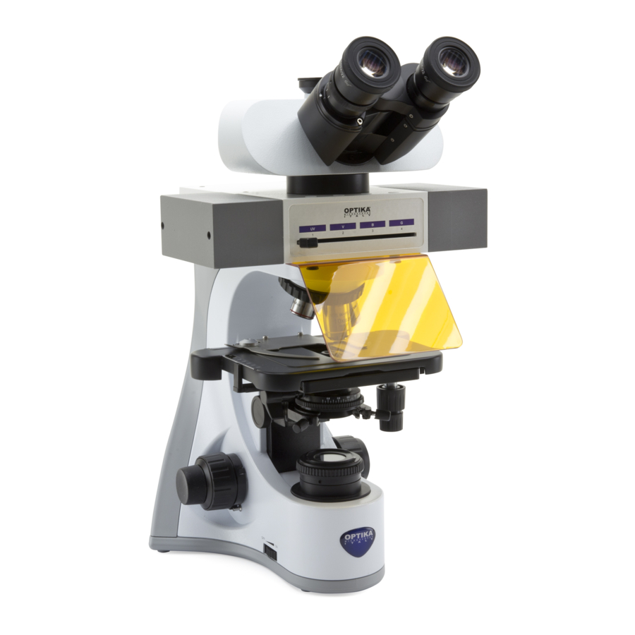
- Page 4 5. Descrizione dello strumento USCITA FOTO/TV GHIERA DI TESTA DI REGOLAZIONE OSSERVAZIONE ⑧ DIOTTRICA ④ REVOLVER OBIETTIVI MANOPOLA DI REGOLAZIONE ALTEZZA ⑨ CONDENSATORE LEVA DI BLOCCO DI MESSA A FUOCO DIAFRAMMA DI ⑫ CAMPO INTERRUTTORE GENERALE / ① SELETTORE REGOLAZIONE LUMINOSITÀ Pagina 4...
- Page 5 5. Descrizione dello strumento (lato opposto) OCULARI TUBO BINOCULARE ⑦ ② FERMAVETRINI TAVOLINO VITI DI CENTRAGGIO LED DEL CONDENSATORE CONDENSATORE MANOPOLE ③ MANOPOLA MICROMETRICA ⑥ VITI DI CENTRAGGIO ⑩ DEL CONDENSATORE MANOPOLA ⑤ MACROMETRICA CONNETTORE PER CONDENSATORE GHIERA DI REGOLAZIONE CAMPO SCURO DELLA TENSIONE Pagina 5...
- Page 6 6. Disimballaggio Il microscopio è riposto in un imballo di polistirolo espanso. Rimuovere il nastro adesivo dal collo ed aprire la parte superiore dell’imballo. Fare attenzione a non far cadere le parti ottiche (obiettivi e oculari) nell’estrarre il microscopio dalla scatola per evitare che vengano danneggiati. Utilizzare entrambe le mani (una intorno allo stativo e una alla base), sfilare il microscopio dal contenitore e appoggiarlo su un piano stabile.
- Page 7 Procedura di montaggio 1. Inserire la testata ottica al di sopra dello stativo e stringere la vite di bloccaggio con la brugola in dotazione. (Fig.1) ► Tenere sempre la testata con una mano durante il serraggio della vite per evitare che la stessa cada. Fig.1 2.
- Page 8 ► Il microscopio viene fornito con due condensatori: uno per campo chiaro ed uno per campo scuro. Selezionare il condensatore adeguato alla metodica di osservazione desiderata. ① 5. Abbassare il supporto portacondensatore agendo sulla vite di regolazione di altezza ①. (Fig. 5) Fig.5 6.
- Page 9 8. Sommario delle procedure di osservazione in campo chiaro (Comandi usati ) (Pag.) Portare su “ON” l’interruttore generale e regolare l’intensità ① Interruttore generale / (pag. 11) luminosa. selettore regolazione intensità ② Fermavetrini (pag. 11) Porre un preparato sul tavolino. ③...
- Page 10 9. Sommario delle procedure di osservazione in campo scuro (Comandi usati ) (Pag.) Portare su “ON” l’interruttore generale e regolare l’intensità ① Interruttore generale / (pag. 11) luminosa. selettore regolazione intensità ② Fermavetrini (pag. 11) Porre un preparato sul tavolino. (pag.
- Page 11 10. Uso del microscopio ① 1. Regolazione dell’intensità luminosa Agire sulla rotellina di regolazione dell’intensità luminosa per accendere e spegnere lo strumento e per aumentare o diminuire il voltaggio dell’illuminazione ①. (Fig.5) 2. Regolazione della frizione della manopola macrometrica (Fig. 6) Regolare la frizione della manopola ►...
- Page 12 5. Compensazione diottrica (Fig. 9) ① Osservare e mettere a fuoco il preparato guardando con l’occhio destro attraverso l’oculare destro utilizzando le manopole di messa a fuoco del microscopio. Ora guardare attraverso l’oculare sinistro con l’occhio sinistro. Se l’immagine non è...
- Page 13 8. Centraggio del condensatore per campo chiaro (Fig.13) Posizionare il campione sul tavolino, inserire l’obiettivo 10x nel percorso ottico e mettere a fuoco. Inserire nel percorso ottico la lente frontale del condensatore swing-out ①. Ruotare la ghiera del diaframma di ④...
- Page 14 11. Microscopia in campo scuro Il B-510DK è un microscopio per osservazione in campo scuro specifico per l’analisi del sangue con uno speciale condensatore per campo scuro extra efficiente, con A.N. da 1,36 a 1,25 e un obiettivo plan acromatico da 100x con diaframma regolabile.
- Page 15 Un fattore che viene comunemente trascurato quando si usano obiettivi ad immersione in olio di apertura numerica aumentata sono le limitazioni poste sul sistema dal condensatore. Lente Frontale In una situazione in cui un obiettivo ad olio di NA = Obiettivo Olio da Immersione 1.40 viene utilizzato per l’immagine di un campione...
- Page 16 11.2 Principi di illuminazione in campo scuro Questo principio viene applicato nella microscopia campo Luce agli Oculari scuro, un metodo semplice e popolare per rendere chiaramente Obiettivo ad visibili oggetti non colorati. Tali oggetti hanno spesso indici di rifrazione molto vicini a quelli Alta Apertura dei loro dintorni e sono difficili da immaginare nella microscopia Numerica...
- Page 17 11.3 Microscopia in campo scuro ad alto ingrandimento Per lavori più precisi e sfondi più scuri, è possibile scegliere un condensatore progettato appositamente per il campo oscuro, ovvero per trasmettere solo raggi obliqui. Esistono diverse varietà: condensatori a campo scuro “a secco” con aria tra la parte superiore del condensatore e la parte inferiore del vetrino e condensatori a campo oscuro a immersione che richiedono l’uso di una goccia di olio per immersione (alcuni invece sono progettati per utilizzare l’acqua) che stabilisce il contatto tra la parte superiore del condensatore e la parte inferiore del vetrino del campione.
- Page 18 1. Centraggio del condensatore per campo scuro Selezionare un campione per campo scuro e posizionarlo sul tavolino del microscopio tra l’obiettivo e il condensatore, inserire l’obiettivo 10x nel percorso ottico e mettere a fuoco. ► Il condensatore proietterà un punto luminoso sul campione che può...
- Page 19 Riposizionare il vetrino e alzare il condensatore fino a che l’olio sulla lente forntale del condensatore non sia a contatto con il vetrino. Posizionare l’area da osservare al centro del percorso ottico usando un obiettivo a basso ingrandimento (10x o 40x). Mettere a fuoco il campione.
- Page 20 11. Ottimizzare il centraggio del condensatore agendo sulla manopola di regolazione di altezza del condensatore e sulle viti di centraggio del condensatore ① e del LED ②. (Fig.27) 12. Dopo avere effettuato il centraggio ottimale del condensatore, rimuovere il telescopio di centramento e riposizionare l’oculare.
- Page 21 12. Microfotografia Installazione dell’adattatore passo “C” 1. Allentare la vite di bloccaggio ① sul tubo trinoculare e rimuovere il tappo antipolvere ② ② ②. (Fig.31) 2. Avvitare l’adattatore passo C ③ alla telecamera installare l’attacco ④ ① ① rotondo del passo C nel foro vuoto del tubo trinoculare, quindi riavvitare la vite di serraggio ①.
- Page 22 13. Manutenzione Ambiente di lavoro Si consiglia di utilizzare il microscopio in un ambiente pulito e secco, privo di urti, ad una temperatura fra 0°C e 40°C e con una umidità relativa massima dell’85% (in assenza di condensazione). Si consiglia l’uso di un deumidificatore se necessario.
- Page 23 14. Guida alla risoluzione dei problemi Consultare le informazioni riportate nella tabella seguente per risolvere eventuali problemi operativi. PROBLEMA CAUSA SOLUZIONE I. Sezione Ottica: L’illuminazione è accesa ma il I connettori dell’alimentatore non sono Collegarli campo visivo è scuro. ben collegati La luminosità...
- Page 24 II. Sezione Meccanica: La manopola macrometrica è difficile L’anello di regolazione della Allentare l’anello di regolazione della ten- da ruotare tensione è troppo stretto sione La messa a fuoco è instabile L’anello di regolazione della Stringere l’anello di regolazione della ten- tensione è...
- Page 25 Smaltimento Ai sensi dell’articolo 13 del decreto legislativo 25 luglio 2005 n°151. “Attuazione delle direttive 2002/95/CE, 2002/96/CE e 2003/108/CE, relative alla riduzione dell’uso di sostanze pericolose nelle apparecchiature elettriche ed elettroniche, nonché allo smaltimento dei rifiuti”. Il simbolo del cassonetto riportato sulla apparecchiatura o sulla sua confezione indica che il prodotto alla fine della propria vita utile deve essere raccolto separatamente degli altri rifiuti.
- Page 27 B-510 Series INSTRUCTION MANUAL Model B-510DK v 1.0 2018...
-
Page 28: Table Of Contents
Table of Contents 1. Warning 2. Symbols and conventions 3. Safety Information 4. Intended use 5. Overview 6. Unpacking 7. Assembling 8. Summary of brightfield observation procedures 9. Summary of darkfield observation procedures 10. Use of the microscope 11. Darkfield microscopy 12. Microphotography 13. Maintenance 14. Troubleshooting Equipment disposal Page 28... -
Page 29: Warning
1. Warning This microscope is a scientific precision instrument designed to last for many years with a minimum of maintenance. It is built to high optical and mechanical standards and to withstand daily use. We remind you that this manual contains important information on safety and maintenance, and that it must therefore be made accessible to the instrument users. -
Page 30: Overview
5. Overview PHOTO/TV PORT DIOPTER OBSERVATION ADJUSTMENT HEAD ⑧ RING ④ NOSEPIECE OBJECTIVE CONDENSER HEIGHT ADJUSTMENT KNOB ⑨ COARSE UPPER LIMIT KNOB FIELD DIAPHRAGM ⑫ MAIN SWITCH / ① BRIGHTNESS ADJUSTMENT KNOB Page 30... - Page 31 5. Overview (opposite side) EYEPIECES BINOCULAR ⑦ TUBE ② SLIDE HOLDER STAGE LED CONDENSER CENTE- RING SCREWS CONDENSER X/Y MOVEMENT ③ KNOBS FINE FOCUS KNOB ⑥ CONDENSER ⑩ CENTERING SCREWS ⑤ COARSE FOCUS KNOB DARK FIELD CONDENSER TENSION ADJUSTMENT RING CONNECTOR Page 31...
-
Page 32: Unpacking
6. Unpacking (B-510DK) The microscope is housed in a moulded Styrofoam container. Remove the tape from the edge of the container and lift the top half of the container. Take some care to avoid that the optical items (objectives and eyepieces) fall out and get damaged. - Page 33 Assembling procedure 1. Insert the optical head above the stand and tighten the screw. (Fig.1) ► Hold the head with one hand during the locking in order to avoid that the head falls. Fig.1 2. Insert both eyepieces into the tubes of the optical head.
- Page 34 ► The microscope is delivered with two condensers: one for brightfield and one for darkfield. Select the suitable condenser forthe observation mode desired. 5. Lower the condenser holder using the ① height condenser knob ①. (Fig. 5) Fig.5 6. Insert the condenser round dovetail with the condeser holder. (Fig. 6) Fig.6 Fig.6 7.
-
Page 35: Summary Of Brightfield Observation Procedures
8. Summary of brightfield observation procedures (Used commands) (Pag.) Set the main swith to “ON” and adjust light intensity.. ① Main switch / (pag. 37) brightness adjustment knob ② Slide holder (pag. 37) Place a slide on the stage. (pag. 31) ③ X/Y movement knobs (pag. -
Page 36: Summary Of Darkfield Observation Procedures
9. Summary of darkfield observation procedures (Used commands) (Pag.) Set the main swith to “ON” and adjust light intensity. ① Main switch / (pag. 37) brightness adjustment knob ② Slide holder (pag. 37) Place a slide on the stage. (pag. 31) ③ X/Y movement knobs (pag. -
Page 37: Use Of The Microscope
9. Use of the microscope ① 1. Light intensity adjustment Operate on the light intensity adjustment knob to turn ON / OFF the microscope and to increase / decrease the illumination voltage ①. (Fig.5) Fig.5 2. Coarse focus tension adjustment ►... - Page 38 5. Dioptric adjustment (Fig. 9) ① Look into the right eyepiece with your right eye only, and focus on the specimen. Look into the left eyepiece with your left eye only. If the image is not sharp, use the dioptric adjustment ring ① to compensate. (Fig.9) ► The adjustment range is ±5 diopter. The number indicated on the adjustment...
- Page 39 8. Centering the condenser (Fig.13) Place the specimen on the stage, insert 10x objective into the light path and focus. Insert the front lens of the swing-out condenser ①. Rotate the field diaphragm ring ② in the direction showed by the arrow, to fully ④...
-
Page 40: Darkfield Microscopy
11. Darkfield microscopy B-5100DK is a darkfield system specific for blood analysis with a 1.36 - 1.25 N.A. special extra efficient darkfield condenser and a 100X plan-achromatic objective with adjustable iris diaphragm. The X-LED illumination ensures the high level of light intensity typically needed in high magnification darkfield techniques. In order to correctly use this microscope, one has to gain some familiarity with: a) oil immersion technique b) darkfield technique. - Page 41 A factor that is commonly overlooked when using oil immersion objectives of increased numerical aperture is limitations placed on the system by the substage condenser. Objective Front Lens In a situation where an oil objective of NA = 1.40 Immersion Oil is being used to image a specimen with a substa- ge condenser of smaller numerical aperture (1.0 Cover Slip...
- Page 42 11.2 Principles of darkfield illumination Darkfield microscopy is a specialized illumination technique Light to that capitalizes on oblique illumination to enhance contrast in Eyepieces High specimens that are not imaged well under normal brightfield il- lumination conditions. Numerical Aperture All of us are quite familiar with the appearance and visibility Objective of stars on a dark night, this despite their enormous distances from the earth.
- Page 43 11.3 High magnification darkfield microscopy For more precise work and blacker backgrounds, you may choose a condenser designed especially for darkfield, i.e. to transmit only oblique rays. There are several varieties: “dry” darkfield condensers with air between the top of the condenser and the underside of the slide–and immersion darkfield condensers which require the use of a drop of immersion oil (some are designed to use water instead) establishing contact between the top of the condenser and the underside of the speci- men slide.
- Page 44 1. Centering of darkfield condenser Select a darkfield specimen and place it onto the microscope stage between the objective and the condenser, insert 10x objective in the light path and focus the specimen. ► The condenser will project a spot of light onto the sample that can be used for centering the optical path..
- Page 45 Reposition the slide and raise the condenser until the oil on the lens of the condenser is in contact with the slide. Move the area to be observed at the center of the optical path using a low magnification objective (10x or 40x). Focus the specimen.
- Page 46 11. Fine adjust the condenser centering using the condenser height adjustment knob, on the condenser ① and LED ② centering screws. (Fig.27) 12. After properly setting the condenser, remove the centering telescope and insert again the eyepiece. Now begin the observation.
-
Page 47: Microphotography
11. Microphotography Installing the C-mount adapter 1. Loosen the clamping screw ① on the trinocular port and remove the dust cap ②. (Fig.27) ② ② 2. Screw the C-mount adapter ③ to the camera ④ and insert the round dovetail ①... -
Page 48: Maintenance
17. Maintenance Microscopy environment This microscope is recommended to be used in a clean, dry and shock free environment with a temperature of 5°-40°C and a maximum relative humidity of 75 % (non condensing). Use a dehumidifier if needed. To think about when and after using the microscope •... -
Page 49: Troubleshooting
18. Troubleshooting Review the information in the table below to troubleshoot operating problems. PROBLEM CAUSE SOLUTION I. Optical Section: LED operates, but field of view re- Power supply is unplugged. Connect mains dark. Brightness is too low Set brightness to a proper level Field of view is obscured or not Revolving nosepiece is not cor- Make sure that the revolving nosepiece... - Page 50 II. Mechanical Section: Coarse focus knob is hard to turn Tension adjustment ring is too Loosen tension adjustment ring tight Focus is unstable Tension adjustment ring is too Tighten tension adjustment ring loose III. Electrical Section LED doesn’t turn on. Power supply not connected Check for proper connection Brightness is not enough...
-
Page 51: Equipment Disposal
Equipment disposal Art.13 Dlsg 25 july 2005 N°151. “According to directives 2002/95/EC, 2002/96/EC and 2003/108/EC relating to the reduction in the use of hazardous substances in electrical and electronic equipment and waste disposal.” The basket symbol on equipment or on its box indicates that the product at the end of its useful life should be collected separately from other waste. - Page 52 OPTIKA S.r.l. ® Via Rigla, 30 - 24010 Ponteranica (BG) - ITALIA Tel.: +39 035.571.392 - Fax: +39 035.571.435 info@optikamicroscopes.com - www.optikamicroscopes.com OPTIKA Spain spain@optikamicroscopes.com OPTIKA USA usa@optikamicroscopes.com OPTIKA China china@optikamicroscopes.com OPTIKA Hungary hungary@optikamicroscopes.com OPTIKA India india@optikamicroscopes.com...
Need help?
Do you have a question about the B-510 Series and is the answer not in the manual?
Questions and answers