Advertisement
Quick Links
PARTS LIST
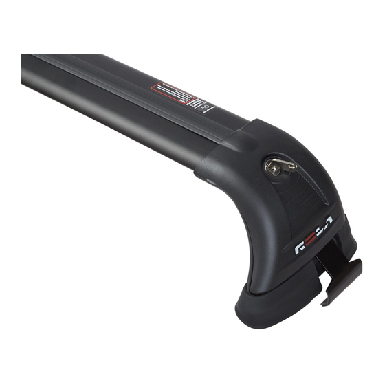
- 1 x CROSSBAR ASSEMBLY
INCLUDING:
1 x CROSSBAR, 2 x END SUPPORTS
1 x BUFFER STRIP, 2 x HINGES
- 1 x KIT OF 2 RUBBER PADS
- 1 x KIT OF 2 COVERS & LOCKS
- 1 x KIT OF STRAPS AND HARDWARE
NOTE: STRAP IMAGES ARE ONLY
REPRESENTATIONS OF ITEMS.
ACTUAL STRAPS COULD LOOK DIFFERENT.
Front Right
No Notches
Fitting Strap inside End Support
Prior to Assembly, check that your Roof Rack Box contains all
the parts as listed above. Ensure the vehicle roof is clean and dry.
Please note, that some illustrations depicted in these instructions
are only representative and your items may look different.
Read these Instructions carefully before commencing.
You will need a cutting blade/knife to cut the buffer strip to the
required length (Step 11).
You can use a protective cloth when installing your
racks to protect the vehicle's roof from any dents and scratches.
Ensure straps correspond with mount positions on
the vehicle before installing them into the End Supports.
Use strap "notches" as shown above - to identify the
correct strap corresponding to its mount location.
1.
Feed Strap neck through cavity in End Support (Fig 1a).
When Strap neck has been pushed through (1), rotate strap
downwards (2) until mount holes in end support and cage nut
inside the strap are aligned.
2.
Use Assembly 'L' Key to feed bolt into strap cage-nut.
Bolt Head should mate flush with its mount face. (Fig 1b)
3.
When threading the bolt through the cage-nut, ensure to
allow a gap of approx. 24mm from the top of the strap neck to
the bolt mount face. (Fig 1c.)
This will aid with the fitment as described in Fig 2c.
Placement of End Support onto Vehicle Roof
4. The Pads all have a vehicle roof position
identification text on the top inside surface,
NOTE: As seen from the driver's position.
Front Right, Front Left,
Rear Right, Rear Left.
Ensure Mount Pads correspond with
mount positions on the vehicle.
Kit may look different than illustration.
5. Using the vehicle's B Pillar as a guide,
place the pads as specified in Fig 2a & 2b.
The pads should be a total of 700mm apart.
Issue A
GTX007R-1F-FI
13/07/09
GTX REMOVABLE Series Roof Racks
Ford FG Falcon Sedan
05/08 - on
Front Left
1 Notch
Fig 2a.
Roof
Your Pad
Channel
Strip
NOTE: RUBBER PAD IMAGES ARE ONLY
REPRESENTATIONS OF ITEMS.
ACTUAL PADS SET COULD LOOK DIFFERENT.
Fig 1a.
2
1
Front of vehicle
Front Right
Fig 2b.
Pad Shown.
GTX007R-1F
CARRYING CAPACITY
Fig 1b.
M6 X 50mm
STAR-HEAD SCREW
TIP: Pull buffer strip
back ~40mm inside
the cross-bar to allow
good access for
Assembly "L" Key to
fit into bolt head.
This will assist when
fastening items
together.
TOP STRAP
Ensure bolt
is constrained
at these points.
(top & bottom)
245mm
page 1 of 2
30 kgs
Front
Fig 3b.
Advertisement

Related Manuals for Rola GTX REMOVABLE Series


Summary of Contents for Rola GTX REMOVABLE Series
- Page 1 GTX REMOVABLE Series Roof Racks GTX007R-1F Ford FG Falcon Sedan CARRYING CAPACITY 30 kgs 05/08 - on PARTS LIST - 1 x CROSSBAR ASSEMBLY INCLUDING: 1 x CROSSBAR, 2 x END SUPPORTS 1 x BUFFER STRIP, 2 x HINGES - 1 x KIT OF 2 RUBBER PADS - 1 x KIT OF 2 COVERS &...
- Page 2 Roof Rack, or the non-observance of the fitting and care instructions. For full warranty information, visit our website: www.rola.com.au page 2 of 2...
Need help?
Do you have a question about the GTX REMOVABLE Series and is the answer not in the manual?
Questions and answers