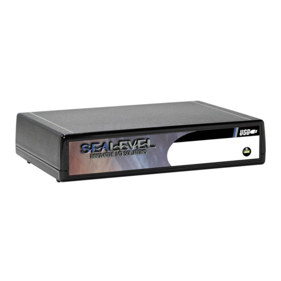
Summary of Contents for SeaLevel SeaLINK PIO-96
- Page 1 SeaLINK PIO-96 User Manual Part Number 8205 www.sealevel.com 155 Technology Place Liberty, SC 29657 864.843.4343...
-
Page 2: Table Of Contents
EADER ONNECTORS ELECTRICAL CHARACTERISTICS ..................10 ......................... 10 PECIFICATIONS EXAMPLE CIRCUITS ......................11 PROGRAMMING THE SEALINK PIO-96 ................12 ......................12 AMPLES AND TILITIES APPENDIX A - TROUBLESHOOTING ................. 13 APPENDIX B – CONNECTOR LOCATIONS – 8205 PCB ..........14 APPENDIX C - COMPLIANCE NOTICES................ -
Page 3: Introduction
(SSRs) for high-power AC or DC loads. The SeaLINK PIO-96’s 96 digital I/O channels are accessed via four 50-pin header connectors with industry-standard pin out. Each header provides 24 bits of digital I/O divided into three eight-bit groups. Each eight-bit group may be individually configured via software command as input or output to best match your particular application requirements. -
Page 4: Before You Get Started
Before You Get Started What’s Included The SeaLINK PIO-96 is shipped with the following items. If any of these items is missing or damaged please contact Sealevel for replacement. SeaLINK PIO-96 Module Sealevel SeaI/O Software CD 5V Power Supply USB Cable for Connecting SeaLINK PIO-96 to Host... -
Page 5: For High-Current, High-Voltage Applications
For high-current, high-voltage applications: IDC 50 to IDC 50 Pin Ribbon Cable (Part Number CA167) 40” cable connects the SeaLINK PIO-96 to solid-state relay racks − equipped with 50-pin header interface. IDC 50 to IDC 50 Pin Ribbon Cable (Part Number CA135) 40”... -
Page 6: Other General Purpose Accessories
Other General Purpose Accessories Din rail mounting clips (Part Number DR102) 2U rackmount tray with clamp. (Part Number RT200KT) 7-port USB hub. (Part Number BF-700) 4-port USB hub. (Part Number BF-400) © Sealevel Systems, Inc. - 6 - SeaLINK PIO-96 User Manual... -
Page 7: Software Installation
Software Installation Windows 98/ME/2000/XP Installation Important: Do not connect the SeaLINK PIO-96 adapter to the host USB device until the software has been fully installed. 1. Start Windows. 2. Insert the Sealevel Systems CD in to your CD drive. 3. If ‘Auto-Start’ is enabled for this drive the software will automatically launch. -
Page 8: Physical Installation
Physical Installation Once you have completed installing the software driver simply connect the SeaLINK PIO-96 to your USB port with the supplied cable. Next connect the DC power input from the AC adapter. The software drivers installed during setup will automatically recognize and configure the device. -
Page 9: Digital I/O Interface
50-pin Header Connectors You will need to open the SeaLINK PIO-96’s enclosure to access the four header connectors P2, P3, P4, and P5 (see Appendix B for connector locations). To open, remove the four screws found on the bottom panel of the unit. Once cables are connected to the headers reassemble the enclosure with the cables exiting the opening on the back panel of the unit. -
Page 10: Electrical Characteristics
Electrical Characteristics The SeaLINK PIO-96 uses 74ABT245 octal bi-directional transceivers to provide TTL input/output capabilities. Each bit is pulled to +5V through a 10K ohm pull-up resistor to insure each bit is at a known state when not driven. Specifications... -
Page 11: Example Circuits
Example Circuits © Sealevel Systems, Inc. - 11 - SeaLINK PIO-96 User Manual... -
Page 12: Programming The Sealink Pio-96
Sealevel’s SeaI/O software is provided to assist in the development of reliable applications for the Sealevel Systems family of digital I/O adapters. Included on the SeaI/O CD are driver functions for use in accessing the I/O as well as helpful samples and utilities. -
Page 13: Appendix A - Troubleshooting
4. Use the SeaIO Control Panel applet or the Device Manager’s property page for card identification and configuration. 5. If these steps do not solve your problem, please call Sealevel Systems’ Technical Support, (864) 843-4343. Our technical support is free and available from 8:00AM- 5PM Eastern Time Monday through Friday. -
Page 14: Appendix B - Connector Locations - 8205 Pcb
Appendix B – Connector Locations – 8205 PCB © Sealevel Systems, Inc. - 14 - SeaLINK PIO-96 User Manual... -
Page 15: Appendix C - Compliance Notices
Always use cabling provided with this product if possible. If no cable is provided or if an alternate cable is required, use high quality shielded cabling to maintain compliance with FCC/EMC directives. © Sealevel Systems, Inc. - 15 - SeaLINK PIO-96 User Manual... -
Page 16: Warranty
(RMA) number. The Customer agrees to insure the Product or assume the risk of loss or damage in transit, to prepay shipping charges to Sealevel, and to use the original shipping container or equivalent. Warranty is valid only for original purchaser and is not transferable.


Need help?
Do you have a question about the SeaLINK PIO-96 and is the answer not in the manual?
Questions and answers