
Related Manuals for Sensia CLIF MOCK CD-20


Summary of Contents for Sensia CLIF MOCK CD-20
- Page 1 C LI F MO CK ™ CD-20 Sample Probe Controller User Manual Class I Groups C and D Manual No. 2350752-01, Rev. 02 Hazardous Locations...
-
Page 2: Important Safety Information
Important Safety Information Symbols and Terms Used in this Manual WARNING: This symbol identifies information about practices or circumstances that can lead to per- sonal injury or death, property damage, or economic loss. CAUTION: Indicates actions or procedures which if not performed correctly may lead to personal injury or incorrect function of the instrument or connected equipment. -
Page 3: Table Of Contents
CD-20 Sample Probe Controller Table of Contents Contents Important Safety Information ..........................ii Section 1—Overview ............................5 How It Works ..............................6 Hazardous Location Safety Compliance ...................... 6 Table 1.1—CD-20 Specifications ......................... 7 Section 2—Installation and Wiring........................7 Section 3—Maintenance ............................ 9 Operational Test ............................ - Page 4 Table of Contents CD-20 Sample Probe Controller...
-
Page 5: Section 1-Overview
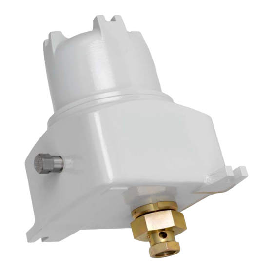
CD-20 Sample Probe Controller Section 1—Overview The CD-20 Sample Probe Controller is engineered for use with the True-Cut C-Series sample probe. It provides both pulse input (flow proportional) and repeat (time proportional) control of the sample probe. When a “start” pulse is received, the probe is rotated to capture and discharge a 1.5-ml isokinetic sample. When installed in a horizontal line, the probe is stopped in the closed position, while on a vertical line the probe is stopped in the open position. -
Page 6: How It Works
CD-20 Sample Probe Controller The motor control assembly (Figure 1.2) consists of a control card and power board mounted to a ring, which in turn, is mounted to the back of the CD-20 gear motor. All field connections are to terminal block 1TB on the control card. -
Page 7: Section 2-Installation And Wiring
CD-20 Sample Probe Controller Table 1.1—CD-20 Specifications 24 VDC 115/230 VAC Temperature -40ºC to 55ºC -40ºC to 55ºC Voltage 24VDC @2A max 115 / 230 VAC @ 1A max Pulse Input 12VDC 12VDC Transistor Output 12VDC max @ 100mA max 12VDC max @ 100mA max Current Draw (Controller) 30 mA... - Page 8 CD-20 Sample Probe Controller Note The input pulse contact must be closed for at least 5 msec to produce a start pulse. An electronic square wave input must have a pulse amplitude of 12VDC. A 5VDC square wave will not work. 1TB-9 = Transistor Output (Emitter) ( ) 1TB-8 = Transistor Output (Collector) (+) 1TB-7 = +12VDC Output...
-
Page 9: Section 3-Maintenance
CD-20 Sample Probe Controller PROX “Hold” LED Repeat time potentiometer I-Limit LED W1 jumper: transistor is OFF when the proximity switch is opposite the high point on the cam. W2 jumper: transistor is ON when the proximity switch is opposite the high point on the cam. -
Page 10: Repeat Mode (Time-Proportional) Check-Out
CD-20 Sample Probe Controller Repeat Mode (Time-Proportional) Check-Out The repeat time potentiometer (Figure 2.3), which determines the rate of sampling when the controller is connected to a probe, is typically set at the factory at 15 seconds. However, it can be adjusted over a range of 3 seconds to 3 minutes. -
Page 11: Motor Control Assembly
CD-20 Sample Probe Controller 5. Reconnect input power to the CD-20. 6. Hold a 100-ml graduated beaker (or other applicable measuring device) under the probe’s discharge. 7. Activate the switch repeatedly to collect 10 samples, 1.5 cc each. Motor Control Assembly The CD-20 motor control assembly (Figure 1.2, page 6) consists of a control card and power board... - Page 12 CD-20 Sample Probe Controller Table 3.1—Troubleshooting Tips for 12VDC/24VDC Controllers Problem Probable Cause Recommended Action Input power fuse F1 open. Input power surge above 33VDC. Check fuse F1. Replace as required. Short circuit on the power board. Return to factory for replacement of power board.
- Page 13 CD-20 Sample Probe Controller Table 3.2—Troubleshooting Tips for 115VAC/230VAC Controllers Problem Probable Cause Recommended Action Input power fuse F1 is open. Input power surge above Check fuse F1. Replace as required. 250VAC. Transformer T1 has an internal Return to factory for replacement of T1 secondary winding or primary or power board.
-
Page 14: Factory Repairs
CD-20 Sample Probe Controller Factory Repairs Important The UL Listing mark applies to the CD Series controller in its original factory condition. To maintain certification, repairs must be performed by a UL-authorized Cameron facility. Attempts to modify the product at any other location will make the certification invalid. To return a product for repair, contact Cameron to request an Return to Manufacturer Authorization (RMA) form and shipping instructions. - Page 15 CD-20 Sample Probe Controller WARRANTY - LIMITATION OF LIABILITY: Seller warrants only title to the products, software, supplies and materials and that, except as to software, the same are free from defects in workmanship and materials for a period of one (1) year from the date of delivery. Seller does not warranty that software is free from error or that software will run in an uninterrupted fashion.
Need help?
Do you have a question about the CLIF MOCK CD-20 and is the answer not in the manual?
Questions and answers