Subscribe to Our Youtube Channel
Summary of Contents for Sensia CLIF MOCK CD-20A
- Page 1 C LI F MO CK ™ CD-20A Sample Probe Controller User Manual Class I Groups C and D Hazardous Locations Manual No. 2350753-01, Rev. 02...
-
Page 2: Important Safety Information
Technical Support Contact Information Global headquarters: Sensia LLC 200 Westlake Park Blvd Houston, TX 77079 Clif Mock is a trademark of Sensia All Rights Reserved. Printed in the United States of America. Manual No. 2350753-01, Rev. 02 September 2013... -
Page 3: Table Of Contents
CD-20A Sample Probe Controller Contents Important Safety Information ..........................ii Section 1—Overview ............................5 How It Works ..............................6 Pulse Input Scaling ............................6 Table 1.1—Pulse Input Switch Setting Examples ..................6 Repeat Time Scaling ............................ 7 Table 1.2—Repeat Time Switch Setting Examples ..................7 Hazardous Location Safety Compliance ...................... - Page 4 Table of Contents CD-20A Sample Probe Controller...
-
Page 5: Section 1-Overview
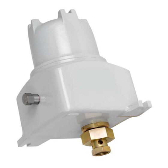
CD-20A Sample Probe Controller Section 1—Overview The CD-20A Sample Probe Controller is engineered for use with the True-Cut C-Series sample probe. It provides both pulse input (flow proportional) and repeat (time proportional) control of the sample probe. When a “start” pulse is received, the probe is rotated to capture and discharge an isokinetic sample. When installed in a horizontal line, the probe is stopped in the closed position, while on a vertical line the probe is stopped in the open position. -
Page 6: How It Works
CD-20A Sample Probe Controller The motor control assembly (Figure 1.2) consists of a control card and power board mounted to a ring, which in turn, is mounted to the back of the CD-20A gear motor. All field connections are to terminal block 1TB on the control card. -
Page 7: Repeat Time Scaling
CD-20A Sample Probe Controller Repeat Time Scaling The repeat mode utilizes a 1-Hz clock signal in lieu of the external flow proportional pulses to pace the sample probe. The X1000, X100, X10, and X1 switches allow direct repeat time settings in seconds (see below). -
Page 8: Section 2-Installation And Wiring
CD-20A Sample Probe Controller Section 2—Installation and Wiring WARNING: This module is designed for connection to hazardous electric voltages. Ignoring this warning can result in severe personal injury or mechanical damage. This product must be reliably earthed and installed by qualified personnel in accordance with the prevailing local electrical wiring regulations and safety standards. -
Page 9: Section 3-Maintenance
CD-20A Sample Probe Controller Jumper required for input flow rates up to 10 Hz; remove jumper for rates of 10 to 1000 Hz 1TB-8 12VDC Output X1000 Switch 1TB-7 Filter 1TB-6 Pulse Input (Emitter) ( ) X100 Switch 1TB-5 Pulse Input (Collector (+) X10 Switch 1TB-4 (Repeat) E1 jumper... -
Page 10: Repeat Mode (Time-Proportional) Check-Out
CD-20A Sample Probe Controller Repeat Mode (Time-Proportional) Check-Out To perform the repeat mode check-out, 1. Connect jumper E1 to terminal 1TB-4 (Figure 2.2, page 2. Set the X10 switch to “6” and set the X1 switch to “0” to set a 60-second repeat time. 3. -
Page 11: Motor Control Assembly
CD-20A Sample Probe Controller 4. Verify that the product line is full and pressurized. 5. Reconnect input power to the CD-20A. 6. Hold a 100-ml graduated beaker (or other applicable measuring device) under the probe’s discharge. 7. Activate the switch repeatedly to collect 10 samples, 1.5 cc each. Motor Control Assembly The CD-20A motor control assembly consists of a control card and power board mounted to a ring, which in turn, is mounted to the back of the CD-20A gear motor. - Page 12 CD-20A Sample Probe Controller Power Board Functions—12VDC and 24VDC Controllers The 12VDC and 24VDC power boards provide the following functions: • Fuse F1 (2-amp, fast-acting) provides short circuit protection. ZD1, a 33V “crowbar” zener diode, pro- vides over voltage protection for the rest of the circuit. •...
- Page 13 CD-20A Sample Probe Controller Power Board Functions—115VAC and 230VAC Controllers The CD-20A power board provides the following functions: • Fuse F1 (1-amp, type AGC) provides short circuit protection. It will open if there is a short in the primary or secondary of transformer T1. • For 115VAC units, transformer T1 converts the input power to 14 VRMS secondary power when primary jumpers W1 and W2 are nstalled on the power board.
-
Page 14: Factory Repairs
CD-20A Sample Probe Controller Problem Probable Cause Recommended Action Current limit LED is on, the Transistor Q4 or Q2 has failed. Return to factory for replacement of CD- motor is stopped. (cont’d) 20A motor control assembly or power board. Current limit LED is on, motor CD-20A current limit circuit Return to factory for replacement of CD- runs at a slow speed. - Page 15 CD-20A Sample Probe Controller WARRANTY - LIMITATION OF LIABILITY: Seller warrants only title to the products, software, supplies and materials and that, except as to software, the same are free from defects in workmanship and materials for a period of one (1) year from the date of delivery. Seller does not warranty that software is free from error or that software will run in an uninterrupted fashion.


Need help?
Do you have a question about the CLIF MOCK CD-20A and is the answer not in the manual?
Questions and answers