
Related Manuals for Sensia JISKOOT InSpec Sampler


Summary of Contents for Sensia JISKOOT InSpec Sampler
- Page 1 MEASUREMENT JISKOOT™ MEASUREMENT SYSTEMS InSpec Sampler Controller Application Operation Manual Software Version 5.10 - Volume 1 Manual No. H128, Rev. 1...
- Page 2 REVISION HISTORY ISSUER APPROVER DATE 1st Issue ______________________________ NOV-30-2020...
-
Page 3: Table Of Contents
InSpec Sampler Controller Table of Contents SECTION 1: INTRODUCTION ..........................11 INTENDED USE ........................... 11 IDENTIFYING THE PARTS OF THE INSPEC FRONT DISPLAY ............11 1.2.1 FRONT PANEL ........................11 BASIC OPERATION OF THE INSTRUMENT (START, STOP, RESET, MANUAL) ......14 SECTION 2: COMMON SOFTWARE FEATURES .................... - Page 4 InSpec Sampler Controller 2.10.1 GENERATE REPORT ......................35 2.10.2 PRINT ..........................35 2.10.3 DELETE BATCHES......................36 2.10.4 EMAIL ..........................36 2.10.5 LOG SETUP ........................38 2.11 SOFTWARE DESCRIPTION ........................ 38 2.11.1 OPERATING SYSTEM ......................38 2.11.2 FILES ..........................38 SECTION 3: DATA COMMUNICATIONS ......................39 WHAT IS IT? ............................
- Page 5 InSpec Sampler Controller 5.4.1 LOG.TXT ..........................49 5.4.2 LOG.CSV ..........................49 5.4.3 AL_PH.CSV ......................... 49 5.4.4 REPORT.TXT ........................50 5.4.5 REPORT.HTM ........................50 SECTION 6: FTP FILE SYSTEM ACCESS ......................51 SECTION 7: INSITU PROGRAMMING ........................ 52 ....................52 ROGRAMMING FROM THE OOTLOADER 7.1.1 Automatic Software Update via the bootloader.
- Page 6 InSpec Sampler Controller 11.8 (&&, ||, ^^, !) .................... 70 OOLEAN OGICAL PERATORS 11.9 (==, !=, >, <, >=, <=) ................ 70 OOLEAN OMPARISON PERATORS 11.10 B (&, |, ^)........................71 WISE PERATORS 11.11 S (>>, <<) ........................71 HIFT PERATORS 11.12 P ......................
- Page 7 InSpec Sampler Controller SECTION 23: MAKING CONNECTIONS ......................95 23.1 ) ....................95 IELD AND OWER ONNECTIONS 23.2 INPUT POWER ............................ 95 23.2.1 EARTHING REQUIREMENTS .................... 95 23.3 SHIELDED (SCREENED) CABLES ..................... 96 SECTION 24: FIELD CONNECTIONS ......................... 97 24.1 CABLE SCREENS &...
- Page 8 SYMBOLS / SYMBOLES ........................118 APPENDIX A: INSPEC CONTROLLER PANEL CUT-OUT DETAIL ..............120 APPENDIX B: INSTALLATION SEQUENCE (SAFE AREA UNIT) ..............121 APPENDIX C: REMOTE I/O (RIO) CONFIGURATION ..................124 APPENDIX D: PUBLISHER NOTES ........................126 *Mark of Sensia...
- Page 9 InSpec Sampler Controller WARNING! This instrument is designed for connection to hazardous electric voltages. Ignoring this warning can result in severe personal injury or mechanical damage. To avoid the risk of electric shock and fire, the safety instructions of this manual must be observed and the guidelines followed.
- Page 10 InSpec Sampler Controller ATTENTION! Cet instrument est conçu pour la connexion à des tensions électriques dangereuses. Ignorer cet avertissement peut entraîner des blessures graves ou des dommages mécaniques. Pour éviter tout risque de choc électrique et d'incendie, les consignes de sécurité de ce manuel doivent être observées, et les orientations suivies.
-
Page 11: Section 1: Introduction
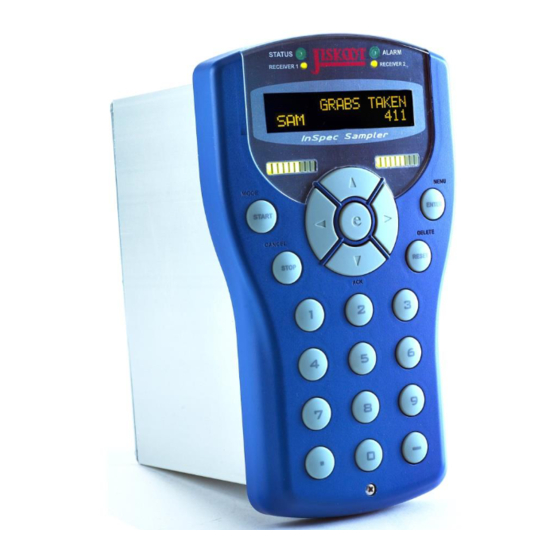
InSpec Sampler Controller SECTION 1: INTRODUCTION SECTION 1: INTRODUCTION INTENDED USE The Jiskoot InSpec is used for Sampling, Blending or Wildstream control applications as determined by the application software installed within it. The controller is not intended to be used as a standalone piece of equipment and must be built- in to the end product and mounted in the vertical plane. - Page 12 SECTION 1: INTRODUCTION InSpec Sampler Controller A brief description of the indicated front display items follows: The Alarm RGB LED indicator. Receiver 2 Tri-Colour LED. The text ‘Receiver’ is specific to the InSpec Sampler Controller. If you have purchased an InSpec Blender Controller this text will state ‘Stream 2’. In either case the LED’s indicate which current sampling can/or blending stream is in use.
- Page 13 InSpec Sampler Controller SECTION 1: INTRODUCTION START. This is the primary function of the button and will be used daily/regularly by operators of the instrument to start a batch/blend. If the instrument is currently running a warning message will appear to tell them a process is currently running. MODE.
-
Page 14: Basic Operation Of The Instrument (Start, Stop, Reset, Manual)
SECTION 1: INTRODUCTION InSpec Sampler Controller BASIC OPERATION OF THE INSTRUMENT (START, STOP, RESET, MANUAL) The Start, Stop and Reset buttons act in their primary function when the menu is closed and showing the front display. This allows a batch or blend to be started, stopped or reset quickly from the front panel. -
Page 15: Section 2: Common Software Features
InSpec Sampler Controller SECTION 2: COMMON SOFTWARE FEATURES SECTION 2: COMMON SOFTWARE FEATURES The Jiskoot InSpec is used for Sampling, Blending and Wildstream control applications. As such, many of the fundamental operating principles are the same regardless of the installed software. This manual will cover the common features of your controller and an additional manual section will cover the application specific software that is currently installed on your unit. - Page 16 SECTION 2: COMMON SOFTWARE FEATURES InSpec Sampler Controller LOGOUT This simply logs out the current user. The only option available then will be the LOGIN USER option described previously above. WHO AM I? This allows quick identification of who is currently logged into the system. It may be useful for various reasons, e.g., if an unattended InSpec is still logged in you can see who previously logged in.
-
Page 17: Navigating The Inspec Display
InSpec Sampler Controller SECTION 2: COMMON SOFTWARE FEATURES NAVIGATING THE INSPEC DISPLAY 2.3.1 BASIC SCREEN LAYOUT The InSpec display consists of a 20x2 LCD display. The display operates within several modes. We will look at each of these briefly. The most common screen that an operator will see during day-to-day use is the front display screen. -
Page 18: Data Entry
SECTION 2: COMMON SOFTWARE FEATURES InSpec Sampler Controller HINT: When you are at either end of a list of options you can use the left or the right button to wrap back around the list. In the above example pressing the left cursor button will take you to option 4 of 4 at the other end of the list. -
Page 19: Alphanumeric Entry
InSpec Sampler Controller SECTION 2: COMMON SOFTWARE FEATURES Selecting the left and right cursor buttons within the existing value will result in the cursor stepping backwards or forwards over existing characters. The up and down cursors can be used within a value to change a specific digit. -
Page 20: Registers
SECTION 2: COMMON SOFTWARE FEATURES InSpec Sampler Controller Figure 8 - Select & Assign Screens REGISTERS A register is a piece of memory that can be thought of as a location containing a single data item of a certain type. The registers are stored in memory that is non-volatile so that when the unit is turned off the contents of the registers remains intact. - Page 21 InSpec Sampler Controller SECTION 2: COMMON SOFTWARE FEATURES Figure 10 - Register Options Menu 2.5.1.1 Set Current Selecting Set current enables an engineer to change the current register value using the data entry methods previously described. 2.5.1.2 Entering Register Values In Engineer Mode A user with engineer level access entering or amending register values will have a different set of characters depending on the register type.
-
Page 22: Display Setup
SECTION 2: COMMON SOFTWARE FEATURES InSpec Sampler Controller 2.5.1.6 View Mod Add The View Mod Add option allows you to view the Modbus address that is assigned to the current register. If no Modbus number is assigned to the register a message will appear to say so. -
Page 23: Bar Graph 1
InSpec Sampler Controller SECTION 2: COMMON SOFTWARE FEATURES Figure 13 - Engineering Display The engineer will have to write down or memorise exactly what variables they have selected for the engineering display to make full use of it. The engineer display options are configured as if they are items 1-6 in the normal operator display with items 1 to 3 on the top line and 4 to 6 on the bottom. -
Page 24: The Alarms Menu
SECTION 2: COMMON SOFTWARE FEATURES InSpec Sampler Controller THE ALARMS MENU Figure 15 - The Alarms Menu The InSpec controller has 60 configurable alarms. For each application (InSpec Sampler or InSpec Blender), there will be a set of default system alarms. These are alarms that are considered very common/useful for the general process. -
Page 25: Set Display Text
InSpec Sampler Controller SECTION 2: COMMON SOFTWARE FEATURES Each of the 60 configurable alarms has a defined name or the alarm is not configured. When a configurable alarm is not configured the title defaults to ‘Empty Slot’. Selecting an empty configurable alarm begins the process of setting up a new alarm. -
Page 26: Email Notification
SECTION 2: COMMON SOFTWARE FEATURES InSpec Sampler Controller 2.7.13 Email notification This decision is asking whether you want a new live occurrence of this alarm to result in email notification. If the answer is yes and an associated alarm is triggered, an email will be sent to the current user as configured in S_MAIL_TO_NAME @ S_MAIL_TO_DOMAIN. -
Page 27: Email Setup
InSpec Sampler Controller SECTION 2: COMMON SOFTWARE FEATURES 2.9.2.2 Date format There are six available date formats. The user can choose from the following options. Note that the first three options allow for the year to be entered in full four-digit format. The latter three options have the year truncated to two digits (i.e., 2006 = 06). -
Page 28: Serial Ports
SECTION 2: COMMON SOFTWARE FEATURES InSpec Sampler Controller Email From Name / Email From Domain & Email To Name / Email To Domain You must enter the “from” and “to” fields for the email. There is no facility to enter the ‘@’... - Page 29 InSpec Sampler Controller SECTION 2: COMMON SOFTWARE FEATURES • Modbus Master –instance of Modbus master must have its own dedicated serial port. The InSpec serial ports are able to run Modbus on either an RS232, RS422 or an RS485. Once Modbus is selected to work on the port the following are standard configuration options when running Modbus over a serial link •...
-
Page 30: Modbus Tcp Slave
SECTION 2: COMMON SOFTWARE FEATURES InSpec Sampler Controller • Port 1 → Display (Not Configurable) • Port 2 → Off • Port 3 → Off 2.9.5 MODBUS TCP SLAVE This menu item allows you to setup Modbus TCP slave. You are prompted for the Modbus string size, the float word order and the long word order. -
Page 31: User Commands
InSpec Sampler Controller SECTION 2: COMMON SOFTWARE FEATURES PRIMARY DNS The Primary DNS server translates domain names meaningful to humans into the numerical identifiers called IP address that are associated with networking equipment for locating and addressing devices worldwide. An often-used analogy to explain the Domain Name System is that it serves as the "phone book"... - Page 32 SECTION 2: COMMON SOFTWARE FEATURES InSpec Sampler Controller 2.9.9 The InSpec IO menu for a Sampler or a Blender consists of 3 sub-menus. Note, this menu is not available on the remote IO InSpec. This is to ensure all calibration and configuration of the IO for a remote device is performed via the menus (Web or front panel) on the master InSpec.
- Page 33 InSpec Sampler Controller SECTION 2: COMMON SOFTWARE FEATURES Figure 22 - The ADC test screen from the IO tests menu The upper line of the display gives the raw value coming in on the ADC channel. The lower line then shows the associated calibrated value scaled for a 4-20mA signal. Use the UP and DOWN buttons to switch between ADC channels 1 to 3.
- Page 34 SECTION 2: COMMON SOFTWARE FEATURES InSpec Sampler Controller Digital Tests The display for both the digital in and out tests shows whether the specific digitals are available for test. In the following two pictures you will see that certain digital inputs or outputs are shown as an X.
-
Page 35: Records And Logs
InSpec Sampler Controller SECTION 2: COMMON SOFTWARE FEATURES Figure 27 - Set 20mA calibration point during ADC calibration routine. Once your input test signal settles, enter the value for the default 4mA calibration point. On doing so you will then be presented with a very similar 20mA screen. To calibrate between 4 and 20ma, the values entered have to be within a given range else a message box will appear stating that the calibration is ‘Invalid’. -
Page 36: Delete Batches
SECTION 2: COMMON SOFTWARE FEATURES InSpec Sampler Controller Note: If the C_AUTO_REPORT register is set, the end of batch report will be printed automatically at the end of a batch. If the SMTP service is configured and the C_AUTO_MAIL_REPORT register is set, then the end of batch will be automatically emailed to the specified recipient. - Page 37 InSpec Sampler Controller SECTION 2: COMMON SOFTWARE FEATURES ALARM PHASE LOG Allows you to navigate the directory structure and select a batch alarm phase log (AL_PH.CSV). The alarm phase log from this folder could then be printed. You will be notified if the alarm phase log file does not exist.
-
Page 38: Log Setup
SECTION 2: COMMON SOFTWARE FEATURES InSpec Sampler Controller AUTO ALARM MAIL Here you set the configuration option to set if a batch alarm phase log is automatically emailed at the end of a batch. BACKUP IMAGE Create an image of the InSpec configuration and email to the specified address. 2.10.5 LOG SETUP The Log is a shared application feature that enables up to 20 data variables to be printed out consecutively in a running log. -
Page 39: Section 3: Data Communications
InSpec Sampler Controller SECTION 3: DATA COMMUNICATIONS SECTION 3: DATA COMMUNICATIONS WHAT IS IT? The purpose of data communications is to transfer information between two or more units. As a rule, it is characters (text or numbers) and/or instructions (commands) that are transmitted. The simplest level of computer language is binary digits where each character is composed of seven to eight binary 1’s or 0’s. -
Page 40: The Right Connection
SECTION 3: DATA COMMUNICATIONS InSpec Sampler Controller THE RIGHT CONNECTION The following is based on a simple RS232 connection. • Two terms that recur in data communications are DTE (Data Terminal Equipment) and DCE (Data Communication Equipment). • Computers and terminals are usually DTE’s, modems and communications hardware are generally DCE’s while other equipment such as multiplexers and printers can be either. -
Page 41: Line Termination And Fail-Safe
InSpec Sampler Controller SECTION 3: DATA COMMUNICATIONS 3.11 RS422 EIA-422 or RS422 is a physical layer electrical specification of a four-wire, full-duplex, point to point or multi-drop serial connection. RS422 is a standard interface that is suitable for industrial applications. It was created for the construction of multi-drop data busses, between a main computer and a number of terminals. -
Page 42: Section 4: Ip Settings
SECTION 4: IP SETTINGS InSpec Sampler Controller SECTION 4: IP SETTINGS As well as providing legacy serial connectivity, the InSpec has an Ethernet port and, if configured correctly, can provide Modbus TCP (Master/Slave), Network Time Protocol (NTP) updates, SMS email notification for alarms, batch reports, log files and diagnostic files etc, Ethernet printing, Telnet sessions and an extensive Web browser interface to configure and monitor the application. -
Page 43: Configure Dhcp
InSpec Sampler Controller SECTION 4: IP SETTINGS 4.1.3 Configure DHCP InSpec Menu Options = DHCP enabled / timeout What is DHCP? DHCP is the Dynamic Host Configuration Protocol, this protocol is used by hosts connected to a network (DHCP clients) to obtain IP address assignments and other configuration information from the server. -
Page 44: Default Gateway
SECTION 4: IP SETTINGS InSpec Sampler Controller The subnet mask is either entered manually via the set static menu option or it is obtained via the DHCP protocol. If DHCP is enabled but fails to provide a subnet mask, the subnet mask will revert to the default static settings. -
Page 45: Smtp Url Address
InSpec Sampler Controller SECTION 4: IP SETTINGS If the primary DNS server fails, a secondary DNS server is often provided as a fall back. If DHCP is enabled the secondary DNS server address should be obtained from the DHCP server. However, you can still enter a static secondary DNS server address. -
Page 46: Network Printer - Default Port = 515
SECTION 4: IP SETTINGS InSpec Sampler Controller 4.3.2 NETWORK PRINTER – DEFAULT PORT = 515 String Register 4 IP Registers S_PRINT_SERVER_URL I_PRINT_IP_ADDR0,I_PRINT_IP_ADDR1,I_PRINT_IP_ADDR2, I_PRINT_IP_ADDR3 4.3.3 NTP TIME – DEFAULT PORT = 123 (UDP/IP PROTOCOL) String Register 4 IP Registers S_NTP_SERVER_URL I_IP_NTP0, I_IP_NTP1, I_IP_NTP2, I_IP_NTP3 4.3.4 MODBUS TCP –... -
Page 47: Section 5: Sd Card File System
InSpec Sampler Controller SECTION 5: SD CARD FILE SYSTEM SECTION 5: SD CARD FILE SYSTEM A secure digital memory card is used in the InSpec to store batch and system data. The InSpec supports the SD format (up to 2Gb. Formatted to FAT16). Please avoid using higher capacity SDHC cards. It is not something we currently recommend due to performance issues. -
Page 48: Csdata
SECTION 5: SD CARD FILE SYSTEM InSpec Sampler Controller 5.3.1 CSDATA This directory contains all the instrument data created by the shell command SAVECS. Where there are the following 4 files. 5.3.1.1 CONFIG.BIN This file contains a binary copy of the instrument FRAM. It is only compatible with software of the same version. -
Page 49: Log.txt
InSpec Sampler Controller SECTION 5: SD CARD FILE SYSTEM The batch name in this path is taken from the S_BATCH_TITLE and S_BATCH_TITLE_NXT registers. The _NXT register is used when setting up the next batch/blend during a current batch/blend. There are similar _NXT registers for all batch/blend parameters. -
Page 50: Report.txt
SECTION 5: SD CARD FILE SYSTEM InSpec Sampler Controller 5.4.4 REPORT.TXT This file and the related report.htm file will not appear until the batch has been reset. Report files are produced for each batch. 5.4.5 REPORT.HTM See report.txt above. This is the HTML version of the report file. -
Page 51: Section 6: Ftp File System Access
InSpec Sampler Controller SECTION 6: FTP FILE SYSTEM ACCESS SECTION 6: FTP FILE SYSTEM ACCESS The entire file system can be accessed from a network using the standard FTP (file transfer protocol), for instance to allowing access to batch logs. FTP has security which is given as, at present this password cannot be changed. -
Page 52: Section 7: Insitu Programming
SECTION 7: INSITU PROGRAMMING InSpec Sampler Controller SECTION 7: INSITU PROGRAMMING Programming from the Bootloader Upon each reboot of the InSpec you will see the following text. InSpec bootloader version 2.04 Press the space key to abort application booting The ‘press the space key’ prompt offers the ability to interrupt the boot sequence to access the bootloader command shell. -
Page 53: Manual Software Update Via The Bootloader
InSpec Sampler Controller SECTION 7: INSITU PROGRAMMING You are offered the option of interrupting this process via the space key. If you skip this option, you will see messages informing you that the flash is being erased (followed by repeated dots). Once this is done you will see a message informing you that the flash is being programmed (followed by repeated dots). -
Page 54: Upgrading Existing Software Via Testcard
SECTION 7: INSITU PROGRAMMING InSpec Sampler Controller The flash re-programming sequence as shown in the Automatic Software Update section now follows. The main difference is that the file is not renamed at the end of the process (it is not necessary) and the application does not automatically boot. -
Page 55: Upgrading - The Upgrade Data Folder
InSpec Sampler Controller SECTION 7: INSITU PROGRAMMING After the application is started you will see further information unique to the UPGRADE task as follows: Erasing FRAM Defaulting registers ............Loading registers and Modbus addresses from prior version ............Upgrade completed Enter username to access shell: After the upgrade is completed the application will start and you will see the usual shell username/password prompt. -
Page 56: Upgrading The Bootloader Software Via The Application
SECTION 7: INSITU PROGRAMMING InSpec Sampler Controller In addition to these files you may also have a file called UPGRADE.LOG This file exists if any registers have not been found between versions during the upgrade. The bad register numbers / names are listed in the upgrade.log file. - Page 57 InSpec Sampler Controller SECTION 7: INSITU PROGRAMMING A successful bootloader re-programming sequence should appear as follows: Erasing flash, ..Flash erased, now Programming,........Verifying flash,..........Completed verification successfully A reboot is now required M:\ TESTCARD$ If anything fails during the reboot process and you are unable to recover and re-program the bootloader then unfortunately the InSpec will need to be returned to the factory.
-
Page 58: Section 8: Sd Card System Files
SECTION 8: SD CARD SYSTEM FILES InSpec Sampler Controller SECTION 8: SD CARD SYSTEM FILES On the SD card there should always be a SYSTEM folder. If it does not exist when the instrument is powered up, then it is created automatically to create the two required report template files (REPORT_TEMPLATE.TXT and REPORT_TEMPLATE.HTM). - Page 59 InSpec Sampler Controller SECTION 8: SD CARD SYSTEM FILES Security Log Entry Associated Content LOGIN Who logged in when and from which serial port. LOGOUT Who logged out when and from which serial port. USER_DELETED Which user was deleted by who, when and from which serial port.
- Page 60 SECTION 8: SD CARD SYSTEM FILES InSpec Sampler Controller PATH /$I_START_YEAR$/$C_START_MONTH$/$C_START_DAY$/$S_BATCH_TITLE$_$L_BATCH_ID$.$ I_TOTAL_BATCH_COUNT$ REPORT ENDS ----------- The report file begins with a series of headings. E.g., “CAMERON JISKOOT QUALITY SYSTEMS”, “SAMPLER COLLECTION REPORT” etc. The first line of the report that is configurable is: $S_REPORT_VARIABLE$ This is a register name between two $ symbols.
-
Page 61: Section 9: Modbus Information
InSpec Sampler Controller SECTION 9: MODBUS INFORMATION SECTION 9: MODBUS INFORMATION General Modbus is a communications protocol designed by Modicon Inc. Industrial Automation Systems. The version supported is that as specified in the Protocol Reference Guide , with extensions for handling 32bit IEEE floating-point numbers, 32bit integers (including alarms) and Strings. -
Page 62: Ascii
SECTION 9: MODBUS INFORMATION InSpec Sampler Controller 9.6.1 ASCII Only the characters 0-9 and A-F are transmitted as data. A ‘:’ is used to start the message, and Carriage Return, Linefeed pair used to terminate it. A delay of 1 second may be tolerated between characters. -
Page 63: Modbus Addresses
InSpec Sampler Controller SECTION 9: MODBUS INFORMATION Function Code (HEX) Read Holding Registers Read Input Registers Pre-set Multiple Registers Modbus Addresses Modbus addresses can be allocated to every register that is required to be accessed as a slave. This can either be accomplished via the register access feature of the menu or configured via the debug port using the RM and WM commands. -
Page 64: Modbus Slave
SECTION 9: MODBUS INFORMATION InSpec Sampler Controller 9.15 Modbus Slave This is the ‘client’ of the master unit. Each slave is given a unique identifier in the range 1 to 247. When in this mode, the slave listens on the appropriate port until a query from a master unit is heard. When the query is received, the slave address is decoded and if it is not the same as the instruments, the packet is ignored. -
Page 65: Section 10: User Commands
InSpec Sampler Controller SECTION 10: USER COMMANDS SECTION 10: USER COMMANDS The InSpec includes a facility to perform a number of simple calculations on registers. These are known as user commands. NOTE: This is only designed to solve simple problems and so more complex problems will require using the programming language UCL. - Page 66 SECTION 10: USER COMMANDS InSpec Sampler Controller Command Supported in Example float destinations MULTIPLY SOURCE1=3, SOURCE2=4 DESTINATION = SOURCE1 SOURCE2 = 3 4 = 12 DIVIDE SOURCE1=12, SOURCE2=3 DESTINATION = SOURCE1 / SOURCE2 = 12 / 3 = 4 SOURCE1=3, SOURCE2=4 DESTINATION = SOURCE1 + SOURCE2 = 3 + 4 = 7 SUBTRACT...
-
Page 67: Section 11: User Configurable Logic (Ucl)
InSpec Sampler Controller SECTION 11: USER CONFIGURABLE LOGIC (UCL) SECTION 11: USER CONFIGURABLE LOGIC (UCL) UCL is a programming language for creating additional logic features in the InSpec controller. It provides the ability to alter register values on a real time basis, according to a set of predefined commands. UCL is a functional language. -
Page 68: What Makes Up Aucl Program
SECTION 11: USER CONFIGURABLE LOGIC (UCL) InSpec Sampler Controller When you first run a UCL program it is advised to run the task in DEBUG mode. To do this, follow these steps. First, we will assume that the UCL.TXT file has been created already. At the terminal type: DEBUG UCL Followed by: START UCL... -
Page 69: Types And Type Casting
InSpec Sampler Controller SECTION 11: USER CONFIGURABLE LOGIC (UCL) Carriage returns and spaces can be included in the file, enabling the programmer to customise the layout. It is suggested that each new statement should be started on a new line to make reading of the program easier. -
Page 70: Arithmetic Operators (+, -, *, /, %)
SECTION 11: USER CONFIGURABLE LOGIC (UCL) InSpec Sampler Controller The value 5.2 must be cast into an int16 type to be stored in the register i_ispare1. In this case, it is cast to the value 5, because I_USER_INT1 is an integer register. Casting of this type always rounds down. -
Page 71: Bit-Wise Operators (&, |, ^)
InSpec Sampler Controller SECTION 11: USER CONFIGURABLE LOGIC (UCL) • < LESS THAN (float < float = boolean) (1 < 2 = TRUE) If left argument is less than right argument, return TRUE, else return FALSE • >= GREATER THAN OR EQUAL TO (float >= float = boolean) (1 >= 1 =TRUE) If left argument is greater than or equal to right argument, return TRUE, else return FALSE. -
Page 72: Pow Example
SECTION 11: USER CONFIGURABLE LOGIC (UCL) InSpec Sampler Controller This produces the natural log for the value of register F_USER_FLOAT1. 11.13.3 POW EXAMPLE F_USER_FLOAT2=POW(F_USER_FLOAT3, F_USER_FLOAT4); This raises F_USER_FLOAT3 to the power F_USER_FLOAT4. These are floating power powers and so can also be used in the calculation of roots, a square root would be to the power 0.5 11.13.4 SIN EXAMPLE F_USER_FLOAT2=SIN(F_USER_FLOAT1);... -
Page 73: Operator Priority And Parenthesising
InSpec Sampler Controller SECTION 11: USER CONFIGURABLE LOGIC (UCL) i_ispare2 = i_ispare2 == 60 ? 0 : i_ispare2 ; This sets up a counter which is incremented every second. When the counter reaches 60, it is then reset back to 0. 11.15 Operator Priority and Parenthesising Operator prioritising means you may occasionally get unexpected results from an equation. - Page 74 SECTION 11: USER CONFIGURABLE LOGIC (UCL) InSpec Sampler Controller If there are mismatching conditional/jump section labels, then the file will fail to compile. The simple premise is that a conditional statement needs to know where the code will jump to (go to) when the conditional equation returns true.
- Page 75 InSpec Sampler Controller SECTION 11: USER CONFIGURABLE LOGIC (UCL) If HORN_OUTPUT_COUNTER less than 21 jump to 3 ALARM_END section of code 3 else HORN_OUTPUT_COUNTER must equal 20. Set ALARM_SOUND_HORN to FALSE, the ALARM_DELAY_COUNTER = 0 and HORN_OUTPUT_COUNTER=0; 3 ALARM_END The UCL File #define ALARM_DELAY_COUNTER = I_USER_INT1;...
-
Page 76: Section 12: Flow Weighted Averaging
SECTION 12: FLOW WEIGHTED AVERAGING InSpec Sampler Controller SECTION 12: FLOW WEIGHTED AVERAGING Flow weighted averaging allows a variable to be averaged on the lifetime of a batch. Correctly averaging it for the flow throughout. The following simple formula is used It should be noted that the variable needs to have a linear relationship to be suitable to be averaged, some linearization calculations maybe needed on variables that are not linear, for example viscosity. -
Page 77: Section 13: Pid Blocks
InSpec Sampler Controller SECTION 13: PID BLOCKS SECTION 13: PID BLOCKS The InSpec has 10 users configurable PID blocks. These are configured via the field menu. The PID block items consists of 2 sub menus: PID Config – Here you are prompted to turn the specific PID block on, enter the source register (PID input), the active phases and whether the PID should jump to a specific value when it goes into a non-active phase. -
Page 78: Section 14: Storing Configuration Backups
SECTION 14: STORING CONFIGURATION BACKUPS InSpec Sampler Controller SECTION 14: STORING CONFIGURATION BACKUPS Backups of the instrument software, registers and configuration files can be easily performed from the InSpec start up system menu to the SD card or, if configured, you can do this from the web interface. Once a configuration has been backed up it can be copied to a PC or server either via the web interface (the easiest option), by moving the SD card to a PC or via an FTP command or application. -
Page 79: Section 15: Restoring Configuration Backups
InSpec Sampler Controller SECTION 15: RESTORING CONFIGURATION BACKUPS SECTION 15: RESTORING CONFIGURATION BACKUPS Backups of the instrument software, registers and configuration files can be easily restored from the InSpec start up system menu or, if configured, you can do this from the web interface. The InSpec system menu is accessed by powering the instrument on while holding down the delete key. -
Page 80: Section 16: System Start Up Menu
SECTION 16: SYSTEM START UP MENU InSpec Sampler Controller SECTION 16: SYSTEM START UP MENU When the unit is switched on for the first time or after new software has been installed the InSpec will boot to the system start-up menu. Alternatively, this menu can be accessed by rebooting the system and holding down the delete/reset key. -
Page 81: Format Sd Card
InSpec Sampler Controller SECTION 16: SYSTEM START UP MENU 16.10 FORMAT SD CARD This item wipes the BBRAM. Any configuration values/settings will be lost as a result. Upon exiting the system menu, the System folder and report template files will be recreated. Note if you format the SD card you will lose all the current users and the InSpec will default back to having just the 3 default users –... -
Page 82: Section 17: Web (Http) Interface
SECTION 17: WEB (HTTP) INTERFACE InSpec Sampler Controller SECTION 17: WEB (HTTP) INTERFACE Each InSpec Controller (Sampler, Blender, Remote IO) comes with a built in alternative web interface that can be viewed by most browsers (e.g., Google Chrome , Mozilla Firefox , Microsoft Internet Explorer which allows the system to be monitored and controlled from a web browser. -
Page 83: Section 18: Svg Schematic - Web Interface
InSpec Sampler Controller SECTION 18: SVG SCHEMATIC - WEB INTERFACE SECTION 18: SVG SCHEMATIC - WEB INTERFACE Figure 32 – The Default Sampler Graphics Page On the status page there is a button labelled graphics. When you click this the graphical schematic will appear. - Page 84 SECTION 18: SVG SCHEMATIC - WEB INTERFACE InSpec Sampler Controller Figure 34 – The Default Blender Streams Graphics Page There are 20 labels for each of the displays. Each label has the following associated internal registers: S_SVG_TITLE1-20 – These registers contain the title that will be displayed for this specific label. P_SVG_DISP1-20 –...
- Page 85 InSpec Sampler Controller SECTION 18: SVG SCHEMATIC - WEB INTERFACE Figure 35 – The Blender Overview Graphic Setup Page Figure 36 – The Blender Stream Graphic Setup Page...
- Page 86 SECTION 18: SVG SCHEMATIC - WEB INTERFACE InSpec Sampler Controller Figure 37 – The Blender ‘Edit Labels’ Setup Page...
-
Page 87: Section 19: Remote Io Module
InSpec Sampler Controller SECTION 19: REMOTE IO MODULE SECTION 19: REMOTE IO MODULE 19.1 FIELD CONNECTIONS See InSpec Remote I/O (RIO) Module manual (H109). 19.2 CONNECT WITH WEB INTERFACE The web page interface of the master InSpec has pages for configuring these remote devices. To configure a device, it must be accessible on the same network. -
Page 88: Remote Adc Device
SECTION 19: REMOTE IO MODULE InSpec Sampler Controller Figure 39 – Remote IO Module (Incorrect IO Device) Figure 40 – Remote IO Module (Connected and Compatible) 19.3 REMOTE ADC DEVICE This page contains the items required to both test and calibrate a Remote ADC module. The ADC table shows the ADC number, the raw integer valve of the ADC, the scale 0 to 1 value of the ADC, the calibration points at 4mA and 20mA, the ADC title, the output scaled value minimum, maximum and resulting scaled value, finally the cal button allows the ADC's to be calibrated. -
Page 89: Remote Dac Device
InSpec Sampler Controller SECTION 19: REMOTE IO MODULE Figure 41 – Remote ADC 0, Option in Menu Sidebar for Setup and Test 19.4 REMOTE DAC DEVICE This page contains the items required to all configure, test and calibrate a Remote DAC module. The DAC table shows the DAC number, the DAC test output in mA, the calibration slope and intercept (ITC), the output source register, the source register minimum and maximum. -
Page 90: Remote Digital Device
SECTION 19: REMOTE IO MODULE InSpec Sampler Controller 19.5 REMOTE DIGITAL DEVICE This page contains the items required to both configure and test a Remote Digital module. The digital outputs can be set to on or off by clicking the ‘ON|OFF’ button or made to toggle automatically by clicking the toggle button. - Page 91 InSpec Sampler Controller SECTION 19: REMOTE IO MODULE...
-
Page 92: Section 20: Remote Io Web Page
SECTION 20: REMOTE IO WEB PAGE InSpec Sampler Controller SECTION 20: REMOTE IO WEB PAGE Each remote IO module has a web page with a similar layout to the Inspec web page. It is a cut down version of this web page with a set of similar menus which can be accessed via clicking the left-hand side menu select buttons. -
Page 93: Section 21: Safety Information
InSpec Sampler Controller SECTION 21: SAFETY INFORMATION SECTION 21: SAFETY INFORMATION Refer to the latest revision of the InSpec Controller Safety Instructions manual (H84). -
Page 94: Section 22: Installation Details
SECTION 22: INSTALLATION DETAILS InSpec Sampler Controller SECTION 22: INSTALLATION DETAILS This instrument is designed for the following: - • Equipment Class I • Installation Categories o AC Power Inlet – Installation Category II o Relay Outputs – Installation Category III •... -
Page 95: Section 23: Making Connections
InSpec Sampler Controller SECTION 23: MAKING CONNECTIONS SECTION 23: MAKING CONNECTIONS 23.1 Field and Power Connections (Rear) There are seven external connectors on the rear of the controller and full descriptions for these are found in the sections that follow: - Plug 5 - Pin 1 Plug 1 - Pin 1 Plug 6 - Pin 1... -
Page 96: Shielded (Screened) Cables
SECTION 23: MAKING CONNECTIONS InSpec Sampler Controller 23.3 SHIELDED (SCREENED) CABLES Any signal or control cable screens and drain wires should be terminated onto a low-impedance earth (ground), preferably using a 360° shield (screen) clamp. If pigtails are used, where the screen is brought down to a single wire and connected to the earth point, then these must be as short as possible;... -
Page 97: Section 24: Field Connections
InSpec Sampler Controller SECTION 24: FIELD CONNECTIONS SECTION 24: FIELD CONNECTIONS SELV Circuits All circuits wired to Plugs 5 & 6 must be connected to SELV circuits. Please refer to section 0 for a definition of SELV circuits Circuits TBTS Tous les circuits câblés aux fiches 5 &... -
Page 98: Plug No. 5
SECTION 24: FIELD CONNECTIONS InSpec Sampler Controller LIVE 24V DC Fuse Fuse AC LOAD DC LOAD NEUTRAL Figure 47 - Connecting a Relay Output 24.3 PLUG NO. 5 IMPORTANT: Cables terminating to this terminal block must be screened. This terminal block is carries connections for Serial Communications (RS232, RS422 & RS485). Its terminal assignments are as follows: - RS232 RS422/485... -
Page 99: Rs422 & Rs485 Termination
InSpec Sampler Controller SECTION 24: FIELD CONNECTIONS 24.3.2 RS422 & RS485 TERMINATION For correct operation of the multi-drop bus, the communication lines must be held in the default fault tolerant position. For RS422 this is done at each receiver and Rx+ is pulled low (0V) and Rx- is pulled high (5V).For RS485 this is done at each transceiver and Tx/Rx+ is pulled low (0V) and Tx/Rx- is pulled high (5V). -
Page 100: Dc Power (1 Off)
SECTION 24: FIELD CONNECTIONS InSpec Sampler Controller follows: - Figure 52 - Plug 6 Connections 24.4.1 24V DC POWER (1 OFF) If the controller is powered via the AC mains connector then these connections supply a fused and regulated 24V DC supply, suitable for powering 4-20mA loops, pulse transmitters, and low power DC resistive devices. -
Page 101: 4-20Ma Analogue Output (2 Off)
InSpec Sampler Controller SECTION 24: FIELD CONNECTIONS Voltage Pulse Signal 24.5 19.5 14.5 -0.5 Time Input Signal Threshold Figure 55 - Voltage and Current Pulse Signals 4-20mA 270R Figure 56 - Connecting a Voltage or Current Pulse Input 24.4.4 4-20mA ANALOGUE OUTPUT (2 off) Each analogue output is a current source, sometimes referred to as a ‘powered’... -
Page 102: Section 25: Instrument Specifications
SECTION 25: INSTRUMENT SPECIFICATIONS InSpec Sampler Controller SECTION 25: INSTRUMENT SPECIFICATIONS 25.1 GENERAL SPECIFICATIONS Design Area Item Description Physical Size (mm) 130 x 220 x 165 (W x H x D) Approx. inc. PE stud Depth including connectors approx. 220mm Weight 1.8 kg Wire Connections... -
Page 103: Insulation Co-Ordination
InSpec Sampler Controller SECTION 25: INSTRUMENT SPECIFICATIONS Accuracy ±0.1% of FSD (12-bit resolution) Output Protection Over Voltage (26VDC TVS) Analogue Inputs Quantity Input Type 4-20mA Accuracy ±0.1% of FSD (12-bit resolution) Input Impedance 50 ohms Input Protection Over Voltage (26VDC TVS) Pulse Inputs Quantity Input Type... -
Page 104: Section 26: Instrument Breakdown
SECTION 26: INSTRUMENT BREAKDOWN InSpec Sampler Controller SECTION 26: INSTRUMENT BREAKDOWN No.1 Pozidriv (cross-head) Screwdriver 2.5mm Hexagon Wrench or Allen Key 4mm Hexagon Wrench or Allen Key 7mm Combination Spanner Modern electronic devices are very sensitive to static electric charges. Use a grounding wrist strap at all times - See section 0 for more details 26.1 DISASSEMBLY The following flowchart provides an overview of dismantling the unit into its component parts, which... -
Page 105: Section 27: Printed Circuit Boards
InSpec Sampler Controller SECTION 27: PRINTED CIRCUIT BOARDS SECTION 27: PRINTED CIRCUIT BOARDS Warning: • Instructions for adjustments while covers are removed and for servicing are for use by service trained personnel only. • To avoid dangerous electric shock, do not perform such adjustments or servicing unless qualified to do so. -
Page 106: Printed Circuit Board Configuration
SECTION 27: PRINTED CIRCUIT BOARDS InSpec Sampler Controller 27.2 PRINTED CIRCUIT BOARD CONFIGURATION 27.2.1 PCB HANDLING PRECAUTIONS Handle electronic components and printed circuit card assemblies only when you are properly grounded in an ESD Protected Area (EPA). You are a source of ESD unless you are grounded properly. -
Page 107: F3174 Configuration
InSpec Sampler Controller SECTION 27: PRINTED CIRCUIT BOARDS 27.3 F3174 CONFIGURATION The figure below shows the location of all the configurable items on the F3174 PCB. SD Card Connector CR 1220 Primary Lithium Cell System Status LEDs Indication dependent upon firmware System Reset Switch Power LED version. -
Page 108: F3175 Configuration
SECTION 27: PRINTED CIRCUIT BOARDS InSpec Sampler Controller 27.4 F3175 CONFIGURATION The figure below shows the location of all the configurable items on the F3175 PCB. Pulse Inputs oltage/C urrent Pulse Configur ation. Pulse Inputs rigger threshold Figure 62 - F3175 Configurable Items adjustmen 27.4.1 SWITCH SETTINGS FOR ‘SW1’... -
Page 109: F3176 Configuration
InSpec Sampler Controller SECTION 27: PRINTED CIRCUIT BOARDS Test Adjust Description Point Trimmer TP19 Pulse I/P No.1 Trigger Threshold (Volts) VR33 TP20 Pulse I/P No.2 Trigger Threshold (Volts) VR34 TP21 Signal Ground Procedure: - Power down the instrument Remove the front panel •... - Page 110 SECTION 27: PRINTED CIRCUIT BOARDS InSpec Sampler Controller Access to LCD contrast adjustment Figure 65 – Location of LCD Contrast Adjustment...
-
Page 111: Section 28: Frequently Asked Questions
InSpec Sampler Controller SECTION 28: FREQUENTLY ASKED QUESTIONS SECTION 28: FREQUENTLY ASKED QUESTIONS 28.1 BATTERY STORAGE LIFE The storage life of the Lithium battery used to maintain the real-time clock during power failure is approximately 10 years. Unused batteries should be stored at room temperature. During service, the batteries may be safely used within the specifications of the unit. -
Page 112: Section 29: Maintenance / Entretien
SECTION 29: MAINTENANCE / ENTRETIEN InSpec Sampler Controller SECTION 29: MAINTENANCE / ENTRETIEN WARNING / ATTENTION This Instrument Has No User Serviceable Parts Any Attempt to Repair the Instrument May Invalidate the Warranty Cet instrument n’a pas de pièces réparables par l’utilisateur. Toute tentative de réparation de l’instrument peut annuler la garantie. -
Page 113: Section 30: Troubleshooting
InSpec Sampler Controller SECTION 30: TROUBLESHOOTING SECTION 30: TROUBLESHOOTING Please observe all safety warnings and precautions at the front of this handbook and in sections 0 and Error! Reference source not found.. 30.1 SOLVING COMMON PROBLEMS 30.1.1 POWER & BATTERY PROBLEMS 30.1.1.1 Instrument does not power up? ... - Page 114 SECTION 30: TROUBLESHOOTING InSpec Sampler Controller...
-
Page 115: Section 31: Support
At about 10 years, the internal battery and LCD backlight may fail. 31.3 REPACKAGING FOR SHIPMENT If the instrument is to be shipped to Sensia for service or repair, be sure you do the following: • Place the instrument in its original container with appropriate packaging material. -
Page 116: Section 32: Definition Of Terms & Symbols
SECTION 32: DEFINITION OF TERMS & SYMBOLS InSpec Sampler Controller SECTION 32: DEFINITION OF TERMS & SYMBOLS 32.1 ABBREVIATIONS & ACRONYMS Alternating Current Analogue to Digital Converter ASCII American Standard Code for Information Interchange BBRAM Battery Backed RAM CCITT Consultative Committee of International Telephony and Telegraphy Digital to Analogue Converter Direct Current Data Communicating Equipment... - Page 117 InSpec Sampler Controller SECTION 32: DEFINITION OF TERMS & SYMBOLS Pollution Addition of foreign matter, solid, liquid or gaseous (ionized gases), that may produce a reduction of dielectric strength or surface resistivity. PLCC Plastic Leaded Chip Carrier PROM Programmable Read Only Memory Power Supply Unit Positive Temperature Coefficient Random Access Memory...
-
Page 118: Symbols / Symboles
SECTION 32: DEFINITION OF TERMS & SYMBOLS InSpec Sampler Controller 32.2 SYMBOLS / SYMBOLES Triangle with an exclamation mark: Warning / demand. Potentially lethal situations. Triangle avec point d’exclamation: Avertissement / Exigence. Situations potentiellement mortelles. Triangle with a flash: Caution, risk of electric shock Triangle avec un flash: Attention, risque de choc électrique Hand prohibited:... - Page 119 InSpec Sampler Controller SECTION 32: DEFINITION OF TERMS & SYMBOLS Hints & Tips: Text may help answer some questions or aid configuration. Trucs et Astuces: Le texte peut aider à répondre à certaines questions ou aider à la configuration.
-
Page 120: Appendix A: Inspec Controller Panel Cut-Out Detail
Appendix A: InSpec Controller Panel Cut-out Detail InSpec Sampler Controller Appendix A: InSpec Controller Panel Cut-out Detail InSpec Controller Panel Cut-out Detail (Drawing D29844) NOT TO SCALE Note: When printed to scale on A4 paper this drawing is approximately 75% of full size. -
Page 121: Appendix B: Installation Sequence (Safe Area Unit)
InSpec Sampler Controller Appendix B: Installation Sequence (Safe Area Unit) Appendix B: Installation Sequence (Safe Area Unit) 2.5mm Hexagon Wrench or Allen Key 4mm Hexagon Wrench or Allen Key The controller is not intended to be used as a standalone piece of equipment and must be built-in to the end product and mounted in the vertical plane to maintain compliance with international safety standards. - Page 122 Appendix B: Installation Sequence (Safe Area Unit) InSpec Sampler Controller e) Ensure that latches located at the top and bottom of f) Insert the main body in the correct size cut- the unit are undone and that the arms are inside the out.
- Page 123 InSpec Sampler Controller Appendix B: Installation Sequence (Safe Area Unit)
-
Page 124: Appendix C: Remote I/O (Rio) Configuration
Appendix C: Remote I/O (RIO) Configuration InSpec Sampler Controller Appendix C: Remote I/O (RIO) Configuration Configuring multiple InSpec Remote I/O (RIO) Module of the same variant. Requirements Computer with Terminal emulation software e.g. HyperTerminal or TeraTerm (Port setting 9600 Baud, 8 Data bits, No Parity, 1 Stop Bit and No Flow Control). - Page 125 InSpec Sampler Controller Appendix C: Remote I/O (RIO) Configuration Use the Write Command to change the register value DIO M0:\> W C_TCP_DHCP_TIMEOUT 10 The confirmation of the change will be displayed as (the value 10 is in seconds to receive the IP address from the Network.
-
Page 126: Appendix D: Publisher Notes
Sensia pursues a policy of continuous improvement, and information given herein may be updated without notice. Further, this information is proprietary to Sensia, and must not be disclosed to any third party except as may be required to operate the equipment supplied in accordance with the purposes for which it was sold by the persons... - Page 127 Jebel-Ali, 701, S. No. 144&145, Samrat Ashoka CORAOPOLIS, PA Path, YERAWADA, Pune, P.O.BOX 16776, Plot WWA 115, 15108-7766 Maharashtra, India, 411006 DUBAI, U.A.E sensiaglobal.com Add intelligent action to your oil & gas solutions © Sensia LLC 2020. All rights reserved.
Need help?
Do you have a question about the JISKOOT InSpec Sampler and is the answer not in the manual?
Questions and answers