
Related Manuals for Sensia CLIF MOCK TC2000


Summary of Contents for Sensia CLIF MOCK TC2000
- Page 1 MEASUREMENT CLIF MOCK™ True Cut 2000 Sampler Controller Installation, Operation & Maintenance Manual MODEL: TC2000 Manual No. 9A-70165002, Rev. 02...
- Page 2 True Cut 2000 Sampler Controller Page Left Intentionally Blank...
- Page 3 Important Safety Information Terms Used in This Manual Caution Caution, risk of electric shock Attention Attention, risque d'électrocution WARNING A warning identifies information about practices or circumstances that can lead to personal injury or death, property damage, or economic loss. AVERTISSEMENT Un avertissement identifie des informations sur des pratiques ou des circonstances pouvant entraîner des blessures corporelles ou...
-
Page 4: Table Of Contents
True Cut 2000 Sampler Controller Table of Contents Section 1: Introduction ......................... 7 Description ................................. 7 Section 2: True Cut 2000 Sampler Controller Components and Specifications ....... 8 Display ................................8 Power Supply ..............................8 Product Identification ............................8 Specification ..............................9 Section 3: Installation ......................... - Page 5 Batch/ Time Sampling ..........................21 Continuous Time Sampling ..........................22 Volume-Based Sampling ..........................22 Volume Sampling ............................22 Sampler Test ..............................23 Keypad Security ............................... 23 Disable Security ............................23 Basic Security ............................23 Advanced Security ............................. 24 Access Menu ..............................24 Communication Port Settings ........................
- Page 6 WARNING! To avoid the risk of electric shock and fire, the following safety instructions must be observed and the guidelines followed. The specifications must not be exceeded, and the device must only be applied as described in the following. Prior to the installation and commissioning of the unit, the installation guide must be GENERAL examined carefully.
-
Page 7: Section 1: Introduction
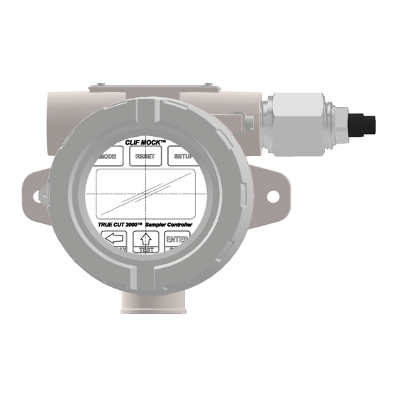
Section 1: Introduction Section 1: Introduction DESCRIPTION The Clif Mock True Cut 2000 Sampler Controller, see Figure 1, is an electronic controller that can be used to control any pneumatic device. When paired with a liquid/gas sample pump, the device is ideal for sampling liquid or gas flow streams. -
Page 8: Section 2: True Cut 2000 Sampler Controller Components And Specifications
True Cut 2000 Sampler Controller Section 2: True Cut 2000 Sampler Controller Components and Specifications DISPLAY Dual readouts in the front panel display provide a real-time sample count during operation and guide users through configurable settings during device setup. In addition, a user can initiate a scrolling display of performance status indicators and total volumes on demand during normal operation. -
Page 9: Specification
Section 2: True Cut 2000 Sampler Controller Components and Specifications Figure 3: Serial Tag SPECIFICATION Table 1: TC2000 Sampler Controller Enclosure Explosion Proof, Type 4 enclosure Keypad 6-Key membrane switch, Password-protected security available Switch Explosion Proof external Momentary Control Switch Power Supply 6-30V DC external power supply True Cut 2000 Sampler Controller: -40°C to 70°C (-40°F to 158°F) - Page 10 True Cut 2000 Sampler Controller Sampling Methods (Time) Batch Sampling (controller calculates the frequency of samples required to fill the bottle in a specified time) Time Sampling (controller collects samples at user-configured frequency until specified number of samples is collected) Continuous Time Sampling (controller collects samples at user- configured frequency until sampling period is manually terminated) Sampling Methods (Volume)
-
Page 11: Section 3: Installation
Section 3: Installation Section 3: Installation GENERAL INFORMATION The True Cut 2000 Sampler Controller is typically installed after the sample probe and flowmeter are installed in a pipeline. For sampling liquid or gas, the controller should be installed with a sample pump, a sample probe, a pressure regulator, a flowmeter, and a receiver. -
Page 12: Class I, Division 2 (Csa) Installations
True Cut 2000 Sampler Controller Caution All signal cable from other devices and power must be installed accordance with local wiring practices for area classification. The cable used between the True Cut 2000 and other devices must be either armored MC-HL type cable or standard cable routed through conduit. If standard cable is used, a conduit seal must be installed within 18 inches from the True Cut 2000. -
Page 13: Grounding Procedures
Section 3: Installation Figure 5: True Cut 2000 circuit board terminal block layout 1. Unscrew the cover of the enclosure counter-clockwise until it separates from the main body of the enclosure. 2. Using a small standard blade screwdriver, remove the two #4-40 x 7/8-in. screws located to the right and left side of the display. -
Page 14: External Dc Power Supply
True Cut 2000 Sampler Controller Figure 6: Internal ground screw location EXTERNAL DC POWER SUPPLY The True Cut 2000 Sampler Controller can be connected to a customer-supplied 6-30V DC power supply by a two-conductor cable. If the controller is installed in a hazardous area, follow the instruction under the Hazardous Area Installations Instruction. -
Page 15: Communications
Section 3: Installation Figure 7: External DC Power wiring diagram COMMUNICATIONS Two RS-485 communication ports (COM1 and COM2) are available for use with any device that is capable of reading Modbus data. Communications connections are not required for basic operation of the controller. Figure 8: RS-485 communications wiring diagram TURBINE INPUT The flowmeter input can be provided by the magnetic pickup of a turbine flowmeter. -
Page 16: Digital Output (Solid State Relay)
True Cut 2000 Sampler Controller Figure 9: Turbine flowmeter input wiring diagram DIGITAL OUTPUT (SOLID STATE RELAY) Digital Output is used to drive the external low power solenoid based on the True Cut 2000 Sampler Controller configuration. The rating of the Digital Output circuit is 30V DC at 60mA max. Figure 10: Digital Output wiring diagram, Solid State Relay with 30V DC @60mA max. -
Page 17: Section 4: Operating The Controller
Section 4: Operating the Controller Section 4: Operating the Controller FRONT PANEL The front panel of the controller contains a Liquid Crystal Display (LCD) with a dual readout and a 6-button keypad for configuring the controller and retrieving data. During operation, the LCD displays the sample count for the current sampling period, as shown in Figure 11. -
Page 18: Common Keypad Functions
True Cut 2000 Sampler Controller • External Reset Control Switch—provides 3 different functions based on the hold time. 0.3 second—scroll through next parameter on display 5.0 seconds—one button quick RESET and START sampling function if the Sampler Controller is in Stop or Idle mode 10 seconds—if the system is running, it will issue a STOP Command;... -
Page 19: Run Time
Section 4: Operating the Controller 0.000 RUN TIME RUN TIME - DAYS BOTTOM 0.00 PERCENT PERCENT DONE DONE BOTTOM 0.00 (GAL) FLOW RATE FLOW RATE (/SEC) BOTTOM 0.000 (GAL) TOTAL VOLUME TOTAL VOLUME BOTTOM 0.00 (GAL) GRAND TOTAL GRAND TOTAL VOLUME BOTTOM 6.656... -
Page 20: Firmware Version
True Cut 2000 Sampler Controller placed in “Stop” mode), status will display as “Stop.” When a sample period has ended, status will display as “Done.” FIRMWARE VERSION It may be helpful to confirm the firmware version if a question arises about the operation of the device. Over time, multiple firmware versions may be released with varying functionality. -
Page 21: Section 5: Programming The Controller
Section 5: Programming the Controller Section 5: Programming the Controller Before programming the controller, review Section 4, to become familiar with the controller keys and their functions. Because the keypad is protected beneath the lid of the instrument, the enclosure must be opened to access the keypad. -
Page 22: Continuous Time Sampling
True Cut 2000 Sampler Controller CONTINUOUS TIME SAMPLING 1. Press SAMPLE SETUP and press UP ARROW/ TEST to select “Cont.” Press ENTER. 2. Enter the “Sample Frequency” in seconds by pressing UP ARROW/ TEST. Values from 1 to 65535 may be entered. -
Page 23: Sampler Test
Section 5: Programming the Controller 10. Press RESET to begin sampling. When the sampling job is completed, the final sample count will be displayed in the top readout and the words “Sampling Done” will appear in the bottom readout. SAMPLER TEST The TEST key on the keypad allows a user to test sampler function by activating the solenoid for a short period. -
Page 24: Advanced Security
1. Press LEFT ARROW, UP ARROW and ENTER all together to enter "Load Default" mode. 2. No further action needed. SECURITY BYPASS Have you misplaced your security password? Sensia gives you the ability to restore access quickly and easily with a one-time bypass code. Note To obtain a bypass code, you must provide Sensia with a number generated using the following procedure. - Page 25 The word “BYPASS” will appear in the bottom display, and a number will appear in the top display. 3. Record this number. 4. Call a Sensia sales representative and provide the number from the display and the serial number of the True Cut 2000 instrument. After verifying your identity, sales representative will provide you with a one- time bypass code.
-
Page 26: Section 6: True Cut 2000 Sampler Controller Spare Parts
Class I, Division 1. Use of spare parts other than those identified by Sensia LLC. voids hazardous area certification. Sensia bears no legal responsibility for the performance of a product that has been serviced or repaired with parts that are not authorized by Sensia. - Page 27 Section 6: True Cut 2000 Sampler Controller Spare Parts Page Left Intentionally Blank...
- Page 28 True Cut 2000 Sampler Controller Page Left Intentionally Blank...
- Page 29 Section 6: True Cut 2000 Sampler Controller Spare Parts Page Left Intentionally Blank...
-
Page 30: Appendix A: Communications Protocol
Appendix A: Communications Protocol Firmware Version: 3.00 Register Table Version: 7 INTRODUCTION The communications protocol for the True Cut 2000 is in accordance with Modicon, Inc. RTU Mode Modbus® as described in Modicon Modbus Protocol Reference Guide, PI-MBUS-300 Rev. J, June 1996. All registers are implemented as 4X or holding registers. - Page 31 Note All registers cited in this document refer to the address of the register that appears in the actual Modbus® message. For example, register 8000 has an address of 0x1F40 hexa- decimal in the message. Communications Configuration Register Register Description Data Access Default...
- Page 32 True Cut 2000 Configuration Register Register Description Data Access Default Min/Max (Decimal) (Hex) Type — 1 (Reserved) 1700 Sampler Function Type 0 – 0 – Batch — 1701 Batch 1 – Time 2 – Volume 3 – Continuous 4 – Test Function Mode 0 –...
- Page 33 Sample Bottle Size 1714 300.00 25 / 10000 Sample Grab Size 1716 0.05 / 10 — K-Factor 1718 900.00 Volume Per Sample 1720 5.00 0.05 / 100 — (Reserved) 1722 — (Reserved) 1724 Holding Registers Register Register Description Data Access (Decimal) (Hex) Type...
-
Page 34: Appendix B: Publisher Notes
Sensia pursues a policy of continuous improvement, and information given herein may be updated without notice. Further, this information is proprietary to Sensia, and must not be disclosed to any third party except as may be required to operate the equipment supplied in accordance with the purposes for which it was sold... -
Page 36: Contact Us
No. 701, S. No. 144&145, Samrat Coraopolis, PA Ashoka Path, YERAWADA, Pune, P.O.BOX 16776, Plot WWA 115, 15108-7766 Maharashtra, India, 411006 DUBAI, U.A.E sensiaglobal.com Add intelligent action to your oil & gas solutions © Sensia LLC 2020. All rights reserved.
Need help?
Do you have a question about the CLIF MOCK TC2000 and is the answer not in the manual?
Questions and answers